
- Каталог оборудования Siemens
- Каталог продуктов Siemens Industry
- Приводная техника
- Преобразователи
- Стандартные преобразователи
- Общая информация о базовых преобразователях SINAMICS V
- Преобразователи частоты общего назначения SINAMICS G
- Высокопроизводительные преобразователи SINAMICS S
- Сервопреобразователь SINAMICS S110
- SINAMICS S120
- Excellence in Motion Control
- Системный обзор
- System data
- Модули контроля
- Сетевые модули и сетевые компоненты питания
- Модули двигателей
- SINAMICS S120 Chassis Format Units
- Air-cooled units
- Power Modules
- Active Line Modules
- Active Interface Modules
- Smart Line Modules
- Basic Line Modules
- Motor Modules
- Mounting device for power blocks
- Liquid-cooled units
- Power Modules
- Active Line Modules
- Active Interface Modules
- Basic Line Modules
- Motor Modules
- System components
- Line filters
- Line reactors
- Recommended line-side system components
- Braking Modules
- Braking Modules
- Braking resistors
- DC link fuses
- Motor reactors
- dv/dt filters plus VPL
- dv/dt filters compact plus VPL
- Sine-wave filters
- Safe Brake Adapter SBA
- Силовые модули
- Дополнительные системные компоненты
- Компоненты
- Кабели и штекеры MOTION-CONNECT
- Инструментальное программное обеспечение
- Safety Integrated
- Конфигурирование
- Сервис и документация
- Услуги и документация
- Приводная система SINAMICS S120
- Сертификация
- SIPLUS SINAMICS S120
- SINAMICS S120M distributed servo drive
- SINAMICS S120 Combi
- SINAMICS S120 Chassis Format Units
- SINAMICS S120 Cabinet Modules
- SINAMICS S150 converter cabinet units
- MICROMASTER
- SIPLUS POSMO A
- SIMODRIVE POSMO
- LOHER DYNAVERT Drive System
- Преобразователи на среднее напряжение
- Преобразователи постоянного тока
- Стандартные преобразователи
- Двигатели переменного тока
- Generators
- Мотор-редукторы
- Flender Gear Units
- Couplings
- Инструментальное программное обеспечение
- Дополнительные компоненты
- Преобразователи
- Техника автоматизации
- Energy
- Автоматизация и безопасность зданий
- Низковольтная коммутационная техника
- Технология безопасности
- Системные решения и продукты для отраслей
- Сервис
- Приводная техника
Braking Modules
- Заказные данные (9)
- Аксессуары (1)
- Информационные материалы
Информационные материалы

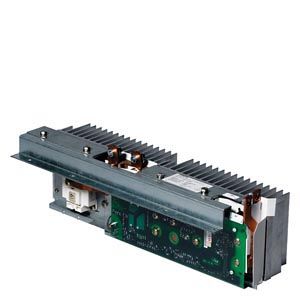
A Braking Module and the matching external braking resistor are required to bring drives to a controlled standstill in the event of a power failure (e.g. with an EMERGENCY STOP) or to limit the DC link voltage for brief periods of regenerative operation, e.g. if the Line Module is not capable of energy recovery.
The Braking Module includes the power electronics and the associated control circuit. During operation, the DC link energy is converted to heat loss in an external braking resistor.
The Braking Module works independently of the converter control.
Several Braking Modules can be operated in parallel, but a separate braking resistor must be connected to each Braking Module.
Braking Modules are designed to be integrated into air-cooled Motor Modules, Line Modules or Power Modules and are cooled by the fans on these modules. The supply voltage for the electronics is taken from the DC link. The Braking Modules are connected to the DC link by means of the busbar sets included in the scope of supply or flexible cables and, in the case of Basic Line Modules of frame size GB or GD, using a separate cable harness set.
The activation threshold of the Braking Module can be adjusted by means of a DIP switch. The braking power values specified in the technical specifications apply to the upper activation threshold.
Дизайн
The Braking Modules have the following interfaces as standard:
- 1 DC link connection
- 1 braking resistor connection
- 1 digital input (block Braking Module / acknowledge error)
- 1 digital output (Braking Module inhibited)
- 1 DIP switch for adjusting the activation threshold
Information about Braking Module activation thresholds and other notes are included in the SINAMICS Low Voltage Engineering Manual.
Характеристика

Load diagram for Braking Modules and braking resistor
Интеграция

Connection example of a Braking Module
Технические данные
Line voltage 380 ... 480 V 3 AC
DC link voltage 510 ... 720 V DCBraking Module
6SL3300-1AE31-3AA0
6SL3300-1AE32-5AA0
6SL3300-1AE32-5BA0
Power
- Rated power PDB
kW
25
50
50
- Peak power P15
kW
125
250
250
- Power P20
kW
100
200
200
- Power P40
kW
50
100
100
Activation thresholds
(adjustable via DIP switch)
V
774 (factory setting)
or 673774 (factory setting)
or 673774 (factory setting)
or 673Digital inputs
in accordance with IEC 61131‑2 Type 1
- Voltage
V
24 DC
24 DC
24 DC
- Low level (an open digital input is interpreted as "low")
V
-3 ... +5
-3 ... +5
-3 ... +5
- High level
V
15 ... 30
15 ... 30
15 ... 30
- Current consumption at 24 V DC, typ.
mA
10
10
10
- Conductor cross-section, max.
mm2
1.5
1.5
1.5
Digital outputs
sustained-short-circuit-proof
- Voltage
V
24 DC
24 DC
24 DC
- Load current per digital output, max.
mA
500
500
500
- Conductor cross-section, max.
mm2
1.5
1.5
1.5
R1/R2 connection
M8 nut
M8 nut
M8 nut
- Conductor cross-section, max.
mm2
35
50
50
Weight, approx.
kg (lb)
3.6 (7.9)
7.3 (16.1)
7.5 (16.5)
Suitable for installation in air-cooled Power Modules, Line Modules or Motor Modules
- Air-cooled
Frame size
FX/FB
GX/GB/GD 1)
HX/JX
1) Cable harness set 6SL3366-2NG00-0AA0 is required to connect the Braking Module to a Basic Line Module of frame size GB or GD.
Line voltage 500 ... 600 V 3 AC
DC link voltage 675 ... 900 V DCBraking Module
6SL3300-1AF31‑3AA0
6SL3300-1AF32‑5AA0
6SL3300-1AF32‑5BA0
Power
- Rated power PDB
kW
25
50
50
- Peak power P15
kW
125
250
250
- Power P20
kW
100
200
200
- Power P40
kW
50
100
100
Activation thresholds
(adjustable via DIP switch)
V
967 (factory setting)
or 841967 (factory setting)
or 841967 (factory setting)
or 841Digital inputs
in accordance with IEC 61131‑2 Type 1
- Voltage
V
24 DC
24 DC
24 DC
- Low level (an open digital input is interpreted as "low")
V
-3 ... +5
-3 ... +5
-3 ... +5
- High level
V
15 ... 30
15 ... 30
15 ... 30
- Current consumption at 24 V DC, typ.
mA
10
10
10
- Conductor cross-section, max.
mm2
1.5
1.5
1.5
Digital outputs
sustained-short-circuit-proof
- Voltage
V
24 DC
24 DC
24 DC
- Load current per digital output, max.
mA
500
500
500
- Conductor cross-section, max.
mm2
1.5
1.5
1.5
R1/R2 connection
M8 nut
M8 nut
M8 nut
- Conductor cross-section, max.
mm2
35
50
50
Weight, approx.
kg (lb)
3.6 (7.9)
7.3 (16.1)
7.5 (16.5)
Suitable for installation in air-cooled Power Modules, Line Modules or Motor Modules
- Air-cooled
Frame size
FX/FB
GX/GB/GD 1)
HX/JX
1) Cable harness set 6SL3366-2NG00-0AA0 is required to connect the Braking Module to a Basic Line Module of frame size GB or GD.
Line voltage 660 ... 690 V 3 AC
DC link voltage 890 ... 1035 V DCBraking Module
6SL3300-1AH31-3AA0
6SL3300-1AH32-5AA0
6SL3300-1AH32-5BA0
Power
- Rated power PDB
kW
25
50
50
- Peak power P15
kW
125
250
250
- Power P20
kW
100
200
200
- Power P40
kW
50
100
100
Activation thresholds
(adjustable via DIP switch)
V
1158 (factory setting)
or 10701158 (factory setting)
or 10701158 (factory setting)
or 1070Digital inputs
in accordance with IEC 61131‑2 Type 1
- Voltage
V
24 DC
24 DC
24 DC
- Low level (an open digital input is interpreted as "low")
V
-3 ... +5
-3 ... +5
-3 ... +5
- High level
V
15 ... 30
15 ... 30
15 ... 30
- Current consumption at 24 V DC, typ.
mA
10
10
10
- Conductor cross-section, max.
mm2
1.5
1.5
1.5
Digital outputs
sustained-short-circuit-proof
- Voltage
V
24 DC
24 DC
24 DC
- Load current per digital output, max.
mA
500
500
500
- Conductor cross-section, max.
mm2
1.5
1.5
1.5
R1/R2 connection
M8 nut
M8 nut
M8 nut
- Conductor cross-section, max.
mm2
35
50
50
Weight, approx.
kg (lb)
3.6 (7.9)
7.3 (16.1)
7.5 (16.5)
Suitable for installation in air-cooled Power Modules, Line Modules or Motor Modules
- Air-cooled
Frame size
FX/FB
GX/GB/GD 1)
HX/JX
1) Cable harness set 6SL3366-2NG00-0AA0 is required to connect the Braking Module to a Basic Line Module of frame size GB or GD.