
- Каталог оборудования Siemens
- Каталог продуктов Siemens Industry
- Приводная техника
- Преобразователи
- Стандартные преобразователи
- Общая информация о базовых преобразователях SINAMICS V
- Преобразователи частоты общего назначения SINAMICS G
- Высокопроизводительные преобразователи SINAMICS S
- Сервопреобразователь SINAMICS S110
- SINAMICS S120
- Excellence in Motion Control
- Системный обзор
- System data
- Модули контроля
- Сетевые модули и сетевые компоненты питания
- Модули двигателей
- SINAMICS S120 Chassis Format Units
- Air-cooled units
- Power Modules
- Active Line Modules
- Active Interface Modules
- Smart Line Modules
- Basic Line Modules
- Motor Modules
- Mounting device for power blocks
- Liquid-cooled units
- Power Modules
- Power Modules
- Active Line Modules
- Active Interface Modules
- Basic Line Modules
- Motor Modules
- System components
- Line filters
- Line reactors
- Recommended line-side system components
- Braking Modules
- Braking resistors
- DC link fuses
- Motor reactors
- dv/dt filters plus VPL
- dv/dt filters compact plus VPL
- Sine-wave filters
- Safe Brake Adapter SBA
- Силовые модули
- Дополнительные системные компоненты
- Компоненты
- Кабели и штекеры MOTION-CONNECT
- Инструментальное программное обеспечение
- Safety Integrated
- Конфигурирование
- Сервис и документация
- Услуги и документация
- Приводная система SINAMICS S120
- Сертификация
- SIPLUS SINAMICS S120
- SINAMICS S120M distributed servo drive
- SINAMICS S120 Combi
- SINAMICS S120 Chassis Format Units
- SINAMICS S120 Cabinet Modules
- SINAMICS S150 converter cabinet units
- MICROMASTER
- SIPLUS POSMO A
- SIMODRIVE POSMO
- LOHER DYNAVERT Drive System
- Преобразователи на среднее напряжение
- Преобразователи постоянного тока
- Стандартные преобразователи
- Двигатели переменного тока
- Generators
- Мотор-редукторы
- Flender Gear Units
- Couplings
- Инструментальное программное обеспечение
- Дополнительные компоненты
- Преобразователи
- Техника автоматизации
- Energy
- Автоматизация и безопасность зданий
- Низковольтная коммутационная техника
- Технология безопасности
- Системные решения и продукты для отраслей
- Сервис
- Приводная техника
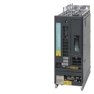
Power Modules
- Заказные данные (4)
- Аксессуары (1)
- Информационные материалы
Информационные материалы
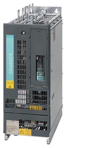
The Power Module comprises a line rectifier, a DC link and an inverter to supply the motor.
Power Modules are designed for drives that are not capable of regenerating energy to the mains supply. If the motor produces energy during braking, a Braking Module with braking resistors will be required.
Liquid-cooled Power Modules are especially suitable for applications where installation space is restricted and environmental conditions are harsh. Liquid cooling ensures efficient heat dissipation.
Power Modules in the chassis format can be connected to grounded TN/TT systems and non-grounded IT systems.
Дизайн
The liquid-cooled Power Modules have the following interfaces as standard:
- 1 line supply connection
- 1 motor connection
- 1 connection for the 24 V DC electronics power supply
- 1 DC link connection
- 3 DRIVE‑CLiQ sockets
- 1 temperature sensor input for KTY84‑130, Pt1000, PTC or Pt100 (Pt1000 can be used from firmware V4.7 HF17)
- 1 connection for Safe Brake Adapter
- 1 connection for Safety Integrated
- 2 PE connections
- 2 coolant connections
The CU310-2 Control Unit can be integrated into the liquid-cooled Power Modules.
The status of the Power Modules is indicated via three LEDs.
The scope of supply of the Power Modules includes:
- 1 DRIVE‑CLiQ cable for connection to the Control Unit
- 2 seals for coolant connections
- 1 set of warning labels in 30 languages
(BG, CN, CZ, DE, DK, EE, ES, FI, FR, GB, GR, HU, IE, IS, IT, JP, KR, LT, LV, MT, NL, NO, PL, PT, RO, RU, SE, SI, SK, TR)
Интеграция
The Power Modules communicate with the higher-level control module via DRIVE‑CLiQ. The Control Unit in this case could be a CU310-2, CU320-2 or a SIMOTION D Control Unit. An external 24 V DC power supply is required to operate liquid-cooled Power Modules.
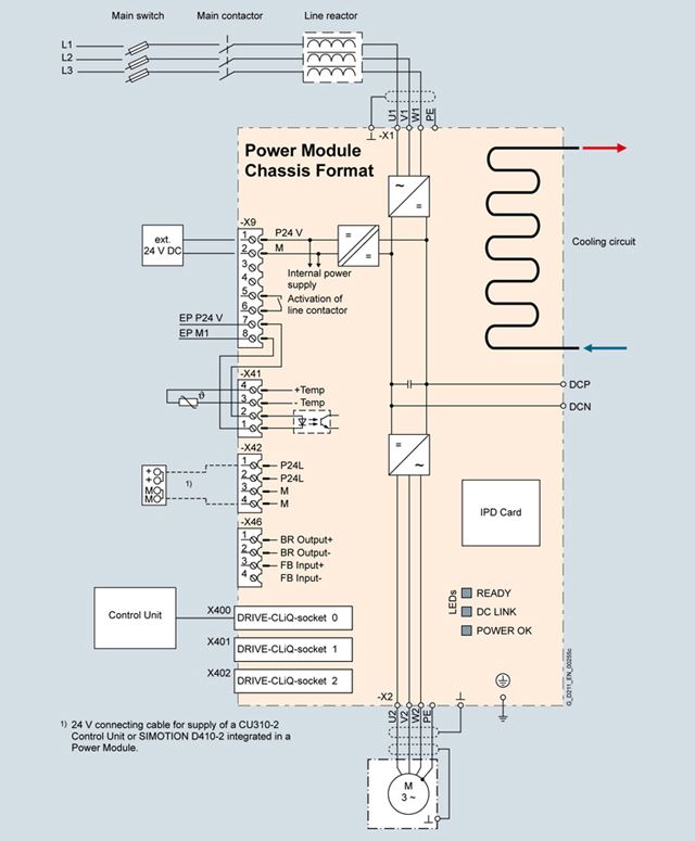
Connection example of a liquid-cooled Power Module in the chassis format
Note:
The integrated 24 V power supply at connector X42 can have a maximum load of 2 A. When the Control Unit is supplied from the integrated power supply, the total load of the digital outputs must be carefully observed to ensure that the 2 A is not exceeded.
Технические данные
General technical specifications
Electrical specifications
Line connection voltage
Up to 2000 m (6562 ft) above sea level
380 … 480 V 3 AC ±10 % (-15 % < 1 min)
Line power factor
for a 3 AC line supply voltage and rated output
- Basic fundamental (cos φ1)
>0.96
- Total (λ)
0.75 ... 0.93
Efficiency
> 98 %
DC link voltage, approx.
1.35 × line voltage
Output voltage, approx.
0 ... 0.97 × Uline
Output frequency 1)
- Control mode Servo
0 ... 550 Hz
- Control mode Vector
0 ... 550 Hz
- Control mode V/f
0 ... 550 Hz
Electronics power supply
24 V DC -15 %/+20 %
Main contactor control
- Terminal block -X9/5-6
240 V AC, max. 8 A
30 V DC, max. 1 ASafety Integrated
Safety Integrity Level 2 (SIL2) acc. to IEC 61508, Performance Level d (PLd) acc. to EN ISO 13849‑1 and Control Category 3 acc. to EN ISO 13849‑1.
1) Please note:
• The correlation between the maximum output frequency, pulse frequency and current derating. Higher output frequencies on request For further information see https://support.industry.siemens.com/cs/document/104020669
• The correlation between the minimum output frequency and permissible output current (current derating). Information is provided in the SINAMICS Low Voltage Engineering Manual.
Line voltage 380 V ... 480 V 3 AC
Power Modules
6SL3315-1TE32-1AA3
6SL3315-1TE32-6AA3
6SL3315-1TE33-1AA3
6SL3315-1TE35-0AA3
Type rating
- At IL (50 Hz 400 V) 1)
kW
110
132
160
250
- At IH (50 Hz 400 V) 1)
kW
90
110
132
200
- At IL (60 Hz 460 V) 2)
hp
150
200
250
400
- At IH (60 Hz 460 V) 2)
hp
150
200
200
350
Output current
- Rated current Irated O
A
210
260
310
490
- Base-load current IL3)
A
205
250
302
477
- Base-load current IH4)
A
178
233
277
438
- Max. output current Imax O
A
307
375
453
715
Input current
- Rated current Irated I
A
230
285
340
540
- Maximum current Imax I
A
336
411
496
788
Current demand
- 24 V DC auxiliary power supply
A
1.4
1.4
1.5
1.5
Pulse frequency 5)
- Rated frequency
kHz
2
2
2
2
- Pulse frequency, max.
- Without current derating
kHz
2
2
2
2
- With current derating
kHz
8
8
8
8
Power loss, at 50 Hz 400 V 6)
- Dissipated to coolant
kW
2.36
2.97
3.31
5.29
- Dissipated to ambient air
kW
0.06
0.07
0.09
0.14
- Total
kW
2.42
3.04
3.4
5.43
Coolant volume flow 7)
l/min
9
9
12
12
Liquid volume
of the integrated heat exchanger
dm3
0.52
0.52
0.88
0.88
Pressure drop, typ. 8)
for volume flow
Pa
70000
70000
70000
70000
Heat exchanger material
Stainless steel
Stainless steel
Stainless steel
Stainless steel
Sound pressure level LpA
(1 m) at 50/60 Hz
dB
52
52
52
52
Line connection
U1, V1, W1
Hole for M12
Hole for M12
Hole for M12
Hole for M12
- Conductor cross section, max. (IEC)
mm2
2 × 95
2 × 95
2 × 240
2 × 240
DC link connection
DCP, DCN
Hole for M12
Hole for M12
Hole for M12
Hole for M12
- Conductor cross section, max. (IEC)
mm2
2 × 95
2 × 95
2 × 240
2 × 240
Motor connection
U2/T1, V2/T2, W2/T3
Hole for M12
Hole for M12
2 × hole for M12
2 × hole for M12
- Conductor cross section, max. (IEC)
mm2
2 × 95
2 × 95
2 × 240
2 × 240
Cable length, max. 9)
- Shielded
m (ft)
300 (984)
300 (984)
300 (984)
300 (984)
- Unshielded
m (ft)
450 (1476)
450 (1476)
450 (1476)
450 (1476)
PE/GND connection
2 × hole for M12
2 × hole for M12
2 × hole for M12
2 × hole for M12
- Conductor cross section, max. (IEC)
mm2
2 × 95
2 × 95
2 × 240
2 × 240
Dimensions
- Width
mm (in)
265 (10.4)
265 (10.4)
265 (10.4)
265 (10.4)
- Height
mm (in)
836 (32.9)
836 (32.9)
983 (38.7)
983 (38.7)
- Depth
mm (in)
549 (21.6)
549 (21.6)
549 (21.6)
549 (21.6)
Weight, approx.
kg (lb)
77 (170)
77 (170)
108 (238)
108 (238)
Frame size
FL
FL
GL
GL
Minimum short-circuit current 10)
A
3000
3600
4400
8000
1) Rated output of a typical 6-pole standard induction motor based on IL or IH for 3 AC 50 Hz 400 V.
2) Rated output of a typical 6-pole standard induction motor based on IL or IH for 3 AC 60 Hz 460 V.
3) The base-load current IL is based on a duty cycle of 110 % for 60 s or 150 % for 10 s with a duty cycle duration of 300 s.
4) The base-load current IH is based on a duty cycle of 150 % for 60 s or 160 % for 10 s with a duty cycle duration of 300 s.
5)Information regarding the correlation between the pulse frequency and maximum output current/output frequency is provided in the SINAMICS Low Voltage Engineering Manual.
6) The specified power loss represents the maximum value at 100 % utilization. The value is lower under normal operating conditions. To ensure safe dissipation of the minor power loss released to the ambient air, it is important to follow the instructions pertaining to control cabinet installation in the SINAMICS Low Voltage Engineering Manual.
7) The value applies to coolants comprising water and a mixture of water and anti-freeze agent.
8) The value is valid for water as coolant. Additional information and notes on other coolants is provided in the SINAMICS Low Voltage Engineering Manual.
9) Longer cable lengths for specific configurations are available on request. For additional information, please refer to the SINAMICS Low Voltage Engineering Manual.
10) Current required for reliably triggering protective devices.