
- Каталог оборудования Siemens
- Каталог продуктов Siemens Industry
- Приводная техника
- Преобразователи
- Стандартные преобразователи
- Общая информация о базовых преобразователях SINAMICS V
- Преобразователи частоты общего назначения SINAMICS G
- Высокопроизводительные преобразователи SINAMICS S
- Сервопреобразователь SINAMICS S110
- SINAMICS S120
- Excellence in Motion Control
- Системный обзор
- System data
- Модули контроля
- Сетевые модули и сетевые компоненты питания
- Модули двигателей
- SINAMICS S120 Chassis Format Units
- Air-cooled units
- Power Modules
- Active Line Modules
- Active Interface Modules
- Smart Line Modules
- Basic Line Modules
- Motor Modules
- Mounting device for power blocks
- Liquid-cooled units
- Power Modules
- Active Line Modules
- Active Interface Modules
- Basic Line Modules
- Basic Line Modules
- Motor Modules
- System components
- Line filters
- Line reactors
- Recommended line-side system components
- Braking Modules
- Braking resistors
- DC link fuses
- Motor reactors
- dv/dt filters plus VPL
- dv/dt filters compact plus VPL
- Sine-wave filters
- Safe Brake Adapter SBA
- Силовые модули
- Дополнительные системные компоненты
- Компоненты
- Кабели и штекеры MOTION-CONNECT
- Инструментальное программное обеспечение
- Safety Integrated
- Конфигурирование
- Сервис и документация
- Услуги и документация
- Приводная система SINAMICS S120
- Сертификация
- SIPLUS SINAMICS S120
- SINAMICS S120M distributed servo drive
- SINAMICS S120 Combi
- SINAMICS S120 Chassis Format Units
- SINAMICS S120 Cabinet Modules
- SINAMICS S150 converter cabinet units
- MICROMASTER
- SIPLUS POSMO A
- SIMODRIVE POSMO
- LOHER DYNAVERT Drive System
- Преобразователи на среднее напряжение
- Преобразователи постоянного тока
- Стандартные преобразователи
- Двигатели переменного тока
- Generators
- Мотор-редукторы
- Flender Gear Units
- Couplings
- Инструментальное программное обеспечение
- Дополнительные компоненты
- Преобразователи
- Техника автоматизации
- Energy
- Автоматизация и безопасность зданий
- Низковольтная коммутационная техника
- Технология безопасности
- Системные решения и продукты для отраслей
- Сервис
- Приводная техника

Basic Line Modules
- Заказные данные (7)
- Аксессуары (1)
- Информационные материалы
Информационные материалы
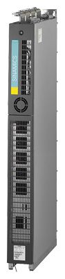
Basic Line Modules are used for applications where energy is not fed back into the line supply or where energy is exchanged in the DC link between axes operating in the motor and generator modes. The connected Motor Modules are pre-charged via the thyristor gate control. Basic Line Modules are designed for connection to grounded TN/TT and non-grounded IT supply systems.
Liquid-cooled Basic Line Modules are especially suitable for applications where installation space is restricted and environmental conditions are harsh. Liquid cooling ensures efficient heat dissipation.
Дизайн
The liquid-cooled Basic Line Modules have the following interfaces as standard:
- 1 line supply connection
- 1 connection for the 24 V DC electronics power supply
- 1 DC link connection (DCP, DCN) for supplying the connected Motor Modules
- 3 DRIVE‑CLiQ sockets
- 1 temperature sensor input for KTY84‑130, Pt1000, PTC or Pt100 (Pt1000 can be used from firmware V4.7 HF17)
- 1 PE connection
- 2 coolant connections
The status of the Basic Line Modules is indicated via three LEDs.
The scope of supply of the Power Modules includes:
- 1 DRIVE‑CLiQ cable for connection to the Control Unit
- 2 seals for coolant connections
- 1 set of warning labels in 30 languages
(BG, CN, CZ, DE, DK, EE, ES, FI, FR, GB, GR, HU, IE, IS, IT, JP, KR, LT, LV, MT, NL, NO, PL, PT, RO, RU, SE, SI, SK, TR)
Интеграция
The liquid-cooled Basic Line Modules communicate with the higher-level control module via DRIVE‑CLiQ. The control module in this case can be a CU320-2 or a SIMOTION D Control Unit. An external 24 V DC power supply is required to operate liquid-cooled Basic Line Modules.

Connection example of a Basic Line Module
Технические данные
General technical specifications
Electrical specifications
Line power factor at rated power
- Basic fundamental (cos φ1)
>0.96
- Total (λ)
0.75 ... 0.93
Efficiency
>99 %
DC link voltage, approx. 1)
1.35 × line voltage
Main contactor control
- Terminal block -X9/5-6
240 V AC, max. 8 A
30 V DC, max. 1 A1) The DC link voltage is unregulated and load-dependent. For additional information, please refer to the SINAMICS Low Voltage Engineering Manual.
Line voltage 380 ... 480 V 3 AC
Basic Line Modules
6SL3335-1TE37-4AA3
6SL3335-1TE41-2AA3
6SL3335-1TE41-7AA3
Rated power
- At Irated DC (50 Hz 400 V)
kW
360
600
830
- At IH (50 Hz 400 V)
kW
280
450
650
- At Irated DC (60 Hz 460 V)
hp
555
925
1280
- At IH (60 Hz 460 V)
hp
430
690
1000
DC link current
- Rated current Irated DC
A
740
1220
1730
- Base-load current IH DC 1)
A
578
936
1350
- Maximum current Imax DC
A
1110
1830
2595
Input current
- Rated current Irated I
A
610
1000
1420
- Maximum current Imax I
A
915
1500
2130
Current demand
- 24 V DC auxiliary power supply
A
0.7
0.7
0.7
DC link capacitance
- Basic Line Module
μF
12000
20300
26100
- Drive line-up, max.
μF
96000
162400
208800
Power loss, at
50 Hz 400 V 2)- Dissipated to coolant
kW
2.7
4.36
5.82
- Dissipated to ambient air
kW
0.25
0.41
0.57
- Total
kW
2.95
4.77
6.39
Coolant volume flow 3)
l/min
9
9
12
Liquid volume
of the integrated heat exchanger
dm3
0.45
0.45
0.79
Pressure drop, typ. 4)
for volume flow
Pa
70000
70000
70000
Heat exchanger material
Aluminum
Aluminum
Aluminum
Sound pressure level LpA
(1 m) at 50/60 Hz
dB
54
56
56
Line connection
U1, V1, W1
2 × M12 nut
2 × M12 nut
2 × M12 nut
- Conductor cross section, max. (IEC)
mm2
4 × 240
4 × 240
4 × 240
DC link connection
DCP, DCN
2 × M12 nut
Busbar
2 × M12 nut
Busbar
2 × M12 nut
Busbar
PE/GND connection
2 × M12 nut
2 × M12 nut
2 × M12 nut
- Conductor cross section, max. (IEC)
mm2
4 × 240
4 × 240
4 × 240
Cable length, max. 5)
- Shielded
m (ft)
2600 (8531)
4000 (13124)
4800 (15749)
- Unshielded
m (ft)
3900 (12796)
6000 (19686)
7200 (23623)
Dimensions
- Width
mm (in)
160 (6.3)
160 (6.3)
160 (6.3)
- Height
mm (in)
1137 (44.8)
1137 (44.8)
1562 (61.5)
- Depth
mm (in)
545 (21.5)
545 (21.5)
545 (21.5)
Weight, approx.
kg (lb)
108 (238)
108 (238)
185 (408)
Frame size
FBL
FBL
GBL
Minimum short-circuit current 6)
A
8800
12400
20000
1) The base-load current IH DC is the basis for a duty cycle of 150 % for 60 s or Imax DC for 5 s with a duty cycle duration of 300 s.
2) The specified power loss represents the maximum value at 100% utilization. The value is lower under normal operating conditions. To ensure safe dissipation of the minor power loss released to the ambient air, it is important to follow the instructions pertaining to control cabinet installation in the SINAMICS Low Voltage Engineering Manual.
3) The value applies to coolants comprising water and a mixture of water and anti-freeze agent.
4) The value is valid for water as coolant. Additional information and notes on other coolants is provided in the SINAMICS Low Voltage Engineering Manual.
5) Total of all motor cables and DC link. Longer cable lengths for specific configurations are available on request. For additional information, please refer to the SINAMICS Low Voltage Engineering Manual.
6) Current required for reliably triggering protective devices.
Line voltage 500 ... 690 V 3 AC
Basic Line Modules
6SL3335-1TG34-2AA3
6SL3335-1TG37-3AA3
6SL3335-1TG41-3AA3
6SL3335-1TG41-7AA3
Rated power
- At Irated DC (50 Hz 690 V)
kW
355
630
1100
1370
- At IH (50 Hz 690 V)
kW
275
475
840
1070
- At Irated DC (50 Hz 500 V)
kW
245
420
750
950
- At IH (50 Hz 500 V)
kW
200
345
610
775
- At Irated DC (60 Hz 575 V)
hp
395
705
1230
1530
- At IH (60 Hz 575 V)
hp
305
530
940
1195
DC link current
- Rated current Irated DC
A
420
730
1300
1650
- Base-load current IH DC 1)
A
328
570
1014
1287
- Maximum current Imax DC
A
630
1095
1950
2475
Input current
- Rated current Irated I
A
340
600
1070
1350
- Maximum current Imax I
A
510
900
1605
2025
Current demand
- 24 V DC auxiliary power supply
A
0.7
0.7
0.7
0.7
DC link capacitance
- Basic Line Module
μF
4800
7700
15500
19300
- Drive line-up, max.
μF
38400
61600
124000
154400
Power loss, at 50 Hz 690 V 2)
- Dissipated to coolant
kW
1.55
2.71
4.66
5.7
- Dissipated to ambient air
kW
0.21
0.38
0.43
0.55
- Total
kW
1.76
3.09
5.09
6.25
Coolant volume flow 3)
l/min
9
9
12
12
Liquid volume
of the integrated heat exchanger
dm3
0.45
0.45
0.79
0.79
Pressure drop, typ. 4)
for volume flow
Pa
70000
70000
70000
70000
Heat exchanger material
Aluminum
Aluminum
Aluminum
Aluminum
Sound pressure level LpA
(1 m) at 50/60 Hz
dB
54
54
56
56
Line connection
U1, V1, W1
2 × M12 nut
2 × M12 nut
2 × M12 nut
2 × M12 nut
- Conductor cross section, max. (IEC)
mm2
4 × 240
4 × 240
4 × 240
4 × 240
DC link connection
DCP, DCN
2 × M12 nut
Busbar
2 × M12 nut
Busbar
2 × M12 nut
Busbar
2 × M12 nut
Busbar
PE/GND connection
2 × M12 nut
2 × M12 nut
2 × M12 nut
2 × M12 nut
- Conductor cross section, max. (IEC)
4 × 240
4 × 240
4 × 240
4 × 240
Cable length, max. 5)
- Shielded
m (ft)
1500 (4921)
1500 (4921)
2250 (7382)
2250 (7382)
- Unshielded
m (ft)
2250 (7382)
2250 (7382)
3375 (11073)
3375 (11073)
Dimensions
- Width
mm (in)
160 (6.3)
160 (6.3)
160 (6.3)
160 (6.3)
- Height
mm (in)
1137 (44.8)
1137 (44.8)
1562 (61.5)
1562 (61.5)
- Depth
mm (in)
545 (21.5)
545 (21.5)
545 (21.5)
545 (21.5)
Weight, approx.
kg (lb)
108 (238)
108 (238)
185 (408)
185 (408)
Frame size
FBL
FBL
GBL
GBL
Minimum short-circuit current 6)
A
4400
7200
16800
18900
1) The base-load current IH DC is the basis for a duty cycle of 150 % for 60 s or Imax DC for 5 s with a duty cycle duration of 300 s.
2) The specified power loss represents the maximum value at 100% utilization. The value is lower under normal operating conditions. To ensure safe dissipation of the minor power loss released to the ambient air, it is important to follow the instructions pertaining to control cabinet installation in the SINAMICS Low Voltage Engineering Manual.
3) The value applies to coolants comprising water and a mixture of water and anti-freeze agent.
4) The value is valid for water as coolant. Additional information and notes on other coolants is provided in the SINAMICS Low Voltage Engineering Manual.
5) Total of all motor cables and DC link. Longer cable lengths for specific configurations are available on request. For additional information, please refer to the SINAMICS Low Voltage Engineering Manual.
6) Current required for reliably triggering protective devices.