
- Каталог оборудования Siemens
- Каталог продуктов Siemens Industry
- Приводная техника
- Преобразователи
- Стандартные преобразователи
- Общая информация о базовых преобразователях SINAMICS V
- Преобразователи частоты общего назначения SINAMICS G
- Высокопроизводительные преобразователи SINAMICS S
- Сервопреобразователь SINAMICS S110
- SINAMICS S120
- Excellence in Motion Control
- Системный обзор
- System data
- Модули контроля
- Сетевые модули и сетевые компоненты питания
- Модули двигателей
- SINAMICS S120 Chassis Format Units
- Air-cooled units
- Power Modules
- Active Line Modules
- Active Interface Modules
- Smart Line Modules
- Basic Line Modules
- Motor Modules
- Motor Modules
- Mounting device for power blocks
- Liquid-cooled units
- Power Modules
- Active Line Modules
- Active Interface Modules
- Basic Line Modules
- Motor Modules
- System components
- Line filters
- Line reactors
- Recommended line-side system components
- Braking Modules
- Braking resistors
- DC link fuses
- Motor reactors
- dv/dt filters plus VPL
- dv/dt filters compact plus VPL
- Sine-wave filters
- Safe Brake Adapter SBA
- Силовые модули
- Дополнительные системные компоненты
- Компоненты
- Кабели и штекеры MOTION-CONNECT
- Инструментальное программное обеспечение
- Safety Integrated
- Конфигурирование
- Сервис и документация
- Услуги и документация
- Приводная система SINAMICS S120
- Сертификация
- SIPLUS SINAMICS S120
- SINAMICS S120M distributed servo drive
- SINAMICS S120 Combi
- SINAMICS S120 Chassis Format Units
- SINAMICS S120 Cabinet Modules
- SINAMICS S150 converter cabinet units
- MICROMASTER
- SIPLUS POSMO A
- SIMODRIVE POSMO
- LOHER DYNAVERT Drive System
- Преобразователи на среднее напряжение
- Преобразователи постоянного тока
- Стандартные преобразователи
- Двигатели переменного тока
- Generators
- Мотор-редукторы
- Flender Gear Units
- Couplings
- Инструментальное программное обеспечение
- Дополнительные компоненты
- Преобразователи
- Техника автоматизации
- Energy
- Автоматизация и безопасность зданий
- Низковольтная коммутационная техника
- Технология безопасности
- Системные решения и продукты для отраслей
- Сервис
- Приводная техника

Motor Modules
- Заказные данные (27)
- Аксессуары (1)
- Информационные материалы
Информационные материалы

A Motor Module comprises a self-commutated inverter with IGBTs. It generates a variable voltage with variable frequency from the DC link voltage that feeds the connected motor.
Multiple Motor Modules can be operated on a single DC link. This permits energy to be transferred between the Motor Modules. This means that if one Motor Module operating in generator mode produces energy, the energy can be used by another Motor Module operating in motor mode.
Motor Modules are controlled by a Control Unit.
Дизайн
The Motor Modules in the chassis format have the following interfaces as standard:
- 1 motor connection
- 1 connection for the 24 V DC electronics power supply
- 1 DC link connection (DCP, DCN) for connecting to the supply DC link
- 1 DC link connection (DCPA, DCNA) for connecting a Braking Module
- 1 DC link connection (DCPS, DCNS) for connecting a dv/dt filter
- 3 DRIVE‑CLiQ sockets
- 1 temperature sensor input for KTY84‑130, Pt1000, PTC or Pt100 (Pt1000 can be used from firmware V4.7 HF17)
- 1 connection for Safe Brake Adapter
- 1 connection for Safety Integrated
- 2 PE connections
The status of the Motor Modules is indicated via three LEDs.
The scope of supply of the Motor Modules includes:
- DRIVE‑CLiQ cable for connection to the Control Unit
- DRIVE‑CLiQ cable for connection to the next Motor Module
- 1 set of warning labels in 30 languages
(BG, CN, CZ, DE, DK, EE, ES, FI, FR, GB, GR, HU, IE, IS, IT, JP, KR, LT, LV, MT, NL, NO, PL, PT, RO, RU, SE, SI, SK, TR)
Интеграция
The Motor Modules communicate with the higher-level control module via DRIVE-CLiQ. The control module in this case can be a CU320-2 or a SIMOTION D Control Unit.
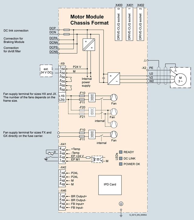
Connection example of a Motor Module
Технические данные
General technical specifications
Electrical specifications
Efficiency
>98.5 %
DC link voltage
(up to 2000 m (6562 ft) above sea level)
510 ... 720 V DC (line supply voltage 380 ... 480 V 3 AC) or
675 ... 1035 V DC (line supply voltage 500 ... 690 V 3 AC)Output frequency 1)
- Control mode Servo
0 ... 550 Hz
- Control mode Vector
0 ... 550 Hz
- Control mode V/f
0 ... 550 Hz
Safety Integrated
Safety Integrity Level 2 (SIL2) acc. to IEC 61508, Performance Level d (PLd) acc. to EN ISO 13849-1 and Control Category 3 acc. to EN ISO 13849‑1
1) Please note:
• The correlation between the maximum output frequency, pulse frequency and current derating. Higher output frequencies on request For further information, see https://support.industry.siemens.com/cs/document/104020669
• The correlation between the minimum output frequency and permissible output current (current derating). Information is provided in the SINAMICS Low Voltage Engineering Manual.
Line voltage 380 ... 480 V 3 AC
DC link voltage 510 ... 720 V DCMotor Modules
6SL3320-1TE32-1AA3
6SL3320-1TE32-6AA3
6SL3320-1TE33-1AA3
6SL3320-1TE33-8AA3
6SL3320-1TE35-0AA3
Type rating
- At IL (50 Hz 400 V) 1)
kW
110
132
160
200
250
- At IH (50 Hz 400 V) 1)
kW
90
110
132
160
200
- At IL (60 Hz 460 V) 2)
hp
150
200
250
300
400
- At IH (60 Hz 460 V) 2)
hp
150
200
200
250
350
Output current
- Rated current Irated O
A
210
260
310
380
490
- Base-load current IL3)
A
205
250
302
370
477
- Base-load current IH4)
A
178
233
277
340
438
- Maximum current Imax A
A
307
375
453
555
715
DC link current
- Rated current Irated DC
when supplied via
- Basic/Smart Line Module
A
252
312
372
456
588
- Active Line Module
A
227
281
335
411
529
- Base-load current IL DC 3)
when supplied via
- Basic/Smart Line Module
A
245
304
362
444
573
- Active Line Module
A
221
273
326
400
515
- Base-load current IH DC 4)
when supplied via
- Basic/Smart Line Module
A
224
277
331
405
523
- Active Line Module
A
202
250
298
365
470
Current demand
- 24 V DC auxiliary power supply
A
0.8
0.8
0.9
0.9
0.9
- 400 V AC
A
0.63
1.13
1.8
1.8
1.8
DC link capacitance
μF
4200
5200
6300
7800
9600
Pulse frequency 5)
- Rated frequency
kHz
2
2
2
2
2
- Pulse frequency, max.
- Without current derating
kHz
2
2
2
2
2
- With current derating
kHz
8
8
8
8
8
Power loss, max. 6)
- At 50 Hz 400 V
kW
1.86
2.5
2.96
3.67
4.28
- At 60 Hz 460 V
kW
1.94
2.6
3.1
3.8
4.5
Cooling air requirement
m3/s (ft3/s)
0.17 (6.00)
0.23 (8.12)
0.36 (12.7)
0.36 (12.7)
0.36 (12.7)
Sound pressure level LpA
(1 m) at 50/60 Hz
dB
64/67
71/71
69/73
69/73
69/73
DC link connection
DCP, DCN
M10 screw
M10 screw
M10 screw
M10 screw
M10 screw
- Conductor cross section, max. (IEC)
mm2
2 × 185
2 × 185
2 × 240
2 × 240
2 × 240
Connection for Braking Module
DCPA, DCNA 7)
M6 threaded bolt
M6 threaded bolt
M6 threaded bolt
M6 threaded bolt
M6 threaded bolt
Connection for dv/dt filter
DCPS, DCNS
M8 screw
M8 screw
M8 screw
M8 screw
M8 screw
- Conductor cross section, max. (IEC)
mm2
1 × 35
1 × 35
1 × 70
1 × 70
1 × 70
Motor connection
U2, V2, W2
M10 screw
M10 screw
M10 screw
M10 screw
M10 screw
- Conductor cross section, max. (IEC)
mm2
2 × 185
2 × 185
2 × 240
2 × 240
2 × 240
Cable length, max. 8)
- Shielded
m (ft)
300 (984)
300 (984)
300 (984)
300 (984)
300 (984)
- Unshielded
m (ft)
450 (1476)
450 (1476)
450 (1476)
450 (1476)
450 (1476)
PE1/GND connection
M10 screw
M10 screw
M10 screw
M10 screw
M10 screw
- Conductor cross section, max. (IEC)
mm2
2 × 185
2 × 185
2 × 240
2 × 240
2 × 240
PE2/GND connection
M10 screw
M10 screw
M10 screw
M10 screw
M10 screw
- Conductor cross section, max. (IEC)
mm2
2 × 185
2 × 185
2 × 240
2 × 240
2 × 240
Degree of protection
IP20
IP20
IP20
IP20
IP20
Dimensions
- Width
mm (in)
326 (12.8)
326 (12.8)
326 (12.8)
326 (12.8)
326 (12.8)
- Height
mm (in)
1400 (55.1)
1400 (55.1)
1533 (60.3)
1533 (60.3)
1533 (60.3)
- Depth
mm (in)
356 (14.0)
356 (14.0)
545 (21.5)
545 (21.5)
545 (21.5)
Weight, approx.
kg (lb)
95 (209)
95 (209)
136 (300)
136 (300)
136 (300)
Frame size
FX
FX
GX
GX
GX
1) Rated output of a typical 6-pole standard induction motor based on IL or IH for 400 V 3 AC 50 Hz.
2) Rated output of a typical 6-pole standard induction motor based on IL or IH for 460 V 3 AC 60 Hz.
3) The base-load current IL is based on a duty cycle of 110 % for 60 s or 150 % for 10 s with a duty cycle duration of 300 s.
4) The base-load current IH is based on a duty cycle of 150 % for 60 s or 160 % for 10 s with a duty cycle duration of 300 s.
5)Information regarding the correlation between the pulse frequency and maximum output current/output frequency is provided in the SINAMICS Low Voltage Engineering Manual.
6) The specified power loss represents the maximum value at 100% utilization. The value is lower under normal operating conditions.
7) The connecting cables are included in the scope of supply of the Braking Module.
8) Total of all motor cables and DC link. Longer cable lengths for specific configurations are available on request. For additional information, please refer to the SINAMICS Low Voltage Engineering Manual.
Line voltage 380 ... 480 V 3 AC
DC link voltage 510 ... 720 V DCMotor Modules
6SL3320-1TE36-1AA3
6SL3320-1TE37-5AA3
6SL3320-1TE38-4AA3
Type rating
- At IL (50 Hz 400 V) 1)
kW
315
400
450
- At IH (50 Hz 400 V) 1)
kW
250
315
400
- At IL (60 Hz 460 V) 2)
hp
500
600
700
- At IH (60 Hz 460 V) 2)
hp
350
450
600
Output current
- Rated current Irated O
A
605
745
840
- Base-load current IL3)
A
590
725
820
- Base-load current IH4)
A
460
570
700
- Maximum current Imax A
A
885
1087
1230
DC link current
- Rated current Irated DC
when supplied via
- Basic/Smart Line Module
A
726
894
1008
- Active Line Module
A
653
805
907
- Base-load current IL DC 3)
when supplied via
- Basic/Smart Line Module
A
707
871
982
- Active Line Module
A
636
784
884
- Base-load current IH DC 4)
when supplied via
- Basic/Smart Line Module
A
646
795
897
- Active Line Module
A
581
716
807
Current demand
- 24 V DC auxiliary power supply
A
1.0
1.0
1.0
- 400 V AC
A
3.6
3.6
3.6
DC link capacitance
μF
12600
15600
16800
Pulse frequency 5)
- Rated frequency
kHz
1.25
1.25
1.25
- Pulse frequency, max.
- Without current derating
kHz
1.25
1.25
1.25
- With current derating
kHz
7.5
7.5
7.5
Power loss, max. 6)
- At 50 Hz 400 V
kW
5.84
6.68
7.15
- At 60 Hz 460 V
kW
6.3
7.3
7.8
Cooling air requirement
m3/s (ft3/s)
0.78 (27.5)
0.78 (27.5)
0.78 (27.5)
Sound pressure level LpA
(1 m) at 50/60 Hz
dB
70/73
70/73
70/73
DC link connection
DCP, DCN
4 × hole for M10
Busbar4 × hole for M10
Busbar4 × hole for M10
BusbarConnection for Braking Module
DCPA, DCNA 7)
Connection for connection clip
Connection for connection clip
Connection for connection clip
Connection for dv/dt filter
DCPS, DCNS
M10 screw
M10 screw
M10 screw
- Conductor cross section, max. (IEC)
mm2
1 × 185
1 × 185
1 × 185
Motor connection
U2, V2, W2
2 × M12 screw
2 × M12 screw
2 × M12 screw
- Conductor cross section, max. (IEC)
mm2
4 × 240
4 × 240
4 × 240
Cable length, max. 8)
- Shielded
m (ft)
300 (984)
300 (984)
300 (984)
- Unshielded
m (ft)
450 (1476)
450 (1476)
450 (1476)
PE1/GND connection
M12 screw
M12 screw
M12 screw
- Conductor cross section, max. (IEC)
mm2
240
240
240
PE2/GND connection
2 × M12 screw
2 × M12 screw
2 × M12 screw
- Conductor cross section, max. (IEC)
mm2
2 × 240
2 × 240
2 × 240
Degree of protection
IP00
IP00
IP00
Dimensions
- Width
mm (in)
503 (19.8)
503 (19.8)
503 (19.8)
- Height
mm (in)
1475 (58.1)
1475 (58.1)
1475 (58.1)
- Depth
mm (in)
547 (21.5)
547 (21.5)
547 (21.5)
Weight, approx.
kg (lb)
290 (639)
290 (639)
290 (639)
Frame size
HX
HX
HX
1) Rated output of a typical 6-pole standard induction motor based on IL or IH for 400 V 3 AC 50 Hz.
2) Rated output of a typical 6-pole standard induction motor based on IL or IH for 460 V 3 AC 60 Hz.
3) The base-load current IL is based on a duty cycle of 110 % for 60 s or 150 % for 10 s with a duty cycle duration of 300 s.
4) The base-load current IH is based on a duty cycle of 150 % for 60 s or 160 % for 10 s with a duty cycle duration of 300 s.
5) Information regarding the correlation between the pulse frequency and maximum output current/output frequency is provided in the SINAMICS Low Voltage Engineering Manual.
6) The specified power loss represents the maximum value at 100% utilization. The value is lower under normal operating conditions.
7) The connecting cables are included in the scope of supply of the Braking Module.
8) Total of all motor cables and DC link. Longer cable lengths for specific configurations are available on request. For additional information, please refer to the SINAMICS Low Voltage Engineering Manual.
Line voltage 380 ... 480 V 3 AC
DC link voltage 510 ... 720 V DCMotor Modules
6SL3320-1TE41-0AA3
6SL3320-1TE41-2AA3
6SL3320-1TE41-4AA3
Type rating
- At IL (50 Hz 400 V) 1)
kW
560
710
800
- At IH (50 Hz 400 V) 1)
kW
450
560
710
- At IL (60 Hz 460 V) 2)
hp
800
1000
1150
- At IH (60 Hz 460 V) 2)
hp
700
900
1000
Output current
- Rated current Irated O
A
985
1260
1405
- Base-load current IL3)
A
960
1230
1370
- Base-load current IH4)
A
860
1127
1257
- Maximum current Imax A
A
1440
1845
2055
DC link current
- Rated current Irated DC
when supplied via
- Basic/Smart Line Module
A
1182
1512
1686
- Active Line Module
A
1064
1361
1517
- Base-load current IL DC 3)
when supplied via
- Basic/Smart Line Module
A
1152
1474
1643
- Active Line Module
A
1037
1326
1479
- Base-load current IH DC 4)
when supplied from
- Basic/Smart Line Module
A
1051
1345
1500
- Active Line Module
A
946
1211
1350
Current demand
- 24 V DC auxiliary power supply
A
1.25
1.4
1.4
- 400 V AC
A
5.4
5.4
5.4
DC link capacitance
μF
18900
26100
28800
Pulse frequency 5)
- Rated pulse frequency
kHz
1.25
1.25
1.25
- Pulse frequency, max.
- Without current derating
kHz
1.25
1.25
1.25
- With current derating
kHz
7.5
7.5
7.5
Power loss, max. 6)
- At 50 Hz 400 V
kW
9.5
11.1
12.0
- At 60 Hz 460 V
kW
10.2
12.0
13.0
Cooling air requirement
m3/s (ft3/s)
1.08 (38.1)
1.08 (38.1)
1.08 (38.1)
Sound pressure level LpA
(1 m) at 50/60 Hz
dB
71/73
71/73
71/73
DC link connection
DCP, DCN
4 × hole for M10
Busbar4 × hole for M10
Busbar4 × hole for M10
BusbarConnection for Braking Module
DCPA, DCNA 7)
Connection for connection clip
Connection for connection clip
Connection for connection clip
Connection for dv/dt filter
DCPS, DCNS
2 x M10 screw
2 x M10 screw
2 x M10 screw
- Conductor cross section, max. (IEC)
mm2
2 × 185
2 × 185
2 × 185
Motor connection
U2, V2, W2
3 × M12 screw
3 × M12 screw
3 × M12 screw
- Conductor cross section, max. (IEC)
mm2
6 × 240
6 × 240
6 × 240
Cable length, max. 8)
- Shielded
m (ft)
300 (984)
300 (984)
300 (984)
- Unshielded
m (ft)
450 (1476)
450 (1476)
450 (1476)
PE1/GND connection
M12 screw
M12 screw
M12 screw
- Conductor cross section, max. (IEC)
mm2
240
240
240
PE2/GND connection
3 × M12 screw
3 × M12 screw
3 × M12 screw
- Conductor cross section, max. (IEC)
mm2
3 × 240
3 × 240
3 × 240
Degree of protection
IP00
IP00
IP00
Dimensions
- Width
mm (in)
704 (27.7)
704 (27.7)
704 (27.7)
- Height
mm (in)
1475 (58.1)
1475 (58.1)
1475 (58.1)
- Depth
mm (in)
549 (21.6)
549 (21.6)
549 (21.6)
Weight, approx.
kg (lb)
450 (992)
450 (992)
450 (992)
Frame size
JX
JX
JX
1) Rated output of a typical 6-pole standard induction motor based on IL or IH for 400 V 3 AC 50 Hz.
2) Rated output of a typical 6-pole standard induction motor based on IL or IH for 460 V 3 AC 60 Hz.
3) The base-load current IL is based on a duty cycle of 110 % for 60 s or 150 % for 10 s with a duty cycle duration of 300 s.
4) The base-load current IH is based on a duty cycle of 150 % for 60 s or 160 % for 10 s with a duty cycle duration of 300 s.
5)Information regarding the correlation between the pulse frequency and maximum output current/output frequency is provided in the SINAMICS Low Voltage Engineering Manual.
6) The specified power loss represents the maximum value at 100% utilization. The value is lower under normal operating conditions.
7) The connecting cables are included in the scope of supply of the Braking Module.
8) Total of all motor cables and DC link. Longer cable lengths for specific configurations are available on request. For additional information, please refer to the SINAMICS Low Voltage Engineering Manual.
Line voltage 500 ... 690 V 3 AC
DC link voltage 675 ... 1035 V DCMotor Modules
6SL3320-1TG28-5AA3
6SL3320-1TG31-0AA3
6SL3320-1TG31-2AA3
6SL3320-1TG31-5AA3
Type rating
- At IL (50 Hz 690 V) 1)
kW
75
90
110
132
- At IH (50 Hz 690 V) 1)
kW
55
75
90
110
- At IL (50 Hz 500 V) 1)
kW
55
55
75
90
- At IH (50 Hz 500 V) 1)
kW
45
55
75
90
- At IL (60 Hz 575 V) 2)
hp
75
75
100
150
- At IH (60 Hz 575 V) 2)
hp
75
75
100
125
Output current
- Rated current Irated O
A
85
100
120
150
- Base-load current IL3)
A
80
95
115
142
- Base-load current IH4)
A
76
89
107
134
- Maximum current Imax A
A
120
142
172
213
DC link current
- Rated current Irated DC
when supplied via
- Basic/Smart Line Module
A
102
120
144
180
- Active Line Module
A
92
108
130
162
- Base-load current IL DC 3)
when supplied via
- Basic/Smart Line Module
A
99
117
140
175
- Active Line Module
A
89
105
126
157
- Base-load current IH DC 4)
when supplied via
- Basic/Smart Line Module
A
90
106
128
160
- Active Line Module
A
81
96
115
144
Current demand
- 24 V DC auxiliary power supply
A
0.8
0.8
0.8
0.8
- 500 V AC
A
0.7
0.7
0.7
0.7
- 690 V AC
A
0.4
0.4
0.4
0.4
DC link capacitance
μF
1200
1200
1600
2800
Pulse frequency 5)
- Rated frequency
kHz
1.25
1.25
1.25
1.25
- Pulse frequency, max.
- Without current derating
kHz
1.25
1.25
1.25
1.25
- With current derating
kHz
7.5
7.5
7.5
7.5
Power loss, max. 6)
- At 50 Hz 690 V
kW
1.17
1.43
1.89
1.8
- At 60 Hz 575 V
kW
1.1
1.3
1.77
1.62
Cooling air requirement
m3/s (ft3/s)
0.17 (6.00)
0.17 (6.00)
0.17 (6.00)
0.17 (6.00)
Sound pressure level LpA
(1 m) at 50/60 Hz
dB
64/67
64/67
64/67
64/67
DC link connection
DCP, DCN
M10 screw
M10 screw
M10 screw
M10 screw
- Conductor cross section, max. (IEC)
mm2
2 × 185
2 × 185
2 × 185
2 × 185
Connection for Braking Module
DCPA, DCNA 7)
M6 stud
M6 stud
M6 stud
M6 stud
Connection for dv/dt filter
DCPS, DCNS
M8 screw
M8 screw
M8 screw
M8 screw
- Conductor cross section, max. (IEC)
mm2
1 × 70
1 × 70
1 × 70
1 × 70
Motor connection
U2, V2, W2
M10 screw
M10 screw
M10 screw
M10 screw
- Conductor cross section, max. (IEC)
mm2
2 × 185
2 × 185
2 × 185
2 × 185
Cable length, max. 8)
- Shielded
m (ft)
300 (984)
300 (984)
300 (984)
300 (984)
- Unshielded
m (ft)
450 (1476)
450 (1476)
450 (1476)
450 (1476)
PE1/GND connection
M10 screw
M10 screw
M10 screw
M10 screw
- Conductor cross section, max. (IEC)
mm2
2 × 185
2 × 185
2 × 185
2 × 185
PE2/GND connection
M10 screw
M10 screw
M10 screw
M10 screw
- Conductor cross section, max. (IEC)
mm2
2 × 185
2 × 185
2 × 185
2 × 185
Degree of protection
IP20
IP20
IP20
IP20
Dimensions
- Width
mm (in)
326 (12.8)
326 (12.8)
326 (12.8)
326 (12.8)
- Height
mm (in)
1400 (55.1)
1400 (55.1)
1400 (55.1)
1400 (55.1)
- Depth
mm (in)
356 (14.0)
356 (14.0)
356 (14.0)
356 (14.0)
Weight, approx.
kg (lb)
95 (209)
95 (209)
95 (209)
95 (209)
Frame size
FX
FX
FX
FX
1) Rated output of a typical 6-pole standard induction motor based on IL or IH for 500 V or 690 V 3 AC 50 Hz.
2) Rated output of a typical 6-pole standard induction motor based on IL or IH for 575 V 3 AC 60 Hz.
3) The base-load current IL is based on a duty cycle of 110 % for 60 s or 150 % for 10 s with a duty cycle duration of 300 s.
4) The base-load current IH is based on a duty cycle of 150 % for 60 s or 160 % for 10 s with a duty cycle duration of 300 s.
5) Information regarding the correlation between the pulse frequency and maximum output current/output frequency is provided in the SINAMICS Low Voltage Engineering Manual.
6) The specified power loss represents the maximum value at 100% utilization. The value is lower under normal operating conditions.
7) The connecting cables are included in the scope of supply of the Braking Module.
8) Total of all motor cables and DC link. Longer cable lengths for specific configurations are available on request. For additional information, please refer to the SINAMICS Low Voltage Engineering Manual.
Line voltage 500 ... 690 V 3 AC
DC link voltage 675 ... 1035 V DCMotor Modules
6SL3320-1TG31-8AA3
6SL3320-1TG32-2AA3
6SL3320-1TG32-6AA3
6SL3320-1TG33-3AA3
Type rating
- At IL (50 Hz 690 V) 1)
kW
160
200
250
315
- At IH (50 Hz 690 V) 1)
kW
132
160
200
250
- At IL (50 Hz 500 V) 1)
kW
110
132
160
200
- At IH (50 Hz 500 V) 1)
kW
90
110
132
160
- At IL (60 Hz 575 V) 2)
hp
150
200
250
300
- At IH (60 Hz 575 V) 2)
hp
150
200
200
250
Output current
- Rated current Irated O
A
175
215
260
330
- Base-load current IL3)
A
171
208
250
320
- Base-load current IH4)
A
157
192
233
280
- Maximum current Imax A
A
255
312
375
480
DC link current
- Rated current Irated DC
when supplied via
- Basic/Smart Line Module
A
210
258
312
396
- Active Line Module
A
189
232
281
356
- Base-load current IL DC 3)
when supplied via
- Basic/Smart Line Module
A
204
251
304
386
- Active Line Module
A
184
226
273
347
- Base-load current IH DC 4)
when supplied via
- Basic/Smart Line Module
A
186
229
277
352
- Active Line Module
A
168
206
250
316
Current demand
- 24 V DC auxiliary power supply
A
0.9
0.9
0.9
0.9
- 500 V AC
A
1.5
1.5
1.5
1.5
- 690 V AC
A
1.0
1.0
1.0
1.0
DC link capacitance
μF
2800
2800
3900
4200
Pulse frequency 5)
- Rated frequency
kHz
1.25
1.25
1.25
1.25
- Pulse frequency, max.
- Without current derating
kHz
1.25
1.25
1.25
1.25
- With current derating
kHz
7.5
7.5
7.5
7.5
Power loss, max. 6)
- At 50 Hz 690 V
kW
2.67
3.09
3.62
4.34
- At 60 Hz 575 V
kW
2.5
2.91
3.38
3.98
Cooling air requirement
m3/s (ft3/s)
0.36 (12.7)
0.36 (12.7)
0.36 (12.7)
0.36 (12.7)
Sound pressure level LpA
(1 m) at 50/60 Hz
dB
69/73
69/73
69/73
69/73
DC link connection
DCP, DCN
M10 screw
M10 screw
M10 screw
M10 screw
- Conductor cross section, max. (IEC)
mm2
2 × 240
2 × 240
2 × 240
2 × 240
Connection for Braking Module
DCPA, DCNA 7)
M6 stud
M6 stud
M6 stud
M6 stud
Connection for dv/dt filter
DCPS, DCNS
M8 screw
M8 screw
M8 screw
M8 screw
- Conductor cross section, max. (IEC)
mm2
1 × 70
1 × 70
1 × 70
1 × 70
Motor connection
U2, V2, W2
M10 screw
M10 screw
M10 screw
M10 screw
- Conductor cross section, max. (IEC)
mm2
2 × 240
2 × 240
2 × 240
2 × 240
Cable length, max. 8)
- Shielded
m (ft)
300 (984)
300 (984)
300 (984)
300 (984)
- Unshielded
m (ft)
450 (1476)
450 (1476)
450 (1476)
450 (1476)
PE1/GND connection
M10 screw
M10 screw
M10 screw
M10 screw
- Conductor cross section, max. (IEC)
mm2
2 × 240
2 × 240
2 × 240
2 × 240
PE2/GND connection
M10 screw
M10 screw
M10 screw
M10 screw
- Conductor cross section, max. (IEC)
mm2
2 × 240
2 × 240
2 × 240
2 × 240
Degree of protection
IP20
IP20
IP20
IP20
Dimensions
- Width
mm (in)
326 (12.8)
326 (12.8)
326 (12.8)
326 (12.8)
- Height
mm (in)
1533 (60.3)
1533 (60.3)
1533 (60.3)
1533 (60.3)
- Depth
mm (in)
545 (21.4)
545 (21.4)
545 (21.4)
545 (21.4)
Weight, approx.
kg (lb)
136 (300)
136 (300)
136 (300)
136 (300)
Frame size
GX
GX
GX
GX
1) Rated output of a typical 6-pole standard induction motor based on IL or IH for 500 V or 690 V 3 AC 50 Hz.
2) Rated output of a typical 6-pole standard induction motor based on IL or IH for 575 V 3 AC 60 Hz.
3) The base-load current IL is based on a duty cycle of 110 % for 60 s or 150 % for 10 s with a duty cycle duration of 300 s.
4) The base-load current IH is based on a duty cycle of 150 % for 60 s or 160 % for 10 s with a duty cycle duration of 300 s.
5) Information regarding the correlation between the pulse frequency and maximum output current/output frequency is provided in the SINAMICS Low Voltage Engineering Manual.
6) The specified power loss represents the maximum value at 100% utilization. The value is lower under normal operating conditions.
7) The connecting cables are included in the scope of supply of the Braking Module.
8) Total of all motor cables and DC link. Longer cable lengths for specific configurations are available on request. For additional information, please refer to the SINAMICS Low Voltage Engineering Manual.
Line voltage 500 ... 690 V 3 AC
DC link voltage 675 ... 1035 V DCMotor Modules
6SL3320-1TG34-1AA3
6SL3320-1TG34-7AA3
6SL3320-1TG35-8AA3
6SL3320-1TG37-4AA3
Type rating
- At IL (50 Hz 690 V) 1)
kW
400
450
560
710
- At IH (50 Hz 690 V) 1)
kW
315
400
450
630
- At IL (50 Hz 500 V) 1)
kW
250
315
400
500
- At IH (50 Hz 500 V) 1)
kW
200
250
315
450
- At IL (60 Hz 575 V) 2)
hp
400
450
600
700
- At IH (60 Hz 575 V) 2)
hp
350
450
500
700
Output current
- Rated current Irated O
A
410
465
575
735
- Base-load current IL3)
A
400
452
560
710
- Base-load current IH4)
A
367
416
514
657
- Maximum current Imax A
A
600
678
840
1065
DC link current
- Rated current Irated DC
when supplied via
- Basic/Smart Line Module
A
492
558
690
882
- Active Line Module
A
443
502
621
794
- Base-load current IL DC 3)
when supplied via
- Basic/Smart Line Module
A
479
544
672
859
- Active Line Module
A
431
489
605
774
- Base-load current IH DC 4)
when supplied via
- Basic/Smart Line Module
A
437
496
614
784
- Active Line Module
A
394
446
552
706
Current demand
- 24 V DC auxiliary power supply
A
1.0
1.0
1.0
1.25
- 500 V AC
A
3.0
3.0
3.0
4.4
- 690 V AC
A
2.1
2.1
2.1
3.1
DC link capacitance
μF
7400
7400
7400
11100
Pulse frequency 5)
- Rated frequency
kHz
1.25
1.25
1.25
1.25
- Pulse frequency, max.
- Without current derating
kHz
1.25
1.25
1.25
1.25
- With current derating
kHz
7.5
7.5
7.5
7.5
Power loss, max. 6)
- At 50 Hz 690 V
kW
6.13
6.80
10.3
10.9
- At 60 Hz 575 V
kW
5.71
6.32
9.7
10
Cooling air requirement
m3/s (ft3/s)
0.78 (27.5)
0.78 (27.5)
0.78 (27.5)
1.08 (38.1)
Sound pressure level LpA
(1 m) at 50/60 Hz
dB
70/73
70/73
70/73
71/73
DC link connection
DCP, DCN
4 × hole for M10
Busbar4 × hole for M10
Busbar4 × hole for M10
Busbar4 × hole for M10
BusbarConnection for Braking Module
DCPA, DCNA 7)
M8 stud
M8 stud
M8 stud
M8 stud
Connection for dv/dt filter
DCPS, DCNS
M10 screw
M10 screw
M10 screw
2 x M10 screw
- Conductor cross section, max. (IEC)
mm2
1 × 185
1 × 185
1 × 185
2 × 185
Motor connection
U2, V2, W2
2 × M12 screw
2 × M12 screw
2 × M12 screw
3 × M12 screw
- Conductor cross section, max. (IEC)
mm2
4 × 240
4 × 240
4 × 240
6 × 240
Cable length, max. 8)
- Shielded
m (ft)
300 (984)
300 (984)
300 (984)
300 (984)
- Unshielded
m (ft)
450 (1476)
450 (1476)
450 (1476)
450 (1476)
PE1/GND connection
M12 screw
M12 screw
M12 screw
M12 screw
- Conductor cross section, max. (IEC)
mm2
240
240
240
240
PE2/GND connection
2 × M12 screw
2 × M12 screw
2 × M12 screw
3 × M12 screw
- Conductor cross section, max. (IEC)
mm2
2 × 240
2 × 240
2 × 240
3 × 240
Degree of protection
IP00
IP00
IP00
IP00
Dimensions
- Width
mm (in)
503 (19.8)
503 (19.8)
503 (19.8)
704 (27.7)
- Height
mm (in)
1475 (58.1)
1475 (58.1)
1475 (58.1)
1475 (58.1)
- Depth
mm (in)
547 (21.5)
547 (21.5)
547 (21.5)
550 (21.6)
Weight, approx.
kg (lb)
290 (639)
290 (639)
290 (639)
450 (992)
Frame size
HX
HX
HX
JX
1) Rated output of a typical 6-pole standard induction motor based on IL or IH for 500 V or 690 V 3 AC 50 Hz.
2) Rated output of a typical 6-pole standard induction motor based on IL or IH for 575 V 3 AC 60 Hz.
3) The base-load current IL is based on a duty cycle of 110 % for 60 s or 150 % for 10 s with a duty cycle duration of 300 s.
4) The base-load current IH is based on a duty cycle of 150 % for 60 s or 160 % for 10 s with a duty cycle duration of 300 s.
5) Information regarding the correlation between the pulse frequency and maximum output current/output frequency is provided in the SINAMICS Low Voltage Engineering Manual.
6) The specified power loss represents the maximum value at 100% utilization. The value is lower under normal operating conditions.
7) The connecting cables are included in the scope of supply of the Braking Module.
8) Total of all motor cables and DC link. Longer cable lengths for specific configurations are available on request. For additional information, please refer to the SINAMICS Low Voltage Engineering Manual.
Line voltage 500 ... 690 V 3 AC
DC link voltage 675 ... 1035 V DCMotor Modules
6SL3320-1TG38-1AA3
6SL3320-1TG38-8AA3
6SL3320-1TG41-0AA3
6SL3320-1TG41-3AA3
Type rating
- At IL (50 Hz 690 V) 1)
kW
800
900
1000
1200
- At IH (50 Hz 690 V) 1)
kW
710
800
900
1000
- At IL (50 Hz 500 V) 1)
kW
560
630
710
900
- At IH (50 Hz 500 V) 1)
kW
500
560
630
800
- At IL (60 Hz 575 V) 2)
hp
800
900
1000
1250
- At IH (60 Hz 575 V) 2)
hp
700
800
900
1000
Output current
- Rated current Irated O
A
810
910
1025
1270
- Base-load current IL3)
A
790
880
1000
1230
- Base-load current IH4)
A
724
814
917
1136
- Maximum current Imax A
A
1185
1320
1500
1845
DC link current
- Rated current Irated DC
when supplied via
- Basic/Smart Line Module
A
972
1092
1230
1524
- Active Line Module
A
875
983
1107
1372
- Base-load current IL DC 3)
when supplied via
- Basic/Smart Line Module
A
947
1064
1199
1485
- Active Line Module
A
853
958
1079
1337
- Base-load current IH DC 4)
when supplied via
- Basic/Smart Line Module
A
865
971
1094
1356
- Active Line Module
A
778
874
985
1221
Current demand
- 24 V DC auxiliary power supply
A
1.25
1.4
1.4
1.4
- 500 V AC
A
4.4
4.4
4.4
4.4
- 690 V AC
A
3.1
3.1
3.1
3.1
DC link capacitance
μF
11100
14400
14400
19200
Pulse frequency 5)
- Rated frequency
kHz
1.25
1.25
1.25
1.25
- Pulse frequency, max.
- Without current derating
kHz
1.25
1.25
1.25
1.25
- With current derating
kHz
7.5
7.5
7.5
7.5
Power loss, max. 6)
- At 50 Hz 690 V
kW
11.5
11.7
13.2
16.0
- At 60 Hz 575 V
kW
10.5
10.6
12.0
14.2
Cooling air requirement
m3/s (ft3/s)
1.08 (38.1)
1.08 (38.1)
1.08 (38.1)
1.08 (38.1)
Sound pressure level LpA
(1 m) at 50/60 Hz
dB
71/73
71/73
71/73
71/73
DC link connection
DCP, DCN
4 × hole for M10
Busbar4 × hole for M10
Busbar4 × hole for M10
Busbar4 × hole for M10
BusbarConnection for Braking Module
DCPA, DCNA 7)
M8 stud
M8 stud
M8 stud
M8 stud
Connection for dv/dt filter
DCPS, DCNS
2 x M10 screw
2 x M10 screw
2 x M10 screw
2 x M10 screw
- Conductor cross section, max. (IEC)
mm2
2 × 185
2 × 185
2 × 185
2 × 185
Motor connection
U2, V2, W2
3 × M12 screw
3 × M12 screw
3 × M12 screw
3 × M12 screw
- Conductor cross section, max. (IEC)
mm2
6 × 240
6 × 240
6 × 240
6 × 240
Cable length, max. 8)
- Shielded
m (ft)
300 (984)
300 (984)
300 (984)
300 (984)
- Unshielded
m (ft)
450 (1476)
450 (1476)
450 (1476)
450 (1476)
PE1/GND connection
M12 screw
M12 screw
M12 screw
M12 screw
- Conductor cross section, max. (IEC)
mm2
240
240
240
240
PE2/GND connection
3 × M12 screw
3 × M12 screw
3 × M12 screw
3 × M12 screw
- Conductor cross section, max. (IEC)
mm2
3 × 240
3 × 240
3 × 240
3 × 240
Degree of protection
IP00
IP00
IP00
IP00
Dimensions
- Width
mm (in)
704 (27.7)
704 (27.7)
704 (27.7)
704 (27.7)
- Height
mm (in)
1475 (58.1)
1475 (58.1)
1475 (58.1)
1475 (58.1)
- Depth
mm (in)
550 (21.6)
550 (21.6)
550 (21.6)
550 (21.6)
Weight, approx.
kg (lb)
450 (992)
450 (992)
450 (992)
450 (992)
Frame size
JX
JX
JX
JX
1) Rated output of a typical 6-pole standard induction motor based on IL or IH for 500 V or 690 V 3 AC 50 Hz.
2) Rated output of a typical 6-pole standard induction motor based on IL or IH for 575 V 3 AC 60 Hz.
3) The base-load current IL is based on a duty cycle of 110 % for 60 s or 150 % for 10 s with a duty cycle duration of 300 s.
4) The base-load current IH is based on a duty cycle of 150 % for 60 s or 160 % for 10 s with a duty cycle duration of 300 s.
5) Information regarding the correlation between the pulse frequency and maximum output current/output frequency is provided in the SINAMICS Low Voltage Engineering Manual.
6) The specified power loss represents the maximum value at 100% utilization. The value is lower under normal operating conditions.
7) The connecting cables are included in the scope of supply of the Braking Module.
8) Total of all motor cables and DC link. Longer cable lengths for specific configurations are available on request. For additional information, please refer to the SINAMICS Low Voltage Engineering Manual.