
- Каталог оборудования Siemens
- Каталог продуктов Siemens Industry
- Приводная техника
- Преобразователи
- Стандартные преобразователи
- Общая информация о базовых преобразователях SINAMICS V
- Преобразователи частоты общего назначения SINAMICS G
- Высокопроизводительные преобразователи SINAMICS S
- Сервопреобразователь SINAMICS S110
- SINAMICS S120
- Excellence in Motion Control
- Системный обзор
- System data
- Модули контроля
- Сетевые модули и сетевые компоненты питания
- Модули двигателей
- SINAMICS S120 Chassis Format Units
- Air-cooled units
- Power Modules
- Active Line Modules
- Active Interface Modules
- Smart Line Modules
- Basic Line Modules
- Motor Modules
- Mounting device for power blocks
- Liquid-cooled units
- Liquid-cooled units
- Power Modules
- Active Line Modules
- Active Interface Modules
- Basic Line Modules
- Motor Modules
- System components
- Line filters
- Line reactors
- Recommended line-side system components
- Braking Modules
- Braking resistors
- DC link fuses
- Motor reactors
- dv/dt filters plus VPL
- dv/dt filters compact plus VPL
- Sine-wave filters
- Safe Brake Adapter SBA
- Силовые модули
- Дополнительные системные компоненты
- Компоненты
- Кабели и штекеры MOTION-CONNECT
- Инструментальное программное обеспечение
- Safety Integrated
- Конфигурирование
- Сервис и документация
- Услуги и документация
- Приводная система SINAMICS S120
- Сертификация
- SIPLUS SINAMICS S120
- SINAMICS S120M distributed servo drive
- SINAMICS S120 Combi
- SINAMICS S120 Chassis Format Units
- SINAMICS S120 Cabinet Modules
- SINAMICS S150 converter cabinet units
- MICROMASTER
- SIPLUS POSMO A
- SIMODRIVE POSMO
- LOHER DYNAVERT Drive System
- Преобразователи на среднее напряжение
- Преобразователи постоянного тока
- Стандартные преобразователи
- Двигатели переменного тока
- Generators
- Мотор-редукторы
- Flender Gear Units
- Couplings
- Инструментальное программное обеспечение
- Дополнительные компоненты
- Преобразователи
- Техника автоматизации
- Energy
- Автоматизация и безопасность зданий
- Низковольтная коммутационная техника
- Технология безопасности
- Системные решения и продукты для отраслей
- Сервис
- Приводная техника

Liquid-cooled units
- Информационные материалы
Информационные материалы

The SINAMICS S120 liquid-cooled drive units are specifically designed to address the requirements relating to liquid cooling; they are characterized by their high power density and optimized footprint. Liquid cooling dissipates heat much more efficiently than air cooling systems. As a result, liquid-cooled units are much more compact than air-cooled units with the same power rating. Since the heat losses generated by the electronic components are almost completely dissipated by the liquid coolant, only very small cooling fans are required. This means that the devices are quiet in operation. Due to their compact dimensions and almost negligible cooling air requirement, liquid-cooled units are the preferred solution wherever installation space is restricted and/or the ambient operating conditions are rough.
Control cabinets with liquid cooling are easy to implement as sealed units with degrees of protection of IP55.
The product portfolio includes the following liquid-cooled SINAMICS S120 built-in units:
- Power Modules
- Basic Line Modules
- Active Line Modules
- Active Interface Modules
- Motor Modules
The associated system components such as line reactors, motor reactors, dv/dt filters plus VPL and sine-wave filters are air-cooled. Active Interface Modules are available in air-cooled and liquid-cooled versions.
Highlights of the liquid-cooled units
- Up to a 60 % smaller footprint than air-cooled drive converters
- All main components such as power semiconductors, DC link capacitors and balancing resistors are cooled by the cooling circuit
- Only a low flow rate is required
- Uniform pressure drop of 0.7 bar
- Automatic protective functions
- Nickel-plated busbars
- Low noise
- Compatible with all components and functions and tools of the SINAMICS system family
- The power rating can be extended by connecting units in parallel
- No equipment fans
Cabinet units in liquid-cooled version
Liquid-cooled SINAMICS S120 drive units are also available as cabinet units, including cooling system. See section SINAMICS S120 Cabinet Modules → Liquid-cooled units.
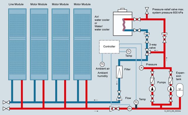
Example of a drive line-up with SINAMICS S120 liquid-cooled units
Характеристика
Derating
Liquid-cooled SINAMICS S120 chassis format units are rated for an ambient temperature of 45 °C (113 °F) and installation altitudes up to 2000 m (6562 ft) above sea level. At ambient temperatures > 45 °C (113 °F), the output current must be reduced. Ambient temperatures above 50 °C (122 °F) are not permissible. At installation altitudes > 2000 m (6562 ft) above sea level, it must be taken into account that the air pressure, and therefore air density, decreases as the height increases. As a consequence, the cooling efficiency and the insulation capacity of the air also decrease.
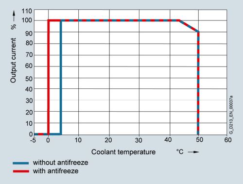
Current derating as a function of the temperature of the cooling liquid 1)
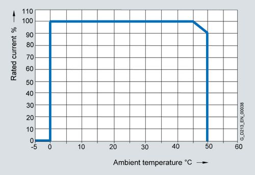
Current derating as a function of ambient temperature 1)
1) The factors of the two curves must not be multiplied. The highest value in each case must be assumed for the purposes of calculation, so that the derating factor in the worst-case scenario is 0.9.
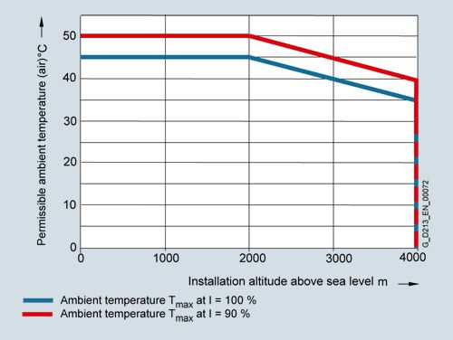
Permissible ambient temperature as a function of installation altitude
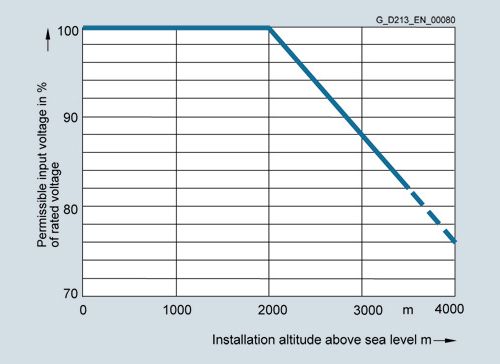
Voltage derating as a function of installation altitude
Current derating for Power Modules and Motor Modules in chassis format as a function of the pulse frequency
To reduce motor noise or to increase output frequency, the pulse frequency can be increased relative to the factory setting (1.25 kHz or 2 kHz). When the pulse frequency is increased, the derating factor of the output current must be taken into account. This derating factor must be applied to the currents specified in the technical specifications.
For additional information, please refer to the SINAMICS Low Voltage Engineering Manual.
The following tables list the rated output currents of the SINAMICS S120 Power Modules and Motor Modules with pulse frequency set in the factory as well as the current derating factors (permissible output currents referred to the rated output current) for higher pulse frequencies.
Derating factor of the output current as a function of the pulse frequency for units with a rated pulse frequency of 2 kHz
Power Module
Motor ModuleType rating
at 400 VOutput current at 2 kHz
Derating factor at pulse frequency
6SL3315-...
6SL3325-...kW (hp)
A
2.5 kHz
4 kHz
5 kHz
7.5 kHz
8 kHz
380 ... 480 V 3 AC
1TE32-1AA3
110 (150)
210
95 %
82 %
74 %
54 %
50 %
1TE32-6AA3
132 (200)
260
95 %
83 %
74 %
54 %
50 %
1TE33-1AA3
160 (250)
310
97 %
88 %
78 %
54 %
50 %
1TE35-0AA3
250 (400)
490
94 %
78 %
71 %
53 %
50 %
1TE41-4AS3 1)
800 (1000)
1330
88 %
55 %
–
–
–
1) This Motor Module has been specifically designed for loads demanding a high dynamic performance. The derating factor kIGBT and the derating characteristics can be ignored (see section “Duty cycles” in the SINAMICS Low Voltage Engineering Manual).
Derating factor of the output current as a function of the pulse frequency for units with a rated pulse frequency of 1.25 kHz
Motor Module
Type rating at 400 V or 690 V
Output current at 1.25 kHz
Derating factor at pulse frequency
6SL3325-...
kW (hp)
A
2 kHz
2.5 kHz
4 kHz
5 kHz
7.5 kHz
380 ... 480 V 3 AC
1TE36-1AA3
315 (500)
605
83 %
72 %
64 %
60 %
40 %
1TE37-5AA3
400 (600)
745
83 %
72 %
64 %
60 %
40 %
1TE38-4AA3
450 (700)
840
87 %
79 %
64 %
60 %
40 %
1TE41-0AA3
560 (800)
985
92 %
87 %
70 %
60 %
50 %
1TE41-2AA3
710 (1000)
1260
92 %
87 %
70 %
60 %
50 %
1TE41-4AA3
800 (1150)
1405
97 %
95 %
74 %
60 %
50 %
500 ... 690 V 3 AC
1TG31-0AA3
90 (75)
100
92 %
88 %
71 %
60 %
40 %
1TG31-5AA3
132 (150)
150
90 %
84 %
66 %
55 %
35 %
1TG32-2AA3
200 (200)
215
92 %
87 %
70 %
60 %
40 %
1TG33-3AA3
315 (300)
330
89 %
82 %
65 %
55 %
40 %
1TG34-7AA3
450 (450)
465
92 %
87 %
67 %
55 %
35 %
1TG35-8AA3
560 (600)
575
91 %
85 %
64 %
50 %
35 %
1TG37-4AA3
710 (700)
735
84 %
74 %
53 %
40 %
25 %
1TG38-0AA3 2)
800 (800)
810
82 %
71 %
52 %
40 %
25 %
1TG38-1AA3
800 (800)
810
97 %
95 %
71 %
55 %
35 %
1TG41-0AA3
1000 (1000)
1025
91 %
86 %
64 %
50 %
30 %
1TG41-3AA3
1200 (1250)
1270
87 %
79 %
55 %
40 %
25 %
1TG41-6AA3
1500 (1500)
1560
87 %
79 %
55 %
40 %
25 %
2) The Motor Module 6SL3325-1TG38-0AA3 is optimized for low overload; with an increased pulse frequency, the derating factor is higher than for the Motor Module 6SL3325-1TG38-1AA3.
The following tables list the maximum achievable output frequency as a function of the pulse frequency.
Maximum output frequencies achieved by increasing the pulse frequency in Vector mode
Pulse frequency
Max. achievable output frequency
1.25 kHz
100 Hz
2 kHz
160 Hz
2.5 kHz
200 Hz
4 kHz
320 Hz
5 kHz
400 Hz
Maximum output frequencies achieved by increasing the pulse frequency in Servo mode
Pulse frequency
Max. achievable output frequency
2 kHz
300 Hz
4 kHz
300/550 Hz 3)
3) Higher frequencies on request.For further information seehttps://support.industry.siemens.com/cs/document/104020669
Pressure drop

Pressure drop for liquid-cooled built-in units in chassis format
The pressure drop characteristics are valid for water. If antifreeze is used, the characteristics typically shift to the left.
For further information, please refer to the SINAMICS Low Voltage Engineering Manual.
Overload capability
Liquid-cooled SINAMICS S120 units have an overload reserve, e.g. to handle breakaway torques. If larger surge loads occur, this must be taken into account in the configuration. For drives with overload requirements, the appropriate base load current must, therefore, be used as a basis for the required load.
The permissible overload levels are valid under the prerequisite that the drive units are operated with their base-load current before and after the overload condition based on a duty cycle duration of 300 s.
For temporary, periodic duty cycles with high variations of load within the duty cycle, the relevant sections of the SINAMICS Low Voltage Engineering Manual must be observed.
Power Modules and Motor Modules
The base-load current for a low overload IL is the basis for a duty cycle of 110 % for 60 s or 150 % for 10 s.
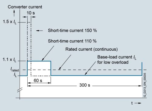
Low overload
The base-load current IH for a high overload is based on a duty cycle of 150 % for 60 s or 160 % for 10 s.

High overload
Line Modules
The base-load current for a high overload IH DC is the basis for a duty cycle of 150 % for 60 s or Imax DC for 5 s.
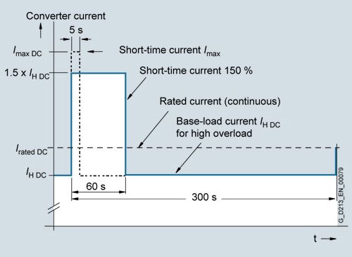
High overload
Технические данные
General technical specifications
Unless clearly specified otherwise, the following technical data are valid for all the following components of the liquid-cooled SINAMICS S120 drive system in the chassis format.
Electrical specifications
Rated voltages
380 ... 480 V 3 AC ±10 % (-15 % <1 min)
500 ... 690 V 3 AC ±10 % (-15 % <1 min)
Line supply types
Grounded TN/TT systems and non-grounded IT systems
Line frequency
47 ... 63 Hz
Overvoltage category
III to EN 61800‑5‑1
Electronics power supply
24 V DC, -15 % +20 %
implemented as PELV circuit in accordance with EN 61800-5-1
Ground = negative pole grounded via the electronicsRated short-circuit current
per IEC, in conjunction with the specified fuses or circuit breakers
- 1.1 ... 447 kW
65 kA
- 448 ... 671 kW
84 kA
- 672 ... 1193 kW
170 kA
- > 1194 kW
200 kA
Rated short-circuit current SCCR
(Short Circuit Current Rating)according to UL508C (up to 600 V), in conjunction with the specified fuses or circuit breakers
- 1.1 ... 447 kW
65 kA
- 448 ... 671 kW
84 kA
- 672 ... 1193 kW
170 kA
- > 1194 kW
200 kA
Control method
Vector/Servo control with and without encoder or V/f control
Fixed speeds
15 fixed speeds plus 1 minimum speed, parameterizable (in the default setting, 3 fixed setpoints plus 1 minimum speed are selectable using terminal block/PROFIBUS/PROFINET)
Skippable speed ranges
4, parameterizable
Setpoint resolution
0.001 rpm digital (14 bits + sign)
12 bits analogBraking operation
With Active Line Modules, four-quadrant operation as standard (energy recovery).
With Basic Line Modules, two-quadrant operation as standard, braking by means of an optional braking chopper, or alternatively by a Motor Module.
Mechanical specifications
Degree of protection
IP00 (IP20, without taking into account the connecting busbars)
Protection class
I acc. to EN 61800‑5‑1
Touch protection
EN 50274/DGUV regulation 3 when used as intended
Cooling method
Liquid cooling with integrated heat exchanger in aluminum or stainless steel version
Ambient conditions
Storage 1)
Transport 1)
Operation
Ambient temperature (air)
-25 ... +55 °C (-13 ... +131 °F)
Class 1K4
acc. to EN 60721‑3‑1-25 ... +70 °C (-13 ... +158 °F)
Class 2K4
acc. to EN 60721‑3‑2Line-side components, Power Modules, Line Modules and Motor Modules:
0 ... 45 °C (32 ... 113 °F)without derating
>45 ... 50 °C (113 ... 122 °F) see derating characteristicsControl Units, supplementary system components, and Sensor Modules:
0 ... 55 °C (32 ... 131 °F) (for operation in a control cabinet)DC link components and motor-side components:
0 ... 55 °C (32 ... 131 °F)Relative humidity
Condensation, splashwater, and ice formation not permitted (EN 60204, Part 1)
5 ... 95 %
Class 1K4
acc. to EN 60721‑3‑1Max. 95 % at 40 °C (104 °F)
Class 2K4
acc. to EN 60721‑3‑25 ... 95 %
Class 3K3
acc. to EN 60721‑3‑3Environmental class/harmful chemical substances
Class 1C2
acc. to EN 60721‑3‑1Class 2C2
acc. to EN 60721‑3‑2Class 3C2
acc. to EN 60721‑3‑3Organic/biological influences
Class 1B1
acc. to EN 60721‑3‑1Class 2B1
acc. to EN 60721‑3‑2Class 3B1
acc. to EN 60721‑3‑3Degree of pollution
2 acc. to IEC/EN 61800‑5‑1
Installation altitude
Up to 2000 m (6562 ft) above sea level without derating,
> 2000 m (6562 ft) above sea level, refer to the derating dataMechanical stability
Storage 1)
Transport 1)
Operation
Vibratory load
Class 2M2
acc. to EN 60721-3-2Test values
acc. to EN 60068‑2‑6 test Fc:- 10 ... 58 Hz with constant deflection 0.075 mm
- 58 ... 150 Hz with constant acceleration 9.81 m/s2 (1 × g)
Shock load
Class 2M2
acc. to EN 60721-3-2Test values
acc. to EN 60068‑2‑27 test Ea:
98 m/s2 (10 × g)/20 msCompliance with standards
Certificates of suitability
CE (EMC Directive No. 2014/30/EU, Low Voltage Directive No. 2014/35/EU and Machinery Directive 2006/42/EC for functional safety)
RCM
cULus (only for devices connected to line supply voltages 380 ... 480 V 3 AC and 500 ... 600 V 3 AC)Electromagnetic compatibility
Built-in units SINAMICS S120 chassis format can be operated in the second environment, Category C3/C2 according to EMC product standard EN 61800‑3.
For further information, see section Tools and configuring.
1) In transport packaging.
Deviations from the specified class are underlined.
Cooling circuit and coolant quality
The following tables and sections describe the quality requirements of the coolant used in the liquid-cooled SINAMICS S120 drive system in chassis format.
Cooling circuit
- System pressure with reference to atmospheric pressure, max.
600 kPa
- Pressure drop at rated volumetric flow
70 kPa
- Recommended pressure range
80 ... 200 kPa
- Inlet temperature of liquid coolant
Dependent on ambient temperature, no condensation permitted
0 ... 45° C (32 ... 113 °F) without derating
>45 … 50 °C (113 ... 122 °F), see derating data
Anti-freeze essential for temperature range between 0 °C (32 °F) and 5 °C (41 °F)
Coolant quality
- Coolant basis for aluminum heat sinks
Distilled, demineralized, completely desalinated water or deionized water with reduced electrical conductivity ISO 3696, quality 3 or based on IEC 60993
- Electrical conductivity
<30 μS/cm (3 mS/m)
- pH value
5 ... 8
- Components that can be oxidized as oxygen content
< 30 mg/l
- Residue after vaporization and drying at 110 °C
<10 mg/kg
- Coolant basis for stainless steel heat sinks
Filtered drinking water
- Electrical conductivity
<2000 μS/cm
- pH value
6.5 ... 9
- Chloride ions
<200 mg/l
- Sulfate ions
<240 mg/l
- Nitrate ions
< 50 mg/l
- Total hardness
< 1.7 mmol/l
- Dissolved substances
< 340 mg/l
- Size of entrained particles
< 100 μm
The coolant definition specified here should only be considered as recommendation. For units that have been shipped, the information and data provided in the equipment manual supplied should be observed!
Antifreeze and inhibitors
Antifreeze
Antifrogen N
Antifrogen L
DOWCAL 100
Manufacturer
Clariant
Clariant
DOW
Chemical base
Ethylene glycol
Propylene glycol
Ethylene glycol
Minimum concentration
20 %
25 %
20 %
Anti-freeze agent with minimum concentration
-10 °C
-10 °C
-10 °C
Maximum concentration
45 %
48 %
44 %
Anti-freeze agent with maximum concentration
-30 °C
-30 °C
-30 °C
Inhibitor content
Contains inhibitors with nitrites
Contains inhibitors that are free of nitrates, amines, borates and phosphates
Contains inhibitors that are free of nitrates, amines and phosphates
Biocide action with a concentration of
> 20 %
> 30 %
> 20 %
Biocides prevent corrosion that is caused by slime-forming, corrosive or iron-depositing bacteria. These can occur in closed cooling circuits with low water hardness and in open cooling circuits. Biocides must always be selected according to the relevant bacterial risks. Compatibility with inhibitors or antifreeze used with them must be checked on a case-by-case basis.
Inhibitors
Antifrogen N
ANTICORIT S 2000 A
Manufacturer
Clariant
Fuchs
Chemical base
Ethylene glycol
–
Minimum concentration
20 %
4 %
Maximum concentration
45 %
5 %
Recommended service
The manufacturer of the antifreeze/inhibitor should analyze the coolant at least once per annum. The concentration and boundary conditions of the antifreeze/inhibitor should be checked. It may be necessary to correct the concentration on the plant side.
Protection against condensation
With liquid-cooled units, warm air can condense on the cold surfaces of heat sinks, pipes and hoses. This condensation depends on the air humidity and the temperature difference between the ambient air and the coolant.
The water which is produced as a result of condensation can cause corrosion as well as electrical damage such as creepage shorts and flashovers. As the SINAMICS units cannot prevent condensation if it is caused by the prevailing climatic conditions, any potential risk of condensation must be prevented by appropriate engineering or by precautionary measures implemented by the customer. These measures include the following:
- a fixed coolant temperature that has been adjusted to the expected air humidity or ambient temperature ensures that critical differences between the coolant and ambient air temperatures do not develop or
- temperature regulation of the coolant as a function of the ambient air temperature
The temperature at which water vapor contained in the air condenses into water is known as the dew point. To prevent condensation reliably, the coolant temperature must always be higher than the dew point.
The table below specifies the dew point as a function of room temperature T and relative air humidity Φ for an atmospheric pressure of 100 kPa (1 bar). This corresponds to an installation altitude of 0 up to approximately 500 m (1640 ft) above sea level. Since the dew point drops as the air pressure decreases, the dew point values at higher installation altitudes are lower than the specified table values. It is therefore the safest approach to engineer the coolant temperature according to the values in the table for an installation altitude of zero.
Ambient temperature
Relative air humidity Φ
T
20 %
30 %
40 %
50 %
60 %
70 %
80 %
85 %
90 %
95 %
100 %
10 °C (50 °F)
<0 °C (32 °F)
<0 °C (32 °F)
<0 °C (32 °F)
0.2 °C (32.4 °F)
2.7 °C (36.9 °F)
4.8 °C (40.6 °F)
6.7 °C (44.1 °F)
7.6 °C (45.7 °F)
8.4 °C (47.1 °F)
9.2 °C (48.6 °F)
10 °C (50 °F)
20 °C (68 °F)
<0 °C (32 °F)
2 °C (35.6 °F)
6 °C (42.8 °F)
9.3 °C (48.7 °F)
12 °C (53.6 °F)
14.3 °C (57.7 °F)
16.4 °C (61.5 °F)
17.4 °C (63.3 °F)
18.3 °C (64.9 °F)
19.1 °C (66.4 °F)
20 °C (68 °F)
25 °C (77 °F)
0.6 °C (33.1 °F)
6.3 °C (43.3 °F)
10.5 °C (50.9 °F)
13.8 °C (56.8 °F)
16.7 °C (62.1 °F)
19.1 °C (66.4 °F)
21.2 °C (70.2 °F)
22.2 °C (72 °F)
23.2 °C (73.8 °F)
24.1 °C (75.4 °F)
24.9 °C (76.8 °F)
30 °C (86 °F)
4.7 °C (40.5 °F)
10.5 °C (50.9 °F)
14.9 °C (58.8 °F)
18.4 °C (65.1 °F)
21.3 °C (70.3 °F)
23.8 °C (74.8 °F)
26.1 °C (79 °F)
27.1 °C (80.8 °F)
28.1 °C (82.6 °F)
29 °C (84.2 °F)
29.9 °C (85.8 °F)
35 °C (95 °F)
8.7 °C (47.7 °F)
14.8 °C (58.6 °F)
19.3 °C (66.7 °F)
22.9 °C (73.2 °F)
26 °C (78.8 °F)
28.6 °C (83.5 °F)
30.9 °C (87.6 °F)
32 °C (89.6 °F)
33 °C (91.4 °F)
34 °C (93.2 °F)
34.9 °C (94.8 °F)
40 °C (104 °F)
12.8 °C (55 °F)
19.1 °C (66.4 °F)
23.7 °C (74.7 °F)
27.5 °C (81.5 °F)
30.6 °C (87.1 °F)
33.4 °C (92.1 °F)
35.8 °C (96.4 °F)
36.9 °C (98.4 °F)
37.9 °C (100.2 °F)
38.9 °C (102 °F)
39.9 °C (103.8 °F)
45 °C (113 °F)
16.8 °C (62.2 °F)
23.3 °C (73.9 °F)
28.2 °C (82.8 °F)
32 °C (89.6 °F)
35.3 °C (95.5 °F)
38.1 °C (101.6 °F)
40.6 °C (105.1 °F)
41.8 °C (107.2 °F)
42.9 °C (109.2 °F)
43.9 °C (111 °F)
44.9 °C (112.8 °F)
50 °C (122 °F)
20.8 °C (69.4 °F)
27.5 °C (81.5 °F)
32.6 °C (90.7 °F)
36.6 °C (97.9 °F)
40 °C (104 °F)
42.9 °C (109.2 °F)
45.5 °C (113.9 °F)
46.6 °C (115.9 °F)
47.8 °C (118 °F)
48.9 °C (120 °F)
49.9 °C (121.8 °F)
A detailed description of the cooling circuits and the recommended coolant is given in the SINAMICS Low Voltage Engineering Manual.