
- Каталог оборудования Siemens
- Каталог продуктов Siemens Industry
- Приводная техника
- Преобразователи
- Стандартные преобразователи
- Общая информация о базовых преобразователях SINAMICS V
- Преобразователи частоты общего назначения SINAMICS G
- Высокопроизводительные преобразователи SINAMICS S
- Сервопреобразователь SINAMICS S110
- SINAMICS S120
- SINAMICS S120M distributed servo drive
- SINAMICS S120 Combi
- SINAMICS S120 Chassis Format Units
- SINAMICS S120 Cabinet ModulesAir-cooled unitsLiquid-cooled unitsOptionsSupplementary system componentsOrder-specific integration engineeringCustomized solutions
- SINAMICS S120 Cabinet Modules
- SINAMICS S150 converter cabinet units
- MICROMASTER
- SIPLUS POSMO A
- SIMODRIVE POSMO
- LOHER DYNAVERT Drive System
- Преобразователи на среднее напряжение
- Преобразователи постоянного тока
- Стандартные преобразователи
- Двигатели переменного тока
- Generators
- Мотор-редукторы
- Flender Gear Units
- Couplings
- Инструментальное программное обеспечение
- Дополнительные компоненты
- Преобразователи
- Техника автоматизации
- Energy
- Автоматизация и безопасность зданий
- Низковольтная коммутационная техника
- Технология безопасности
- Системные решения и продукты для отраслей
- Сервис
- Приводная техника
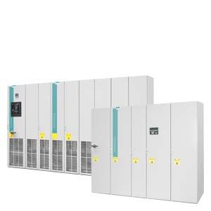
SINAMICS S120 Cabinet Modules
- Информационные материалы
Информационные материалы

SINAMICS S120 Cabinet Modules, air-cooled and liquid-cooled
SINAMICS S120 Cabinet Modules are the components of a modular cabinet system for multi-motor drives with a central supply infeed and a common DC link busbar, as used, for example, in the process industry, automotive industry, metal processing industry as well as in the crane and mining domains. They are available in air-cooled or liquid-cooled versions. As standard, they are installed side by side in a row. Other installation types (e.g. back to back) are possible on request. SINAMICS S120 Cabinet Modules include the chassis units from the SINAMICS S120 series in booksize format (Motor Modules) and chassis format, thus making the range an ideal supplement to the SINAMICS G150 and SINAMICS S150 cabinet converter series for single-motor drives.
All drive components, from the supply infeed to the motor-side inverters, are configured in a clear, compact layout in the individual Cabinet Modules. They can be flexibly combined and optimally adapted to customer-specific requirements thanks to a comprehensive array of options.
The main components of the air-cooled system are as follows:
- Line Connection Modules with line-side components such as contactors, fuses and circuit breakers, as well as line reactors for Basic Line Modules
- The following types of infeed Line Modules:
- Basic Line Modules for two-quadrant operation
- Smart Line Modules for four-quadrant operation
- Active Line Modules for four-quadrant operation with negligible line harmonics
- Central Braking Modules for braking operation
- The following types of Motor Modules:
- Booksize Cabinet Kit
- Chassis
- Control Units
- Auxiliary Power Supply Modules to supply the auxiliary power supply system
The main components of the liquid-cooled system are as follows:
- Active Line Connection Modules as a combination of Line Connection Module and Active Line Module with an Active Interface Module
- Basic Line Connection Modules as a combination of a Line Connection Module and a Basic Line Module
- Motor Modules
- Control Units
- Heat Exchanger Modules with pumps, closed-loop control and a heat exchanger between the deionized water and raw water circuits
Standardized interfaces for both the power and the control connections facilitate engineering and installation. Communication between the power modules and the central Control Unit takes place via DRIVE‑CLiQ, the internal drive serial interface.

Example of a drive line-up with SINAMICS S120 Cabinet Modules for a multi-motor drive
The following tables provide an overview of the voltage ranges and power ratings of the available SINAMICS S120 Cabinet Modules.
Voltage ranges and powers for air-cooled SINAMICS S120 Cabinet Modules
Line voltage
Input current
DC link voltage
DC link current
Output current
Power range of single modules
Line Connection Modules 1)
380 ... 480 V 3 AC
250 ... 3200 A
–
–
–
–
500 ... 690 V 3 AC
280 ... 3200 A
–
–
–
–
Basic Line Modules 1)
380 ... 480 V 3 AC
365 ... 1630 A
510 ... 650 V
420 ... 1880 A
–
200 ... 900 kW
500 ... 690 V 3 AC
260 ... 1580 A
675 ... 930 V
300 ... 1880 A
–
250 ... 1500 kW
Smart Line Modules 1)
380 ... 480 V 3 AC
463 ... 1430 A
510 ... 650 V
550 ... 1700 A
–
250 ... 800 kW
500 ... 690 V 3 AC
463 ... 1430 A
675 ... 930 V
550 ... 1700 A
–
450 ... 1400 kW
Active Line Modules 1)
380 ... 480 V 3 AC
210 ... 1405 A
540 ... 720 V
235 … 1574 A
–
132 ... 900 kW
500 ... 690 V 3 AC
575 ... 1270 A
710 ... 1035 V
644 ... 1422 A
–
560 ... 1400 kW
Motor Modules booksize
380 ... 480 V 3 AC
–
510 ... 720 V
–
9 ... 132 A
4.8 ... 71 kW
Motor Modules chassis 1)
380 ... 480 V 3 AC
–
510 ... 720 V
–
210 ... 1405 A
110 ... 800 kW
500 ... 690 V 3 AC
–
675 ... 1035 V
–
85 ... 1270 A
75 ... 1200 kW
Central Braking Modules 1)
380 ... 480 V 3 AC
–
510 ... 720 V
–
–
500 ... 1000 kW
500 … 600 V 3 AC
–
675 ... 900 V
–
–
550 ... 1100 kW
660 … 690 V 3 AC
–
890 ... 1035 V
–
–
630 ... 1200 kW
Auxiliary Power Supply Modules
380 ... 690 V 3 AC
125 ... 250 A
–
–
–
–
1) The power can be increased by connecting up to four identical modules in parallel.
Voltage ranges and power ratings for liquid-cooled SINAMICS S120 Cabinet Modules
Line voltage
Input current
DC link voltage
DC link current
Output current
Power range of single modules
Basic Line Connection Modules 1)
380 ... 480 V 3 AC
610 ... 1420 A
510 ... 650 V
740 ... 1730 A
–
360 ... 830 kW
500 ... 690 V 3 AC
340 ... 1350 A
675 ... 930 V
420 ... 1650 A
–
355 ... 1370 kW
Active Line Connection Modules 1)
380 ... 480 V 3 AC
985 ... 1405 A
540 ... 720 V
1100 ... 1573 A
–
630 ... 900 kW
500 ... 690 V 3 AC
1025 ... 1560 A
710 ... 1035 V
1147 ... 1740 A
–
1100 ... 1700 kW
Motor Modules 1)
380 ... 480 V 3 AC
–
510 ... 720 V
–
605 ... 1405 A
315 ... 800 kW
500 ... 690 V 3 AC
–
675 ... 1035 V
–
465 ... 1560 A
450 ... 1500 kW
1) The power can be increased by connecting up to four identical modules in parallel.
Область применения
SINAMICS S120 Cabinet Modules have been specially developed to allow simple configuration of multi-motor systems. They are used for applications where several motors must be coordinated to realize a drive task as multi-motor drives in a drive line-up. Examples of such applications include:
- Packaging machines
- Plastics processing machines
- Textile machines
- Presses and punches
- Rolling mill drives
- Hoists and cranes
- Printing and paper machines
- Vehicle and gearbox test stands
- Test stand applications
- Machines used in the woodworking, glass and ceramics industries
- Handling and assembly systems
- Machine tools
High-power single drives (parallel connection) can also be implemented with Cabinet Modules.
Дизайн
They have been designed according to the zone concept principle and therefore offer the highest possible level of operational reliability. EMC measures have been rigorously implemented. With the help of simulated conditions, partitions have been designed to act as air guides and heat dissipation units.
Special measures used in the construction of the cabinets ensure that they remain mechanically durable over their entire life cycle.
Attention has been paid to providing a wide range of cable routing options and special design concepts are applied consistently to broaden the scope of application and simplify service. The units have all the necessary connections and connecting elements. Thanks to their carefully considered configuration concept, cabinets are shipped in a ready-to-connect state or, in the case of multiple transport units, have been prepared for quick assembly. An extensive spectrum of options designed to adapt the units to a variety of different applications facilitates the selection process.
All components, from individual parts to the ready-to-connect cabinet, undergo rigorous testing throughout the entire production process. This guarantees a high level of functional reliability during installation and commissioning, as well as in operation.
Replaceable components have been designed so that they can be quickly and easily replaced. In addition, the "Spares On Web" Internet tool makes it easy to view the spare parts that are available for the particular order at all times 1).
1) The properties of the SINAMICS S120 Cabinet Modules described in this catalog are not transferable to cabinet units constructed to meet the requirements of specific applications.
System design
Line Modules are coupled with the various Motor Modules by means of prefabricated busbar sets with different current carrying capacities.
All standard busbars, as well as electronics components, are protected against environmental influences. This is achieved through the use of nickel-plated copper bars and painted modules throughout.
A special, standard auxiliary power supply system supplies the individual Cabinet Modules with the required auxiliary voltages for the power components, fans and 24 V loads.
These voltages are preferably generated using an auxiliary power supply module. Additional supply possibilities are available using the K76 option (auxiliary power supply generation in the Line Connection Module) or using an external supply in the auxiliary power supply system.
The auxiliary power supply system comprises an auxiliary power supply module with two terminal blocks (air cooling) and one auxiliary voltage terminal (liquid cooling) and a 24 V DC fuse as well as the required connecting cables. It is supplied completely assembled and ready to operate. Only the cable connections to the adjacent Cabinet Module must be established on-site.
Communication between the Control Unit, power units and other active SINAMICS components is realized via DRIVE‑CLiQ connections.
DRIVE‑CLiQ is an internal serial interface of the drive that enables fast and easy configuration of the complete drive line-up with prefabricated cables in varying lengths.
The Cabinet Modules can be optionally supplied in pre-configured transport units up to a total length of 2400 mm. This option is particularly recommended in air-cooled Cabinet Modules for Line Modules together with Line Connection Modules since, in this case, the Line Connection Module must be equipped with a pre-charging DC link or line reactors (depending on the type of Line Module), in addition to the electrical interface (busbar). For liquid-cooled Cabinet Modules, delivery in transport units has the advantage that the tube system of the cooling system can be implemented completely without couplings. Transport units thus enable the various devices to be quickly and easily assembled on-site.
Coated modules
The following devices are equipped with coated modules as standard:
- Booksize format units
- Chassis format units
- Control Units
- Sensor Modules
- Terminal Modules
- Advanced Operator Panel (AOP30)
The coating on the modules protects the sensitive SMD components against corrosive gases, chemically active dust and moisture.
Nickel-plated busbars
All of the copper busbars used in the converter cabinets are nickel-plated to achieve the best possible immunity to environmental effects. Furthermore, there is no need to clean the contacts on the customer terminals as otherwise required for bare copper connections.
Note:
With some options, parts of the copper busbars cannot be nickel-plated for technical reasons.
PE bars
The Cabinet Modules are delivered with a PE bar as standard. It is used to connect and fasten PE conductors.
Degrees of protection of Cabinet Modules
The EN 60529 standard covers the protection of electrical equipment by means of housings, covers or equivalent, and includes:
- Protection of persons against accidental contact with live or moving parts within the housing and protection of the equipment against the ingress of solid foreign bodies (touch protection and protection against ingress of solid foreign bodies)
- Protection of the equipment against the ingress of water (water protection)
- Abbreviations for the internationally agreed degrees of protection
The degrees of protection are specified by abbreviations comprising the code letters IP and two digits.
Degree of protection
First code number
(touch protection and protection against solid foreign bodies)
Second code number
(protection of the equipment against the ingress of water)
IP20
(Standard for air-cooled version)Protected against solid foreign bodies
diameter ≥ 12.5 mmNo water protection
IP21
(Standard for liquid-cooled version, option M21 for air-cooled version)Protected against solid foreign bodies
diameter ≥ 12.5 mmProtected against drip water
Vertically falling water drops shall not have a harmful effect.
IP23
(Option M23)
Protected against solid foreign bodies
diameter ≥ 12.5 mmProtected against spray water
Water sprayed on both sides of the vertical at an angle of up to 60° shall not have a harmful effect.
IP43
(Option M43)
Protected against solid foreign bodies
diameter ≥ 1 mmProtected against spray water
Water sprayed on both sides of the vertical at an angle of up to 60° shall not have a harmful effect.
IP54
(Air-cooled version only)(Option M54)
Dust protected
Ingress of dust is not totally prevented, but dust must not be allowed to enter in such quantities that the functioning or safety of the equipment is impaired.
Complete touch protection
Protected against splash water
Water splashing onto the enclosure from any direction shall not have a harmful effect.
IP55
(Liquid-cooled version only)(Option M55)
Dust protected
Ingress of dust is not totally prevented, but dust must not be allowed to enter in such quantities that the functioning or safety of the equipment is impaired.
Complete touch protection
Protected against water jet (nozzle)
Water projected by a nozzle against the enclosure from any direction shall not have a harmful effect.
Air-cooled Cabinet Modules meet degree of protection IP20, liquid-cooled Cabinet Modules degree of protection IP21, as standard. The other degrees of protection outlined here are available as an option.
Функции
Communication with higher-level controller and customer terminal block
As the customer interface to the control system, a PROFIBUS interface is available on the CU320-2 DP Control Unit or a PROFINET interface on the CU320-2 PN Control Unit as standard.
In the case of the air-cooled Cabinet Modules, the inputs and outputs available as standard on the customer terminal block -X55, which are easy to access and easy to connect up, can be provided.
In the case of the liquid-cooled Cabinet Modules, the components are directly connected.For further information, please refer to the SINAMICS Low Voltage Engineering Manual.
Open-loop and closed-loop control functions
SINAMICS S120 can use a dynamic, high-precision closed-loop vector control (drive object type VECTOR), or a highly dynamic closed-loop servo control (drive object type SERVO).
Software and protective functions
The software functions available as standard are described below:
Software and protective functions
Description
Setpoint input
The setpoint can be specified both internally and externally; internally as a fixed setpoint, motorized potentiometer setpoint or jog setpoint, externally via the communications interface or an analog input. The internal fixed setpoint and the motorized potentiometer setpoint can be switched or adjusted via control commands from any interface.
Motor identification
The automatic motor identification function makes commissioning faster and easier and optimizes closed-loop control of the drive.
Ramp-function generator
A user-friendly ramp-function generator with separately adjustable ramp-up and ramp-down times, together with adjustable rounding times in the lower and upper speed ranges, allows the drive to be smoothly accelerated and braked. This results in a good speed control response and plays its role in reducing the stress on the mechanical system. The down ramp can be parameterized separately for a quick stop.
Vdc max controller
The Vdc max controller automatically prevents overvoltages in the DC link, if the set down ramp is too short, for example. This may also extend the set ramp-down time.
Note: This function only makes sense for single-axis applications.
Kinetic buffering (KIP)
For brief line supply failures, the kinetic energy of the rotating drive is used to buffer the DC link and therefore prevents fault trips. The drive converter remains operational as long as the drive can provide regenerative energy as a result of its motion and the DC link voltage does not drop below the shutdown threshold. When the line supply recovers within this time, the drive is again bumplessly accelerated up to its setpoint speed.
Automatic restart
The automatic restart switches the drive on again when the power is restored after a power failure, and ramps up to the current speed setpoint.
Flying restart
The flying restart function allows the converter to be switched to a motor that is still turning. With the voltage sensing capability provided by the optional VSM10, the flying restart time for large induction motors can be significantly reduced because the motor does not need to be de-magnetized.
Technology controller
Using the technology controller (PID controller) function module, level or flow controls and complex tension controls can be implemented, for example. The existing D component can act both on the system deviation well as on the actual value (factory setting). The P, I, and D components are set separately.
Free function blocks
Using the freely programmable function blocks, it is easy to implement logic and arithmetic functions for controlling the SINAMICS drive. The blocks can be programmed at the operator panel or the STARTER commissioning tool.
Drive Control Chart (DCC)
Drive Control Chart (DCC) is an additional tool for the easy configuration of technological functions for SINAMICS. The block library contains a large selection of control, arithmetic and logic blocks as well as extensive open-loop and closed-loop control functions. The user-friendly DCC editor enables easy graphics-based configuration, allows control loop structures to be clearly represented and provides a high degree of reusability of charts that have already been created. DCC is an add-on for the STARTER commissioning tool (→ Tools and Engineering).
I2t sensing for motor protection
A motor model stored in the converter software calculates the motor temperature based on the current speed and load. More exact measurement of the temperature, which also takes into account the influence of the ambient temperature, is possible by means of direct temperature measurement using KTY84 sensors in the motor winding.
Motor temperature evaluation
Motor protection by evaluating a KTY84, PTC or Pt100 temperature sensor. When a KTY84 temperature sensor is connected, the limit values can be set for alarm or shutdown. When a PTC thermistor is connected, the system reaction to triggering of the thermistor (alarm or trip) can be defined.
Motor blocking protection
A blocked motor is detected and protected against thermal overloading by a fault trip.
Brake control
“Simple brake control” for controlling holding brakes:
The holding brake is used to secure drives against unwanted motion when deactivated.The "extended braking control" function module allows complex braking control, for example, for motor holding brakes and operational brakes.
In the case of brakes with feedback signal, the brake control reacts to the feedback contacts of the brake.Write protection
Write protection to prevent unintentional changing of the setting parameters (without password function).
Know-how protection
Know‑how protection for encrypting stored data, e.g. to protect expert configuring knowledge, and to protect against modification and duplication (with password function).
Web server
The integrated web server provides information about the drive unit via its web pages. The web server is accessed using a web browser via unsecured (http) or secured transfer protocol (https).
Power unit protection
Power unit protection
Description
Ground fault monitoring at the output
A ground fault at the output is detected by a total current monitor and results in shutdown in grounded systems.
Electronic short-circuit protection at the output
A short-circuit at the output (e.g. at the converter output terminals, in the motor cable or in the motor terminal box) is detected and the converter shuts down with a "fault".
Thermal overload protection
An alarm is issued first when the overtemperature threshold responds. If the temperature continues to rise, the unit either shuts down or independently adjusts the pulse frequency or output current so that thermal load is reduced. Once the cause of the fault has been eliminated (e.g. cooling has been improved), the original operating values are automatically resumed.
Особенности
The outstanding system features of the SINAMICS S120 Cabinet Modules provide the following advantages:
- Process optimization with minimum outlay
- A standard PROFIBUS or PROFINET interface and various analog and digital interfaces enables easy integration into automation solutions
- Vector and servo control ensures that they fulfill the most exacting requirements regarding the accuracy and dynamic response of drives.
- High level of reliability and availability
- Individual modules and power components can be replaced quickly and easily, which ensures a higher level of plant availability
- Energy saving during operation
- The motor-side inverters are coupled via the common DC link and allow energy to be exchanged between motors that are motoring and generating. This means that energy is saved, there is less load on the supply infeed and line harmonics are reduced
- Generally the line infeed is only dimensioned for the maximum energy required when motoring or the maximum current required when motoring – and not the sum of the energy requirements of the Motor Modules connected to the DC link. As a consequence, for example, for conveyor belts or motor test stands with Motor Modules that are simultaneously operated in motoring and generating modes, a significantly smaller line infeed unit can be selected.
- Minimal operative, maintenance, and servicing costs
- Simple commissioning thanks to the menu-driven STARTER commissioning tool.
- Optional, menu-navigated AOP30 advanced operator panel with plain text display and bar-type display.
- All modules are easily accessible, making them extremely service friendly
- Space-saving design
- Environmentally-friendly operation
- The converters are exceptionally quiet and compact thanks to state-of-the-art IGBT power semiconductors and an innovative cooling concept
Технические данные
The most important directives and standards are listed below. These are used as basis for the SINAMICS S120 Cabinet Modules and they must be carefully observed to achieve an EMC-compliant configuration that is safe both in terms of functionally and in operation.
European directives
2006/95/EC
Low Voltage Directive:
Directive of the European Parliament and Council of December 12, 2006, on the approximation of the laws of the member states relating to electrical equipment designed for use within certain voltage limits2004/108/EC
EMC directive:
Directive of the European Parliament and Council of December 15, 2004, which repeals directive 89/336/EEC, on the approximation of laws of the member states relating to electromagnetic compatibility2006/42/EC
Machinery Directive:
Directive of the European Parliament and Council of May 17, 2006, on machinery and amending Directive 95/16/EC (recast).European standards
EN ISO 3744
Acoustics - Determination of sound power levels and sound energy levels of noise sources using sound pressure – Engineering methods for an essentially free acoustic field over a reflecting plane
EN ISO 13849‑1
Safety of machinery – safety-related parts of control systems;
Part 1: General principles for design (ISO 13849-1: 2006)EN 60146‑1‑1
Semiconductor converters – General requirements and line-commutated converters
Part 1-1: Specification of basic requirementsEN 60204‑1
Safety of machinery – Electrical equipment of machines;
Part 1: General requirementsEN 60529
Degrees of protection provided by enclosures (IP Code)
EN 61508‑1
Functional safety of electrical/electronic/programmable electronic safety-related systems
Part 1: General requirementsEN 61800‑2
Adjustable speed electrical power drive systems
Part 2: General requirements – Rating specifications for low voltage adjustable frequency AC power drive systemsEN 61800‑3
Adjustable speed electrical power drive systems
Part 3: EMC - requirements and specific test methodsEN 61800‑5‑1
Adjustable speed electrical power drive systems
Part 5: Safety requirements
Main section 1: Electrical and thermal requirementsEN 61800‑5‑2
Adjustable speed electrical power drive systems
Part 5-2: Safety requirements – Functional safety (IEC 61800‑5‑2: 2007)