- Каталог оборудования Siemens
- Каталог продуктов Siemens Industry
- Приводная техника
- Преобразователи
- Стандартные преобразователи
- Общая информация о базовых преобразователях SINAMICS V
- Преобразователи частоты общего назначения SINAMICS G
- Высокопроизводительные преобразователи SINAMICS S
- MICROMASTER
- SIPLUS POSMO A
- SIMODRIVE POSMO
- LOHER DYNAVERT Drive System
- Преобразователи на среднее напряжение
- Преобразователи постоянного тока
- Стандартные преобразователи
- Двигатели переменного тока
- Generators
- Мотор-редукторы
- Flender Gear Units
- Couplings
- Инструментальное программное обеспечение
- Дополнительные компоненты
- Преобразователи
- Техника автоматизации
- Energy
- Автоматизация и безопасность зданий
- Низковольтная коммутационная техника
- Технология безопасности
- Системные решения и продукты для отраслей
- Сервис
- Приводная техника

Options
- Информационные материалы
Информационные материалы
The following table provides an overview of all of the available options – and their assignment to the individual Cabinet Modules.
SINAMICS S120 Cabinet Modules
Air-cooled Cabinet Modules
Liquid-cooled Cabinet Modules
Order code
Options
Line Connection Module
Basic Line Module
Smart Line Module
Active Line Module with Active Interface Module
Motor Module Booksize (Cabinet Kit)
Motor Module Booksize (Base Cabinet)
Motor Module Chassis
Central Braking Module
Auxiliary Power Supply Module
Basic Line Connection Module
Active Line Connection Module
Motor Module
Heat Exchanger Module
G20 1)
CBC10 Communication Board
–
✓
✓
✓
✓
–
✓
–
–
✓
✓
✓
–
G33 1)
CBE20 Communication Board
–
✓
✓
✓
✓
–
✓
–
–
✓
✓
✓
–
G51
1 x TM150 temperature sensor evaluation unit
✓
–
–
–
–
–
–
–
–
✓
✓
✓
–
G52
2 x TM150 temperature sensor evaluation units
✓
–
–
–
–
–
–
–
–
✓
✓
✓
–
G53
3 x TM150 temperature sensor evaluation units
✓
–
–
–
–
–
–
–
–
✓
✓
–
–
G54
4 x TM150 temperature sensor evaluation units
✓
–
–
–
–
–
–
–
–
✓
✓
–
–
G56
Contactor monitoring
–
✓
✓
✓ 2)
–
–
–
–
–
–
–
–
–
G60 1)
TM31 Terminal Module
–
–
–
–
–
–
–
–
–
✓
✓
✓
–
G61 1)
Additional TM31 Terminal Module
–
–
–
–
–
–
–
–
–
✓
✓
✓
–
G62 1)
TB30 Terminal Board
–
✓
✓
✓
✓
–
–
–
–
✓
✓
✓
–
K01 to K05
Safety license for 1 to 5 axes
–
–
–
–
✓
–
✓
–
–
–
–
✓
–
K08 1)
AOP30 Advanced Operator Panel installed in the cabinet door
–
✓
✓
✓
✓
–
✓
–
–
✓
✓
✓
–
K46
SMC10 Sensor Module Cabinet-Mounted
–
–
–
–
✓
–
✓
–
–
–
–
✓
–
K48
SMC20 Sensor Module Cabinet-Mounted
–
–
–
–
✓
–
✓
–
–
–
–
✓
–
K50
SMC30 Sensor Module Cabinet-Mounted
–
–
–
–
✓
–
✓
–
–
–
–
✓
–
K51
VSM10 Voltage Sensing Module
–
–
–
–
✓
–
✓
–
–
–
–
✓
–
K52
Second SMC30 Sensor Module Cabinet-Mounted
–
–
–
–
✓
–
✓
–
–
–
–
✓
–
K70
Fan power supply
✓
–
–
–
–
–
–
–
–
–
–
–
–
K73
SITOP power supply 24 V DC
–
–
–
–
✓
–
–
–
–
–
–
–
–
K76
Auxiliary power generation (in the Line Connection Module)
✓
–
–
–
–
–
–
–
–
✓
✓
–
–
K82
Terminal module for controlling the Safe Torque Off and Safe Stop 1 safety functions
–
–
–
–
✓
–
✓
–
–
–
–
–
–
K87
TM54F Terminal Module
–
–
–
–
✓
–
✓
–
–
–
–
✓
–
K88
Safe Brake Adapter 230 V AC
–
–
–
–
–
–
✓
–
–
–
–
–
–
K90
CU320‑2 DP Control Unit
–
✓
✓
✓
✓
–
✓
–
–
✓
✓
✓
–
K94 1)
Performance expansion for CU320‑2 Control Unit
–
✓
✓
✓
✓
–
✓
–
–
✓
✓
✓
–
K95
CU320‑2 PN Control Unit
–
✓
✓
✓
✓
–
✓
–
–
✓
✓
✓
–
L00 3)
Use in the “first environment” according to EN 61800-3, Category C2 (TN/TT supply systems with grounded neutral point)
✓
–
–
–
–
–
–
–
–
–
–
–
–
L07
dv/dt filter plus Voltage Peak Limiter
–
–
–
–
–
–
✓
–
–
–
–
–
–
L08
Motor reactor
–
–
–
–
✓
–
✓
–
–
–
–
–
–
L09
2 motor reactors connected in series
–
–
–
–
✓
–
–
–
–
–
–
–
–
L10
dv/dt filter plus Voltage Peak Limiter
–
–
–
–
–
–
✓
–
–
–
–
–
–
L13
Main contactor (for supply currents of ≤ 800 A)
✓ 4)
–
–
–
–
–
–
–
–
✓ 4)
–
–
–
L21
Surge suppression
✓
–
–
–
–
–
–
–
–
✓
✓
–
–
L22
Scope of delivery without line reactor
✓ 5)
–
✓
–
–
–
–
–
–
✓
–
–
–
L25
Withdrawable circuit breaker in place of a fixed-mounted circuit breaker
✓ 6)
–
–
–
–
–
–
–
–
✓ 6)
✓ 6)
–
–
L34
Output-side circuit breaker (motor-driven)
–
–
–
–
–
–
✓
–
–
–
–
–
–
L37
DC interface incl. pre-charging circuit of the associated DC link capacitance
–
–
–
–
✓
–
✓
–
–
–
–
–
–
L40
Line filter monitoring
–
–
–
✓
–
–
–
–
–
–
✓
–
–
L41
Current transformer upstream of main circuit breaker
✓
–
–
–
–
–
–
–
–
✓
✓
–
–
L42
Line Connection Module for Active Line Modules
✓
–
–
–
–
–
–
–
–
–
–
–
–
L43
Line Connection Module for Basic Line Modules
✓
–
–
–
–
–
–
–
–
–
–
–
–
L44
Line Connection Module for Smart Line Modules
✓
–
–
–
–
–
–
–
–
–
–
–
–
L45
EMERGENCY OFF pushbutton installed in the cabinet door
✓
–
–
–
–
–
–
–
–
✓
✓
–
–
L46
Grounding switch upstream of main circuit breaker
✓ 7)
–
–
–
–
–
–
–
–
–
–
–
–
L47
Grounding switch downstream of main circuit breaker
✓ 7)
–
–
–
–
–
–
–
–
–
–
–
–
L50
Cabinet lighting with service socket
✓
–
–
–
–
–
–
–
–
✓
✓
–
–
L55
Cabinet anti-condensation heating
✓
✓
✓
✓
–
✓
✓
✓
✓
✓
✓
✓
✓
L61
25/125 kW braking unit (can be used for frame size FB) for line voltages of 380 ... 480 V and 660 ... 690 V
–
✓
–
✓
–
–
✓
–
–
–
–
–
–
L62
50/250 kW braking unit (can be used for frame size GB/GD) for line voltages of 380 ... 480 V and 660 ... 690 V
–
✓ 8)
✓
✓
–
–
✓
–
–
–
–
–
–
L64
25/125 kW braking unit (can be used for frame size FB) for line voltages of 500 ... 600 V
–
✓
–
✓
–
–
✓
–
–
–
–
–
–
L65
50/250 kW braking unit (can be used for frame size GB/GD) for line voltages of 500 ... 600 V
–
✓
✓
✓
–
–
✓
–
–
–
–
–
–
L87
Insulation monitoring
✓
–
–
–
–
–
–
–
–
✓
✓
–
–
M06
Base 100 mm high, RAL 7022
✓
✓
✓
✓
–
✓
✓
✓
✓
✓
✓
✓
✓
M07
Cable-marshaling space 200 mm high, RAL 7035
✓
✓
✓
✓
–
✓
✓
✓
✓
✓
✓
✓
✓
M21
Degree of protection IP21
✓
✓
✓
✓
–
✓
✓
✓
✓
–
–
–
–
M23
Degree of protection IP23 (includes M60)
✓
✓
✓
✓
–
✓
✓
✓
✓
✓
✓
✓
✓
M26
Side panel mounted to the right
–
✓
✓
✓
–
✓
✓
✓
✓
✓
✓
✓
✓
M27
Side panel mounted to the left
✓
✓
✓
✓
–
✓
✓
✓
✓
✓
✓
✓
✓
M43
Degree of protection IP43 (includes M60)
✓
✓
✓
✓
–
✓
✓
✓
✓
✓
✓
✓
✓
M51
Motor connection wired to customer terminal
–
–
–
–
✓
–
–
–
–
–
–
–
–
M54
Degree of protection IP54 (includes M60)
✓
✓
✓
✓
–
✓
✓
✓
✓
–
–
–
–
M55
Degree of protection IP55
–
–
–
–
–
–
–
–
–
✓
✓
✓
✓
M56
Reinforced mechanical design
✓
✓
✓
✓
–
✓
✓
✓
✓
–
–
–
–
M59
Closed cabinet door, air intake from below through floor opening
✓
✓
✓
✓
–
✓
✓
✓
✓
–
–
–
–
M60 9)
Additional touch protection (included in M23,M43, andM54)
✓
✓
✓
✓
–
–
✓
–
–
–
–
–
–
M70
EMC shield bus
✓
–
–
–
–
✓
✓
–
✓
✓
✓
✓
–
M72
Quick-release couplings for water hoses
–
–
–
–
–
–
–
–
–
✓
✓
✓
–
M77
Version without component support plates and without additional control components
–
–
–
–
–
✓
–
–
–
–
–
–
–
M90
Crane transport assembly (top-mounted)
✓
✓
✓
✓
–
✓
✓
✓
✓
✓
✓
✓
✓
M91
Marking of all control cable wire ends (including customer-specific cables)
✓
✓
✓
✓
–
✓
✓
✓
✓
✓
✓
✓
–
N52
DC link fuses
–
✓
–
–
–
–
–
–
–
✓
✓
–
–
P10
Measuring instrument for line supply values; mounted in cabinet door (includes L41)
✓
–
–
–
–
–
–
–
✓
✓
–
–
P11
Measuring instrument for line supply values like option P10, with PROFIBUS connection
✓
–
–
–
–
–
–
–
–
✓
✓
–
–
W01
Partially redundant cooling unit with 2 pumps and 1 stainless steel plate-type heat exchanger
–
–
–
–
–
–
–
–
–
–
–
–
✓
W20
Raw-water connection from the bottom
–
–
–
–
–
–
–
–
–
–
–
–
✓
Y09
Special paint finish for cabinet
✓
✓
✓
✓
–
✓
✓
✓
✓
✓
✓
✓
✓
Y11
Factory-assembled transport units
✓
✓
✓
✓
–
✓
✓
✓
✓
✓
✓
✓
✓
SINAMICS S120 Cabinet Modules
Air-cooled Cabinet Modules
Liquid-cooled Cabinet Modules
Order code
Options
Line Connection Module
Basic Line Module
Smart Line Module
Active Line Module with Active Interface Module
Motor Module Booksize (Cabinet Kit)
Motor Module Booksize (Base Cabinet)
Motor Module Chassis
Central Braking Module
Auxiliary Power Supply Module
Basic Line Connection Module
Active Line Connection Module
Motor Module
Heat Exchanger Module
Production flowcharts
B43
Document - Production flowchart: one issue
✓
✓
✓
✓
–
✓
✓
✓
✓
✓
✓
✓
✓
B44
Document - Production flowchart: updated every two weeks
✓
✓
✓
✓
–
✓
✓
✓
✓
✓
✓
✓
✓
B45
Document - Production flowchart: updated every month
✓
✓
✓
✓
–
✓
✓
✓
✓
✓
✓
✓
✓
Mechanical options for DC busbar system
M80
DC busbar system (Id = 1170 A, 1 × 60 × 10 mm)
✓
✓
✓
✓
–
✓
✓
✓
✓
✓
✓
✓
–
M81
DC busbar system (Id = 1500 A, 1 × 80 × 10 mm)
✓
✓
✓
✓
–
✓
✓
✓
✓
✓
✓
✓
–
M82
DC busbar system (Id = 1840 A, 1 × 100 × 10 mm)
✓
✓
✓
✓
–
✓
✓
✓
✓
✓
✓
✓
–
M83
DC busbar system (Id = 2150 A, 2 × 60 × 10 mm)
✓
✓
✓
✓
–
✓
✓
✓
✓
✓
✓
✓
–
M84
DC busbar system (Id = 2730 A, 2 × 80 × 10 mm)
✓
✓
✓
✓
–
✓
✓
✓
✓
✓
✓
✓
–
M85
DC busbar system (Id = 3320 A, 2 × 100 × 10 mm)
✓
✓
✓
✓
–
✓
✓
✓
✓
✓
✓
✓
–
M86
DC busbar system (Id = 3720 A, 3 × 80 × 10 mm)
✓
✓
✓
✓
–
✓
✓
✓
✓
✓
✓
✓
–
M87
DC busbar system (Id = 4480 A, 3 × 100 × 10 mm)
✓
✓
✓
✓
–
✓
✓
✓
✓
✓
✓
✓
–
M88
DC busbar system for line-side Cabinet Modules
–
–
–
–
–
–
–
–
–
✓
✓
–
–
SINAMICS S120 Cabinet Modules
Air-cooled Cabinet Modules
Liquid-cooled Cabinet Modules
Order code
Options
Line Connection Module
Basic Line Module
Smart Line Module
Active Line Module with Active Interface Module
Motor Module Booksize (Cabinet Kit)
Motor Module Booksize (Base Cabinet)
Motor Module Chassis
Central Braking Module
Auxiliary Power Supply Module
Basic Line Connection Module
Active Line Connection Module
Motor Module
Heat Exchanger Module
Documentation
D00
Documentation in German
✓
✓
✓
✓
–
✓
✓
✓
✓
✓
✓
✓
✓
D02
Customer documentation (circuit diagram, terminal diagram, layout diagram) in DXF format
✓
✓
✓
✓
–
✓
✓
✓
✓
✓
✓
✓
✓
D14
Preliminary version of customer documentation in PDF format
✓
✓
✓
✓
–
✓
✓
✓
✓
✓
✓
✓
✓
D56
Documentation in Russian
✓
✓
✓
✓
–
✓
✓
✓
✓
✓
✓
✓
✓
D58
Documentation in English / French
✓
✓
✓
✓
–
✓
✓
✓
✓
✓
✓
✓
✓
D60
Documentation in English / Spanish
✓
✓
✓
✓
–
✓
✓
✓
✓
✓
✓
✓
✓
D72
Documentation in Italian
✓
✓
✓
✓
–
✓
✓
✓
✓
✓
✓
✓
✓
D76
Documentation in English
✓
✓
✓
✓
–
✓
✓
✓
✓
✓
✓
✓
✓
D77
Documentation in French
✓
✓
✓
✓
–
✓
✓
✓
✓
✓
✓
✓
✓
D78
Documentation in Spanish
✓
✓
✓
✓
–
✓
✓
✓
✓
✓
✓
✓
✓
D80
Documentation in English / Italian
✓
✓
✓
✓
–
✓
✓
✓
✓
✓
✓
✓
✓
D84
Documentation in Chinese
✓
✓
✓
✓
–
✓
✓
✓
✓
✓
✓
✓
✓
D91
Documentation in English / Chinese
✓
✓
✓
✓
–
✓
✓
✓
✓
✓
✓
✓
✓
D93
Documentation in English / Portuguese (Brazil)
✓
✓
✓
✓
–
✓
✓
✓
✓
–
–
–
–
D94
Documentation in English / Russian
✓
✓
✓
✓
–
✓
✓
✓
✓
✓
✓
✓
✓
D99
Without operating instructions
✓
✓
✓
✓
–
✓
✓
✓
✓
✓
✓
✓
✓
Labeling plates
T58
Rating plate data in English/French
✓
✓
✓
✓
–
✓
✓
✓
✓
✓
✓
✓
✓
T60
Rating plate data in English/Spanish
✓
✓
✓
✓
–
✓
✓
✓
✓
✓
✓
✓
✓
T80
Rating plate data in English/Italian
✓
✓
✓
✓
–
✓
✓
✓
✓
✓
✓
✓
✓
T83
Rating plate data in English/Portuguese (Brazil)
✓
✓
✓
✓
–
✓
✓
✓
✓
–
–
–
–
T85
Rating plate data in English/Russian
✓
✓
✓
✓
–
✓
✓
✓
✓
✓
✓
✓
✓
T91
Rating plate data in English/Chinese
✓
✓
✓
✓
–
✓
✓
✓
✓
✓
✓
✓
✓
Y31
One-line label for system identification, 40 × 80 mm
✓
✓
✓
✓
–
✓
✓
✓
✓
✓
✓
✓
✓
Y32
Two-line label for system identification, 40 × 180 mm
✓
✓
✓
✓
–
✓
✓
✓
✓
✓
✓
✓
✓
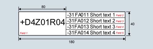
Y33
Four-line label for system identification, 40 × 180 mm
✓
✓
✓
✓
–
✓
✓
✓
✓
✓
✓
✓
✓
SINAMICS S120 Cabinet Modules
Air-cooled Cabinet Modules
Liquid-cooled Cabinet Modules
Order code
Options
Line Connection Module
Basic Line Module
Smart Line Module
Active Line Module with Active Interface Module
Motor Module Booksize (Cabinet Kit)
Motor Module Booksize (Base Cabinet)
Motor Module Chassis
Central Braking Module
Auxiliary Power Supply Module
Basic Line Connection Module
Active Line Connection Module
Motor Module
Heat Exchanger Module
Converter acceptance inspection
F03
Visual acceptance
✓
✓
✓
✓
–
✓
✓
✓
✓
✓
✓
✓
✓
F71
Function test without motor (witnessed by customer)
✓
✓
✓
✓
–
✓
✓
✓
✓
✓
✓
✓
✓
F72
Function test without motor (not witnessed by customer)
✓
✓
✓
✓
–
✓
✓
✓
✓
✓
✓
✓
✓
F74
Function test with test bay motor (not witnessed by customer) 10)
✓
✓
✓
✓
–
✓
✓
–
–
✓
✓
✓
✓
F75
Function test with test bay motor (witnessed by customer) 10)
✓
✓
✓
✓
–
✓
✓
–
–
✓
✓
✓
✓
F76
Insulation test (not witnessed by customer)
✓
✓
✓
✓
–
✓
✓
✓
✓
✓
✓
✓
✓
F77
Insulation test (witnessed by customer)
✓
✓
✓
✓
–
✓
✓
✓
✓
✓
✓
✓
✓
F97
Customer-specific acceptance inspections (on request)
✓
✓
✓
✓
–
✓
✓
✓
✓
✓
✓
✓
✓
✓
Option can be ordered for this Cabinet Module
–
Option cannot be ordered for this Cabinet Module
1) Only in conjunction with option K90 or K95.
2) Option G56 cannot be selected for Active Line Modules in frame sizes FX and GX.
3) For Basic Line Modules for cable lengths < 100 m. Not for a parallel connection of Line Modules to a common Line Connection Module.
4) For rated currents ≤ 800 A.
5) Only with option L43 (for Basic Line Modules) and for rated currents ≤2000 A.
6) For rated currents ≥ 800 A.
7) For rated currents ≥ 2000 A.
8) When Basic Line Modules are connected in parallel with a Line Connection Module, there is only space to fit a braking unit in the right-hand Basic Line Module.
9) Can only be ordered for air-cooled Cabinet Modules. Liquid-cooled Cabinet Modules incorporate additional touch protection as a standard feature.
10) For a function test with test-bay motor, the motor is connected to Motor Modules in chassis format and/or Motor Modules in booksize format in the Base Cabinet.
Option selection matrix
Certain options are mutually exclusive. Options that are not affected are not shown.
✓
Possible combination
–
Combination not possible
Electrical options
G20
G33
G62
K90
K95
G20
–
–
✓
✓
G33
–
–
✓
✓
G62
–
–
✓
✓
K90
✓
✓
✓
–
K95
✓
✓
✓
–
L61/64
L62/65
L61/64
–
L62/65
–
K46
K48
K50
K51
K52
K88
L07
L08
L09 1)
L10
L34
L37
K46
–
–
–
–
✓
✓
✓
✓
✓
✓
✓
K48
–
–
–
–
✓
✓
✓
✓
✓
✓
✓
K50
–
–
–
✓
✓
✓
✓
✓
✓
✓
✓
K51
–
–
–
–
✓
✓
✓
✓
✓
✓
✓
K52
–
–
✓
–
✓
✓
✓
✓
✓
✓
✓
K88
✓
✓
✓
✓
✓
✓
✓
✓
✓
✓
✓
L07
✓
✓
✓
✓
✓
✓
–
–
–
–
✓
L08
✓
✓
✓
✓
✓
✓
–
–
–
✓
✓
L09 1)
✓
✓
✓
✓
✓
✓
–
–
–
–
✓
L10
✓
✓
✓
✓
✓
✓
–
–
–
–
✓
L34
✓
✓
✓
✓
✓
✓
–
✓
–
–
✓
L37
✓
✓
✓
✓
✓
✓
✓
✓
✓
✓
✓
1) Option for Booksize Cabinet Kit only.
Electrical options (Line Connection Module)
K76
L13 1)
L25 2)
L41
L46 3)
L47 3)
P10
P11
K76
✓
✓
✓
–
✓
✓
✓
L13 1)
✓
–
✓
–
–
✓
✓
L25 2)
✓
–
✓
✓
✓
✓
✓
L41
✓
✓
✓
✓
✓
–
–
L46 3)
–
–
✓
✓
✓
✓
✓
L47 3)
✓
–
✓
✓
✓
✓
✓
P10
✓
✓
✓
–
✓
✓
–
P11
✓
✓
✓
–
✓
✓
–
1) Option for rated currents of ≤800 A only.
2) Option for rated currents of >800 A only.
3) Option for rated currents of ≥2000 A only.
Mechanical/electrical options
L22
L42
L43
L44
M06
M07
M21
M23
M26
M27
M43
M54
M55
M60
M90
Y11
Y31
Y32
Y33
L22
–
✓
–
✓
✓
✓
✓
✓
✓
✓
✓
✓
✓
✓
✓
✓
✓
✓
L42
–
–
–
✓
✓
✓
✓
✓
✓
✓
✓
–
✓
✓
✓
✓
✓
✓
L43
✓
–
–
✓
✓
✓
✓
✓
✓
✓
✓
–
✓
✓
✓
✓
✓
✓
L44
–
–
–
✓
✓
✓
✓
✓
✓
✓
✓
–
✓
✓
✓
✓
✓
✓
M06
✓
✓
✓
✓
–
✓
✓
✓
✓
✓
✓
✓
✓
✓
✓
✓
✓
✓
M07
✓
✓
✓
✓
–
✓
✓
✓
✓
✓
✓
✓
✓
✓
✓
✓
✓
✓
M21
✓
✓
✓
✓
✓
✓
–
✓
✓
–
–
–
✓
✓
✓
✓
✓
✓
M23
✓
✓
✓
✓
✓
✓
–
✓
✓
–
–
–
– 1)
✓
✓
✓
✓
✓
M26
✓
✓
✓
✓
✓
✓
✓
✓
–
✓
✓
✓
✓
✓
✓
✓
✓
✓
M27
✓
✓
✓
✓
✓
✓
✓
✓
–
✓
✓
✓
✓
✓
✓
✓
✓
✓
M43
✓
✓
✓
✓
✓
✓
–
–
✓
✓
–
–
– 1)
✓
✓
✓
✓
✓
M54
✓
✓
✓
✓
✓
✓
–
–
✓
✓
–
–
– 1)
✓
✓
✓
✓
✓
M55
✓
–
–
–
✓
✓
–
–
✓
✓
–
–
–
✓
✓
✓
✓
✓
M60
✓
✓
✓
✓
✓
✓
✓
– 1)
✓
✓
– 1)
– 1)
–
✓
✓
✓
✓
✓
M90
✓
✓
✓
✓
✓
✓
✓
✓
✓
✓
✓
✓
✓
✓
–
✓
✓
✓
Y11
✓
✓
✓
✓
✓
✓
✓
✓
✓
✓
✓
✓
✓
✓
–
✓
✓
✓
Y31
✓
✓
✓
✓
✓
✓
✓
✓
✓
✓
✓
✓
✓
✓
✓
✓
–
–
Y32
✓
✓
✓
✓
✓
✓
✓
✓
✓
✓
✓
✓
✓
✓
✓
✓
–
–
Y33
✓
✓
✓
✓
✓
✓
✓
✓
✓
✓
✓
✓
✓
✓
✓
✓
–
–
1) Option M60 is already included in M23, M43, and M54 for all Line Modules and Motor Modules in chassis format.
DC busbar system mechanical options (busbars between individual Cabinet Modules)
M80
M81
M82
M83
M84
M85
M86
M87
M80
–
–
✓
–
–
–
–
M81
–
–
–
✓
–
✓
–
M82
–
–
–
–
✓
–
✓
M83
✓
–
–
–
–
–
–
M84
–
✓
–
–
–
✓
–
M85
–
–
✓
–
–
–
✓
M86
–
✓
–
–
✓
–
–
M87
–
–
✓
–
–
✓
–
Documentation
D00
D02
D14
D56
D58
D60
D72
D76
D77
D78
D80
D84
D91
D93
D94
D99
D00
✓
✓
✓
✓
✓
✓
✓
✓
✓
✓
✓
✓
✓
✓
–
D02
✓
✓
✓
✓
✓
✓
✓
✓
✓
✓
✓
✓
✓
✓
–
D14
✓
✓
✓
✓
✓
✓
✓
✓
✓
✓
✓
✓
✓
✓
–
D56
✓
✓
✓
✓
✓
✓
✓
✓
✓
✓
✓
✓
✓
–
–
D58
✓
✓
✓
✓
–
✓
–
–
✓
–
✓
–
–
–
–
D60
✓
✓
✓
✓
–
✓
–
✓
–
–
✓
–
–
–
–
D72
✓
✓
✓
✓
✓
✓
✓
✓
✓
–
✓
✓
✓
✓
–
D76
✓
✓
✓
✓
–
–
✓
✓
✓
–
✓
–
–
–
–
D77
✓
✓
✓
✓
–
✓
✓
✓
✓
✓
✓
✓
✓
✓
–
D78
✓
✓
✓
✓
✓
–
✓
✓
✓
✓
✓
✓
✓
✓
–
D80
✓
✓
✓
✓
–
–
–
–
✓
✓
✓
–
–
–
–
D84
✓
✓
✓
✓
✓
✓
✓
✓
✓
✓
✓
–
✓
✓
–
D91
✓
✓
✓
✓
–
–
✓
–
✓
✓
–
–
–
–
–
D93
✓
✓
✓
✓
–
–
✓
–
✓
✓
–
✓
–
–
–
D94
✓
✓
✓
–
–
–
✓
–
✓
✓
–
✓
–
–
–
D99
–
–
–
–
–
–
–
–
–
–
–
–
–
–
–
Опции
B43, B44, B45
Production flowchartsProduction flowcharts are provided with options B43 to B45. After the order has been clarified, these are emailed as a dual language (English/German) PDF file.
Option
Description
B43
Documentation - Production flowchart: one issue
B44
Documentation - Production flowchart: updated every two weeks
B45
Documentation - Production flowchart: updated every month
D02
Customer documentation (circuit diagram, terminal diagram, layout diagram) in DXF formatOption D02 can be used to order documents such as circuit diagrams, terminal diagrams, layout diagrams, and dimension drawings in DXF format, e.g. for further processing in CAD systems.
D14
Preliminary version of customer documentation in PDF formatIf documents such as circuit diagrams, terminal diagrams, layout diagrams and dimension drawings are required in advance for the purpose of system engineering (integration of drive into higher-level systems, interface definition, installation, building planning, etc.), it is possible to order a draft copy of the documentation when ordering the Cabinet Modules. These documents are then supplied electronically a few working days following receipt of the order. If the order includes options that fall outside the scope of standard delivery, these will not be covered by the documentation due to the obvious time constraints.
Documentation relating to the order is sent to the buyer by email. The recipient's email address must be specified with the order for this purpose. In the email, the recipient will also receive a link (Internet address) for downloading general, non-order-specific documentation such as the Operating Instructions, Equipment Manual and Commissioning Instructions.
D58, D60, D80, D91, D93, D94
Documentation as language packageIf a documentation option is not selected, the relevant documentation is supplied as standard in English/German. When one of the options specified in the table is selected, the standard documentation language will be changed from English / German to the language combination provided by the option.
Order code
Language
D58
English/French
D60
English/Spanish
D80
English/Italian
D91
English/Chinese
D93
English/Portuguese (Brazil)
D94
English/Russian
D00, D56, D72, D76, D77, D78, D84
Documentation in a single languageThe documentation is also available in a single language, for example, to be able to order other language combinations.
If a further language is required for standard documentation in English/German, the option D74 (documentation in English/German) must also be ordered in addition to that language.
Order code
Language
D00
German
D56
Russian
D72
Italian
D76
English
D77
French
D78
Spanish
D84
Chinese
D99
Without operating instructionsThe Cabinet Modules or Booksize Cabinet Kit are shipped without a documentation CD.
F03, F71, F72, F74, F75, F76, F77, F97
Converter acceptance inspectionsOrder code
Description
F03
Visual acceptance
The inspection includes the following:
- Check of degree of protection
- Check of equipment (components)
- Check of equipment identifiers
- Check of clearance and creepage distances
- Check of cables
- Check of customer documentation
- Submission of the acceptance report
All the above checks are performed with the equipment in a no-voltage condition.
F71 (witnessed by customer)
F72 (not witnessed by customer)Function test without motor
After the visual acceptance with the converter switched off, the converter is connected to rated voltage. No current at the converter output end.
The inspection includes the following:
- Visual acceptance as described for option F03
- Check of power supply
- Check of protective and monitoring devices (simulation)
- Check of fans
- Pre-charging test
- Function test without connected motor
- Submission of the acceptance report
F74 (not witnessed by customer)
F75 (witnessed by customer)Function test with test bay motor under no-load conditions
After the visual acceptance with the converter switched off, the converter is connected to rated voltage. A small current flows at the converter output end in order to operate the test bay motor under no-load conditions.
The inspection includes the following:
- Visual acceptance as described for option F03
- Check of power supply
- Check of protective and monitoring devices (simulation)
- Check of fans
- Function test with test bay motor under no-load conditions
- Submission of the acceptance report
F76 (not witnessed by customer)
F77 (witnessed by customer)Insulation test of the equipment
The inspection includes the following:
- High-voltage test
- Measurement of the insulation resistance
- Submission of the acceptance report
F97
Customer-specific acceptance inspections (on request)
If acceptance inspections that are not covered by the options F03, F71/F72, F74/F75 or F76/F77 are required, then customer-specific acceptance inspections/supplementary tests can be ordered using order code F97 on request and following technical clarification.
G20
CBC10 Communication BoardThe CBC10 Communication Board is used to interface the CU320‑2 Control Unit and thus the SINAMICS S120 Cabinet Modules to the CAN (Controller Area Network) protocol. The associated driver software fulfills the standards of the following CANopen specification of the CiA organization (CAN in Automation):
- Communication profiles according to DS 301
- Drive profile in accordance with DSP 402 (in this case Profile Velocity Mode)
- EDS (Electronic Data Sheet) in accordance with DSP 306
- Operational state signaling according to DSP 305
The CBC10 Communication Board plugs into the option slot on the CU320‑2 Control Unit. The CAN interface on the CBC10 has 2 SUB‑D connections for input and output.
The CBC10 Communication Board can only be ordered in conjunction with a CU320‑2 Control Unit (option K90 or K95). A combination with options G33 and G62 is not possible.
Description of the CBC10 Communication Board → Chassis format units → System components → Supplementary system components.
G33
CBE20 Communication BoardThe CBE20 Communication Board can be used to connect the SINAMICS S120 Cabinet Modules to a PROFINET‑IO or EtherNet/IP network via a CU320‑2 Control Unit. The CBE20 Communication Board plugs into the option slot on the CU320‑2 Control Unit.
The CBE20 Communication Board can only be ordered as option G33 in conjunction with a CU320‑2 Control Unit (option K90 or K95) and is supplied in an accessories pack for possible configuration. A combination with options G20 and G62 is not possible.
Note:
Only one communication interface can be used in isochronous operation when operating the Communication Board CBE20 in a Control Unit CU320‑2.
- CU320-2 DP: Either the DP interface of the Control Unit or the PN interfaces of the CBE20
- CU320-2 PN: Either the internal PN interfaces or the external PN interfaces of the CBE20
Description of the CBE20 Communication Board → Chassis format units → System components → Supplementary system components.
G51 to G54
TM150 temperature sensor evaluation unitOptions G51 to G54 can be used to order between one and four TM150 Terminal Modules for sensing and evaluating several temperature sensors.
Order code
Option
G51
1 x TM150 temperature sensor evaluation unit
G52
2 x TM150 temperature sensor evaluation units
G53
3 x TM150 temperature sensor evaluation units
G54
4 x TM150 temperature sensor evaluation units
The TM150 Terminal Module is a DRIVE‑CLiQ component for temperature evaluation. The temperature is measured in a temperature range from -99 °C to +250 °C for the following temperature sensors:
- Pt100 (with monitoring for wire breaks and short-circuits)
- Pt1000 (with monitoring for wire breaks and short-circuits)
- KTY84 (with monitoring for wire breaks and short-circuits)
- PTC (with monitoring for short-circuits)
- Bimetallic NC contact (without monitoring)
For the temperature sensor inputs, the evaluation can be parameterized for 1x2-wire, 2x2-wire, 3-wire or 4-wire for each terminal block. There is no electrical isolation in the TM150.
A maximum of 12 temperature sensors can be connected to the TM150 Terminal Module.
Description of the TM150 Terminal Module → SINAMICS S120 chassis format units → System components → Supplementary system components.
G56
Contactor monitoringThe option is used for monitoring the pre-charging and bypass contactors of the Line Modules, mainly for infeeds connected in parallel.
Note:
Option G56 cannot be selected for Active Line Modules in frame sizes FX and GX.
G60
TM31 Terminal ModuleThe TM31 Terminal Module is used to expand the customer terminal.
The following additional interfaces are available:
- 8 digital inputs
- 4 bidirectional digital inputs/outputs
- 2 relay outputs with changeover contact
- 2 analog inputs
- 2 analog outputs
- 1 temperature sensor input (KTY84‑130/PTC)
- 2 DRIVE-CLiQ sockets
- 1 connection for the electronics power supply via the 24 V DC supply connector
- 1 PE connection
To simplify configuration and commissioning of the drive, the optional TM31 Terminal Module is already preset with various factory settings, which can then be selected when commissioning the system.
Description of the TM31 Terminal Module → SINAMICS S120 chassis format units → System components → Supplementary system components.
For additional information, please refer to the SINAMICS Low Voltage Engineering Manual.
G61
Additional TM31 Terminal ModuleWith option G61, the number of digital inputs/outputs, as well as the number of analog inputs/outputs in the drive system can be expanded using a second TM31 Terminal Module (in addition to the TM31 Terminal Module that can be selected using option G60).
Note:
Option G61 requires option G60.
G62
TB30 Terminal BoardThe TB30 Terminal Board provides a way of adding digital inputs/digital outputs and analog inputs/analog outputs to the Control Unit. The TB30 Terminal Board plugs into the option slot on the Control Unit.
The following are located on the TB30 Terminal Board:
- Power supply for digital inputs/digital outputs
- 4 digital inputs
- 4 digital outputs
- 2 analog inputs
- 2 analog outputs
The TB30 Terminal Board can only be ordered in conjunction with a CU320‑2 Control Unit (option K90 or K95). A combination with options G20 and G33 is not possible.
Description of the TB30 Terminal Board → SINAMICS S120 chassis format units → System components → Supplementary system components.
K01 to K05
Safety license for 1 to 5 axesThe Safety Integrated basic functions do not require a license. In the case of Safety Integrated Extended Functions, however, a license is required for each axis equipped with safety functions. It is irrelevant which safety functions are used and how many.
Option K01 includes the license for 1 axis, K02 for 2 axes, etc. up to option K05 for 5 axes.
The required licenses can be optionally ordered with the CompactFlash card.
Subsequent licensing is possible online via the WEB License Manager by generating a license key:
http://www.siemens.com/automation/license
K08
AOP30 Advanced Operator Panel installed in the cabinet doorThe AOP30 Advanced Operator Panel is an optional input/output device for the Cabinet Modules. If, for the Cabinet Module or the Booksize Cabinet Kit, an autonomous closed-control (option K90 or K95) is selected, this module can be assigned to its own operator panel with option K08.
The AOP30 Advanced Operator Panel is installed in the cabinet door of each Cabinet Module.
Description of the AOP30 → Chassis format units → System components → Supplementary system components.
K46
SMC10 Sensor Module Cabinet-MountedThe SMC10 Sensor Module Cabinet-Mounted can be used to simultaneously sense the speed and the rotor position angle. The signals received from the resolver are converted here and made available to the closed-loop controller via the DRIVE‑CLiQ interface for evaluation purposes.
The following encoder signals can be evaluated:
- 2-pole resolver
- Multi-pole resolver
The motor temperature can also be measured using KTY84‑130 or PTC thermistors.
Description of the SMC10 Sensor Module Cabinet-Mounted → Chassis format units → System components → Supplementary system components.
K48
SMC20 Sensor Module Cabinet-MountedThe SMC20 Sensor Module Cabinet-Mounted can be used to simultaneously sense the speed and position. The signals received from the incremental encoder are converted here and made available to the closed-loop controller via the DRIVE‑CLiQ interface for evaluation purposes.
The following encoder signals can be evaluated:
- Incremental encoder sin/cos 1 Vpp
- Absolute encoder EnDat 2.1
- SSI encoder with incremental signals sin/cos 1 Vpp
The motor temperature can also be measured using KTY84‑130 or PTC thermistors.
Description of the SMC20 Sensor Module → Chassis format units → System components → Supplementary system components.
K50
SMC30 Sensor Module Cabinet-MountedThe SMC30 Sensor Module Cabinet-Mounted can be used to evaluate the encoders of motors without a DRIVE‑CLiQ interface. External encoders can also be connected via the SMC30.
The following encoder signals can be evaluated:
- Incremental encoders TTL/HTL with and without open-circuit detection (open-circuit detection is only available with bipolar signals)
- SSI encoders with TTL/HTL incremental signals
- SSI encoders without incremental signals
The motor temperature can also be measured using KTY84‑130 or PTC thermistors.
Description of the SMC30 Sensor Module → Chassis format units → System components → Supplementary system components.
K51
VSM10 Voltage Sensing ModuleThe VSM10 Voltage Sensing Module is used to measure the voltage characteristic on the motor side, so that the following function can be implemented:
- Operation of a permanent-magnet synchronous motor without encoder with the requirement to be able to connect to a motor that is already running (flying restart function)
- Quick flying restart of large induction motors: The voltage sensing function eliminates the delay incurred by demagnetization of the motor.
Description of the VSM10 Voltage Sensing Module → Chassis format units → System components → Supplementary system components.
K52
Second SMC30 Sensor Module Cabinet-MountedWith option K50, the cabinet unit contains an SMC30 Sensor Module Cabinet-Mounted. An additional SMC30 (option K52) enables reliable actual-value acquisition when Safety Integrated extended functions are used (requires a license: options K01 to K05).
Detailed and comprehensive instructions and information for the Safety Integrated functions can be found in the associated Function Manual.
K70
Fan power supplyWith option K70, the line voltage supply for the 400 V 3 AC auxiliary power supply system is tapped downstream of the circuit breaker and protected by a motor starter protector.
The voltages 230 V 1 AC and 24 V DC of the auxiliary power supply system are supplied externally on the plant side.
K73
SITOP power supply 24 V DCThe 24 V DC supply for standard Booksize Cabinet Kits is tapped from the auxiliary power supply.
With option K73, the 24 V DC supply is provided by a dedicated SITOP power supply unit.
K76
Auxiliary voltage generation in the Line Connection ModuleCabinet Modules require an auxiliary energy supply to function properly. This current demand must be included in the configuration and supplied from an external source. If an external supply is not possible, the required auxiliary voltages can be supplied by means of an Auxiliary Power Supply Module.
Alternatively, option K76 can be selected. This provides for generation of auxiliary voltages in the Line Connection Module. This is particularly advisable for smaller device configurations.
With option K76, the following auxiliary voltages are provided:
Air-cooled Cabinet Modules
Liquid-cooled Cabinet Modules
380 ... 480 V or 500 ... 690 V 2 AC
Possible tap for the following Line Connection Modules:
- Line Connection Module with rated current up to 800 A: 35 A
- Line Connection Module with rated current of 1000 to 1600 A: 50 A
- Line Connection Module 6SL3700‑0LE42‑0AA3: 50 A
- Line Connection Module with rated current of 2000 to 3200 A: 80 A
–
230 V 1 AC
Possible tap for the Line Connection Modules:
- <800 A: approx. 4 A
- > 800 A: approx. 6 A
Possible tap for Basic Line Connection Modules / Active Line Connection Modules
- 4 ... 10 A
24 V DC
Possible tap for the Line Connection Modules:
- <800 A: approx. 20 A
- > 800 A: approx. 40 A
Possible tap for Basic Line Connection Modules / Active Line Connection Modules
- 5 ... 20 A
The supply for the auxiliary power supply system is connected at the auxiliary voltage module of the Line Connection Module.
K82
Terminal Module for controlling the Safe Torque Off and Safe Stop 1 safety functionsThe terminal module controls the Safety Integrated Basic Functions Safe Torque Off (STO) and Safe Stop 1 (SS1) (time-controlled) over a wide voltage range from 24 V to 240 V DC/AC (terminology as defined in IEC 61800‑5‑2).
The integrated safety functions, starting from the Safety Integrated (SI) input terminals of the components (Control Unit and Motor Module), satisfy the requirements of EN 61800‑5‑2, EN 60204‑1, DIN EN ISO 13849‑1 Category 3 for Performance Level (PL) d and IEC 61508 SIL 2.
With option K82, the requirements specified in EN 61800‑5‑2, EN 60204‑1, DIN EN ISO 13849‑1 Category 3 for Performance Level (PL) d and IEC 61508 SIL 2 are fulfilled.
The Safety Integrated functions using option K82 are only available in conjunction with certified components and software versions.
The Safety Integrated functions of SINAMICS are generally certified by independent institutes. An up-to-date list of certified components is available on request from your local Siemens office.
K87
TM54F Terminal ModuleThe TM54F Terminal Module is a terminal expansion module with safe digital inputs and outputs to control the Safety Integrated functions.
The TM54F is directly connected to a Control Unit via DRIVE‑CLiQ. Each Control Unit can be assigned precisely to one TM54F.
Note:
It is not permissible to connect Motor Modules or Line Modules to a TM54F.The TM54F provides 4 fail-safe digital outputs and 10 fail-safe digital inputs. A fail-safe digital output consists of one 24 V DC switching output, one output switching to ground and one digital input to check the switching state. A fail-safe digital input consists of two digital inputs.
Description of the TM54F Terminal Module → SINAMICS S120 chassis format units → System components → Supplementary system components.
K88
SBA Safe Brake Adapter, 230 V ACThe Safe Brake Control (SBC) is a safety function, which is used in safety-relevant applications, for example in presses or rolling mills. In the no-current state, the brake acts on the drive motor using spring force. The brake is released when current flows in it (low active).
The Safe Brake Adapter is already installed in the cabinet unit in the factory. An infeed is connected to terminal -X12 on the Safe Brake Adapter for the power supply. For control, a connection is established between the Safe Brake Adapter and the Control Interface Module in the factory using a cable harness.
On the plant side, to control the brake, a connection must be established between terminal ‑X14 on the Safe Brake Adapter and the brake.
Description of the SBA Safe Brake Adapter → SINAMICS S120 chassis format units → System components → Supplementary system components.
K90
CU320‑2 DP Control Unit (PROFIBUS)Option K90 assigns a CU320-2 DP Control Unit incl. CompactFlash card to the Line Modules and Motor Modules. This unit handles the communication and open-loop/closed-loop control functions. DRIVE‑CLiQ is used to establish a connection to the various modules and where required, to additional I/O modules. A PROFIBUS interface is available as standard for the higher-level communication.
The computational performance required from the Control Unit CU320‑2 DP increases with the number of connected Motor Modules and system components – as well as the dynamic performance demanded.
Without performance expansion, it is generally possible to operate two Motor Modules with one Line Module.
The full computational performance of the CU320‑2 DP is only available on systems with performance expansion (option K94).
Description of the CU320-2 DP Control Unit → SINAMICS S120 chassis format units → System components → Control Units.
K94
Performance expansion for CU320‑2 Control UnitWith option K94, the CU320-2 Control Unit (option K90 or K95) is supplied with a CompactFlash card with performance expansion. This therefore provides the full computational performance of the CU320‑2 Control Unit.
In addition to the firmware, the CompactFlash card also contains licensing codes that are required to enable firmware options, for example, the performance expansion and the Safety Integrated Extended Functions.
K95
CU320‑2 PN Control Unit (PROFINET)Option K95 assigns a CU320‑2 PN Control Unit, incl. CompactFlash card, to the Line Modules and Motor Modules. This unit handles the communication and open-loop/closed-loop control functions. DRIVE‑CLiQ is used to establish a connection to the various modules and where required, to additional I/O modules. A PROFINET interface is available for the higher-level communication.
The computational performance required from the CU320‑2 PN Control Unit increases with the number of connected Motor Modules and system components – as well as the dynamic performance demanded.
Without performance expansion, it is generally possible to operate two Motor Modules with one Line Module.
The full computational performance of the CU320‑2 PN is only available on systems with performance expansion (option K94).
Description of the CU320-2 DP Control Unit → SINAMICS S120 chassis format units → System components → Control Units.
L00
Use in the first environment according to EN 61800‑3, Category C2 (TN/TT supply systems with grounded neutral point)With option L00, the Line Modules have a line filter as well as additional measures installed in the factory; this means that the Cabinet Modules can also comply with the limit values for use in the first environment (Category C2) according to EN 61800-3.
Notes on the measures to be implemented by the customer are provided in the SINAMICS Low Voltage Engineering Manual.
In order to achieve the full filter effect, the optional line filter must always be used in conjunction with a line reactor.
Note:
Option L00 is not available for Line Modules in a parallel connection.
L07
dv/dt filter compact plus Voltage Peak Limiterdv/dt filters compact plus VPL (Voltage Peak Limiter) limit the voltage rate-of-rise dv/dt to values of < 1600 V/μs and the typical voltage peaks to the following values in accordance with the limit value curve A according to IEC 60034‑25: 2007:
- < 1150 V at Uline < 575 V
- <1400 V at 660 V < Uline < 690 V
The dv/dt filter compact plus VPL functionally consists of two components that are supplied as a compact mechanical unit, the dv/dt reactor and the voltage limiting network (VPL), which limits voltage peaks and feeds back the energy to the DC link.
It is so compact that it can be completely integrated into the cabinet, even for high power ratings. An additional cabinet is not required.
By using a dv/dt filter compact plus VPL, standard motors with standard insulation and without insulated bearings can be used with supply voltages up to 690 V in converter operation.
The power losses stated in system component section System components → Motor-side components → dv/dt filters compact plus VPL can be used to determine the total losses for engineering purposes.
dv/dt filters compact plus VPL are designed for the following maximum motor cable lengths:
- Shielded cables 100 m (e.g. Protodur NYCWY)
- Unshielded cables 150 m (e.g. Protodur NYY)
For longer cable lengths (> 100 m shielded, >150 m unshielded), the dv/dt filter plus VPL (option L10) should be used.
Notice:
- Operation with output frequencies <10 Hz is permissible for max. 5 min.
- The maximum permissible output frequency is 150 Hz.
When using dv/dt filters, restrictions regarding permissible pulse frequencies must be observed.
Please also note the relevant information provided in the SINAMICS Low Voltage Engineering Manual.
Note:
Option L07 cannot be combined with the following options:
- L08 (motor reactor)
- L10 (dv/dt filter plus VPL)
L08
Motor reactorMotor reactors reduce the voltage load on the motor windings by reducing the voltage gradients at the motor terminals that occur during converter operation. At the same time, the capacitive charge/discharge currents that place an additional load at the Motor Module output when long motor cables are used are reduced.
Suitably dimensioned motor reactors or a series connection of several motor reactors make it possible to connect larger capacitances and thus allow the use of longer motor cables.
In the case of multi-motor drives, the use of motor reactors is recommended as a general principle.
The motor reactor is accommodated in the Cabinet Module. An additional 600-mm-wide cabinet located to the right of the Motor Module is only required for the chassis format in frame sizes HX and JX.
The power losses stated in the section System components > Motor-side components > Motor reactors can be used to determine the total losses for engineering purposes.
Note:
The terminal lugs of the reactors are not nickel-plated.
For Motor Modules in chassis format, the maximum cable lengths when using motor reactors are 300 m (shielded) or 450 m (unshielded).
For Motor Modules in Booksize Cabinet Kit format, by using motor reactors (option L08) the maximum motor cable lengths, specified in the following table, can be reached:
Booksize Cabinet Kit
Rated output current of Motor Module
Maximum motor cable length
when using motor reactors for Booksize Cabinet Kits
Shielded cable
Unshielded cable
Without reactor
With one reactor (option L08)
With two reactors in series (option L09)
Without reactor
With one reactor (option L08)
With two reactors in series (option L09)
6SL3720-...
A
m
m
m
m
m
m
1TE21-0AB3
9
50
135
–
75
200
–
1TE21-8AB3
18
70
160
320
100
240
480
1TE23-0AB3
30
100
190
375
150
280
560
1TE24-5AB3
45
100
200
400
150
300
600
1TE26-0AB3
60
100
200
400
150
300
600
1TE28-5AB3
85
100
200
400
150
300
600
1TE31-3AB3
132
100
200
400
150
300
600
L09
Two motor reactors in seriesWith option L09 for Booksize Cabinet Kits, two motor reactors are used in series that can be located within the standard width of the Cabinet Kit.
The maximum permissible motor cable lengths when using option L09 are specified in the table under option L08.
Note:
The terminal lugs of the reactors are not nickel-plated.
L10
dv/dt filter plus Voltage Peak LimiterA dv/dt filter plus VPL (Voltage Peak Limiter) limits the voltage rate-of-rise dv/dt to values < 500 V/μs and the typical voltage peaks to the following values in accordance with the limit value curve specified in IEC/TS 60034‑17: 2006:
- < 1000 V at Uline < 575 V
- <1250 V at 660 V < Uline < 690 V
The dv/dt filter plus VPL functionally consists of two components, the dv/dt reactor and the voltage limiting network (VPL), which limits voltage peaks and feeds the energy back to the DC link.
Option L10 is installed in an additional cabinet with a width of 600 mm that is located on the right-hand side of the Motor Module.
By using a dv/dt filter plus VPL, standard motors with standard insulation and without insulated bearings can be used with supply voltages up to 690 V in converter operation.
dv/dt filters plus VPL are designed for the following maximum motor cable lengths:
- Shielded cable (e.g. Protodur NYCWY)
- Motor Modules, frame sizes FX to HX: 300 m
- Motor Modules, frame size JX: 150 m
- Unshielded cables (e.g. Protodur NYY)
- Motor Modules, frame sizes FX to HX: 450 m
- Motor Modules, frame size JX: 225 m
For cable lengths < 100 m shielded or < 150 m unshielded, the dv/dt filter compact plus VPL (option L07) can be used advantageously.
The power losses stated in the section System components > Motor-side components > dv/dt filters plus VPL can be used to determine the total losses for engineering purposes.
Notice:
- Operation with output frequencies <10 Hz is permissible for max. 5 min.
- The maximum permissible output frequency is 150 Hz.
When using dv/dt filters, restrictions regarding permissible pulse frequencies must be observed.
Please also note the relevant information provided in the SINAMICS Low Voltage Engineering Manual.Note:
Parts of option L10 do not have nickel-plated copper busbars.
Option L10 cannot be combined with the following options:- L07 (dv/dt filter compact plus VPL)
- L08 (motor reactor)
L13
Main contactor (for supply currents ≤ 800 A)Line Connection Modules for current ratings up to 800 A feature only a manually operated fuse switch disconnector as standard. Option L13 is needed if a switching element is also required for disconnecting the cabinet from the supply (needed for EMERGENCY OFF). The contactor is controlled by the closed-loop control in this case. Option L13 can be ordered for Line Connection Modules together with Basic Line Modules (option L43). With Smart Line Modules and Active Line Modules, the contactor is included as standard.
L21
Surge suppressionIn ungrounded IT systems, the line voltage is not permanently connected to the ground potential because of the missing ground connection of the supply network. Therefore, when a ground fault occurs during operation, a voltage against ground increased by a factor of 2 can occur. For this reason, it is recommended that a surge suppression against ground be installed for operation on IT systems. The surge suppression option includes the installation of line-side surge arresters and upstream fuses for each system phase. The signaling contacts for monitoring the surge arresters are connected in series and connected to a customer interface.
Note:
Option L21 does not include the components required to install an insulation monitor for the IT system. An insulation monitor should always be ordered separately as option L87 when the supplying IT system is not monitored at another position (e.g. at the transformer outgoing feeder). Only one insulation monitor can ever be used within the same electrically-connected network.
Option L21 also does not include removal in the factory of the metal bracket that makes the connection to ground of the radio interference suppression filter installed as standard. The metal bracket should therefore be removed during the installation or commissioning of the converter if the device is to be operated on an ungrounded IT system.L22
Delivery scope without line reactorThe air-cooled Basic Line Modules and Smart Line Modules as well as the liquid-cooled Basic Line Connection Modules are supplied with line reactors as standard; the reason for this is that frequently in practice the line configuration at the connection point of the drive line-up and/or the line supply short-circuit power is not known.
If the supply is connected through a separate transformer or if the line has a suitably low short-circuit power or if the standard integrated line reactor does not need to be supplied for other reasons, then this can be indicated by selecting option L22.
In the case of air-cooled Cabinet Modules, option L22 can be selected for Line Connection Modules (rated current < 2000 A) in conjunction with Basic Line Modules (option L43) and for Smart Line Modules. In the case of liquid-cooled Cabinet Modules, option L22 can be selected for Basic Line Connection Modules.
For Basic Line Modules and Basic Line Connection Modules connected in parallel, a line reactor should always be used, i.e. option L22 cannot be selected.
The power losses of each line reactor stated in section System components → Line-side components → Line reactors can be deducted from the total power loss for engineering purposes.
For additional information, please refer to the SINAMICS Low Voltage Engineering Manual.
L25
Withdrawable circuit breakerLine Connection Modules (air-cooled), Active Line Connection Modules and Basic Line Connection Modules (liquid-cooled) with an input current of > 800 A are equipped with fixed-mounted circuit breakers as standard. Where the customer requires a visible isolating distance, a withdrawable circuit breaker can be ordered as an option.
L34
Output-side circuit breakerOption L34 can be used to disconnect the motor terminals from the Motor Module Chassis.
A rotating permanent-magnet synchronous motor generates a voltage at its motor terminals proportional to the speed. The motor terminal voltage is also available at the inverter output terminals as well as at the DC link and the components connected to it.
Option L34 is available for disconnection in the case of a fault or if maintenance work is to be carried out.
Option L34 is completely prewired and is accommodated in an additional cabinet, which is arranged at the right-hand side of the Motor Module (400 mm wide for frame sizes FX/GX, 600 mm wide for frame sizes HX/JX). It is controlled using a TM31 Terminal Module, which is included with this option. This means that the output switch is automatically controlled via the Motor Module.
Option L34 cannot be combined with the following options:
- L07 (dv/dt filter compact plus VPL)
- L10 (dv/dt filter plus VPL)
L37
DC interface incl. pre-charging circuit of the relevant DC link capacitanceIf, for reasons relating to the process or availability, the Motor Module needs to be disconnected from the common DC link for an entire drive line-up or connected to it during operation, a manually operated isolating distance can be ordered as an option. With chassis format power units, this takes the form of switch disconnectors, and with Booksize Cabinet Kits, a contactor combination.
Option L37 is installed on the busbar between the Motor Module and the main DC busbar. To ensure that the module can be connected to a pre-charged DC link, the option also includes a pre-charging circuit for the DC link capacitors of the relevant Motor Module.
The switching operation is performed externally. The operating levers can be locked using a padlock (padlock not included in scope of delivery). The degree of protection of the cabinets is not influenced.
The air guidance contains option L37 and also option M60 (additional touch protection).
Options L61/L62 and L64/L65 (braking units) cannot be ordered together with option L37 for space reasons.
L40
Line filter monitoringWith option L40, the filter in the Active Interface Module is monitored for effectiveness against harmonic effects on the system. The capacitance of the filter capacitors of the integrated filter is continuously calculated and compared with the installed nominal capacitance by measuring the current and voltage in the Active Interface Module. If the calculated capacity deviates by more than the set tolerance, an alarm is triggered.
L41
Current transformer upstream of main circuit breakerIf additional current transformers are required for measuring or monitoring purposes, these can be ordered for (air-cooled) Line Connection Modules or (liquid-cooled) Active Line Connection Modules and Basic Line Connection Modules with option L41. The current transformers are installed upstream of the main circuit breaker in all three infeed phases.
The transformers have an accuracy class of 1.0. The secondary current is maximum 1 A.
The transformer measuring connections are routed to the terminal block in the Line Connection Module.
Note:
These current transformers are already included in options P10 and P11 (measuring instrument for the display of line values).
L42
Line Connection Module for Active Line ModulesOrder code L42 is specified in the order to indicate that the Line Connection Module will be connected to an Active Line Module. The Line Connection Module is then adapted accordingly (pre-charging circuit, connection busbars, etc.). See also the information for the Line Connection Modules and the overview of options.
L43
Line Connection Module for Basic Line ModulesOrder code L43 is specified in the order to indicate that the Line Connection Module will be connected to a Basic Line Module. The Line Connection Module is then adapted accordingly (line reactors, pre-charging circuit, connection busbars, etc.). See also the information for the Line Connection Modules and the overview of options.
L44
Line Connection Module for Smart Line ModulesOrder code L44 is specified in the order to indicate that the Line Connection Module will be connected to a Smart Line Module. The Line Connection Module is then adapted accordingly (pre-charging circuit, connection busbars, etc.). See also the assignment table for the Line Connection Modules and the overview of options.
L45
EMERGENCY OFF pushbutton, installed in the cabinet doorThe EMERGENCY OFF pushbutton with protective collar is installed in the cabinet door of the Line Connection Module and its contacts are connected to a terminal block. From here, the EMERGENCY OFF pushbutton can be integrated into the plant-side EMERGENCY OFF chain.
L46
Grounding switch upstream of main circuit breakerThe grounding switch is upstream of the circuit breaker in the Line Connection Module and short-circuits the incoming supply system to ground. The grounding switch is manually engaged using a rotary operating mechanism to ensure isolation from the line supply when maintenance is being carried out. Measures must be taken at the plant to ensure that the grounding switch cannot be engaged when voltage is applied.
It is also essential to ensure that the supply system cannot be connected when the grounding switch is engaged.
The signals required for mutual interlocking are available on the terminal block.
L47
Grounding switch downstream of main circuit breakerThe grounding switch is installed downstream of the circuit breaker in the Line Connection Module and short-circuits the incoming supply system to ground downstream of the main circuit breaker. The grounding switch is manually engaged using a rotary operating mechanism to ensure isolation from the line supply when maintenance work is being carried out on the converter.
In this case, the grounding switch and the main circuit breaker for the Line Connection Module are interlocked with each other, which ensures that the grounding switch cannot be closed when the main circuit breaker is closed.
If the grounding switch is engaged, it is interconnected to ensure that the main circuit breaker cannot be closed.
L50
Cabinet lighting with service socketWith option L50, cabinet lighting is included with an additional service socket for a SCHUKO connector (connector type F) according to CEE 7/4. The power supply for the cabinet lighting and the service socket is external and must be fuse-protected for max. 10 A.
The cabinet lighting consists of an LED hand lamp with On/Off switch and with magnetic fasteners with an approx. 3 m long connecting cable. The lamp is factory-positioned in the cabinet door at a defined marking, and the connecting cable is wound on the associated mount.
L55
Cabinet anti-condensation heatingThe anti-condensation heating is recommended at low ambient temperatures and high levels of humidity to prevent condensation. Depending on the cabinet width, a 100 W cabinet heater is installed for each Cabinet Module.
1 heating element for cabinet width up to 600 mm, 2 heating elements for cabinet width over 800 mm.
The power supply for the anti-condensation heating (110 V to 230 V AC, at terminal block ‑X240) must be provided externally and fused with max. 16 A.
L61, L62, L64, L65
Braking unitsBraking units may be required for drives in which motors might operate in generator mode, but have no facility for feeding energy back into the supply system.
The braking unit comprises two components:
- A Braking Module that can be installed in the air discharge of the chassis format power units
- A braking resistor to be mounted externally (degree of protection IP20).
The braking unit functions as an autonomous unit, and does not require an external power supply. During the braking process, the kinetic energy is converted into heat in the externally mounted braking resistor.
A max. cable length of 100 m is permissible between the Braking Module and the braking resistor. This allows the braking resistor to be mounted externally so that heat losses can be dissipated outside the converter enclosure. The braking resistor is directly connected to the Braking Module.
For SINAMICS S120 Cabinet Modules the following braking modules are available, depending on the frame size:
Option
Can be used with frame sizes
Braking Module
Rated power PDB
Braking power P20
Peak power P15
kW
kW
kW
380 ... 480 V 3 AC, 660 ... 690 V 3 AC
L61
FX
25
100
125
L62
GX, HX, JX
50
200
250
500 ... 600 V 3 AC
L64
FX
25
100
125
L65
GX, HX, JX
50
200
250
PDB: Rated power (continuous braking power)
P20: 20 s power referred to a braking interval of 90 s
P15: 15 s power referred to a braking interval of 90 s
If the braking units listed here do not provide adequate braking power, up to four braking units on a DC link busbar may be connected in parallel. Braking power can be shared among several Modules. In this case, a Braking Module is assigned to each braking resistor.
Note:
It is only possible to use a Braking Module, if a DC interface (option L37) has not been selected for the Motor Module.
When engineering the system, it should be ensured that the module in which the Braking Module is installed is switched on during braking so that the Braking Module is properly cooled. Failure to follow this instruction means that the Braking Module could overheat and shut down, the drive will no longer be able to operate in braking mode. In this case, the Braking Modules should preferably be located in the Line Modules.

Load diagram for Braking Modules and braking resistors
Additional notes about possible duty cycles of the braking resistors and other engineering notes are included in the SINAMICS Low Voltage Engineering Manual.
L87
Insulation monitoringAn insulation monitor must be used if the converter is connected to an ungrounded line supply. The device monitors the entire galvanically coupled circuit for insulation faults.
An alarm is output in the event of a fault.
Notice:
Only one insulation monitor can be used in each galvanically coupled network.
As there are different response strategies when a ground fault occurs in an ungrounded system, output relays of the insulation monitor are provided for integration in a plant-side control. It is also possible to integrate the outputs into the Cabinet Modules monitoring system on the plant side.
M06
Base 100 mm high, RAL 7022The additional cabinet base allows larger bending radii for cables (cable inlet from below) and enables them to be routed within the cabinet base.
The cabinet base is supplied in RAL 7022 as standard. A special paint finish is not available for the base. It is delivered completely assembled with the cabinet. The height of the operator panel changes accordingly.
M07
Cable marshaling space 200 mm high, RAL 7035The cable marshaling space is made of strong sheet steel and allows cables to be connected more flexibly (entry from below). It also allows routing of cables within the marshaling compartment. It is delivered completely assembled with the cabinet. The height of the operator panel changes accordingly.
Notice:
The cable compartment is painted as standard with RAL 7035. If a special color is requested for the cabinet (option Y09), the cable marshaling space is also painted in this color.
M21
Degree of protection IP21 (for air cooling only)Cabinet version in IP20, but with additional top cover or drip protection cover. This increases the cabinet height by 250 mm. For transport reasons, the top or drip protection covers are delivered separately and must be fitted on site.
Notice:
The top covers or canopies are painted in RAL 7035 as standard. If a special color is requested for the cabinet (option Y09), the roof sections or drip protection cover are also painted in this color.
Degree of protection IP21 is the standard version for liquid-cooled Cabinet Modules.
M23
Degree of protection IP23Cabinet Modules with degree of protection IP23 are supplied with additional plastic ventilation grilles and a filter medium in the air inlet and outlet. The filter medium must be maintained according to the local environmental conditions. The covers provided with option M60 are also included in the scope of supply.
The air-cooled Cabinet Modules are additionally supplied with a roof section. This increases the cabinet height by 400 mm. For transport reasons, the roof sections are delivered separately and must be fitted on site.
Notice:
The roof sections are painted in RAL 7035 as standard. If a special color is requested for the cabinet (option Y09), the roof section is also painted in this color. The molded plastic parts (e.g. ventilation grilles) are in RAL 7035 and cannot be painted.
M26
Side panel mounted at the rightFor side-by-side installation of Cabinet Modules from left to right, cabinets can be ordered ready-prepared at the factory for assembly on-site. If option M26 is ordered, the Cabinet Module is shipped with a side panel fitted on the right.
This side panel is essential for ensuring compliance with IP20 and higher degrees of protection.
M27
Side panel mounted to the leftFor side-by-side installation of Cabinet Modules from right to left, cabinets can be ordered ready-prepared at the factory for assembly on-site. If option M27 is ordered, the Cabinet Module is shipped with a side panel fitted on the left.
This side panel is essential for ensuring compliance with IP20 and higher degrees of protection.
M43
Degree of protection IP43Cabinet Modules with degree of protection IP43 are supplied with additional plastic ventilation grilles and a filter medium in the air inlet and outlet. The filter medium must be maintained according to the local environmental conditions. The covers provided with option M60 are also included in the scope of supply.
The air-cooled Cabinet Modules are additionally supplied with a roof section. This increases the cabinet height by 400 mm. For transport reasons, the roof sections are delivered separately and must be fitted on site.
Notice:
The roof sections are painted in RAL 7035 as standard. If a special color is requested for the cabinet (option Y09), the roof section is also painted in this color. The molded plastic parts (e.g. ventilation grilles) are in RAL 7035 and cannot be painted.
M51
Motor connection wired to customer terminalOption M51 is a meaningful add-on to option M77 (version without component support plates or additional control components).
With option M51, the connection of the motor cable is wired to a customer terminal ‑X1 and thus makes the process of connecting motor cables easier.
Without option M51, the motor cable is connected directly to the Motor Module. In systems with one motor reactor or two series-connected motor reactors (option L08/L09), the motor cables are connected directly to the motor reactor.
M54
Degree of protection IP54 (for air cooling only)Cabinet Modules with degree of protection IP54 are supplied with additional roof sections, plastic ventilation grilles, and a filter medium in the air inlet and outlet, which ensures compliance with degree of protection IP54. This increases the cabinet height by 400 mm. For transport reasons, the roof sections are delivered separately and must be fitted on site.
The filters must be maintained according to the local environmental conditions.
Notice:
- The roof sections are painted in RAL 7035 as standard. If a special color is requested for the cabinet (option Y09), the roof section is also painted in this color. The molded plastic parts (e.g. ventilation grilles) are in RAL 7035 and cannot be painted.
- For units with degree of protection IP54, it is important to observe the derating factor for output currents in relation to ambient temperature and installation altitude.
M55
Degree of protection IP55 (for liquid cooling only)Cabinet Modules with degree of protection IP55 are supplied with closed doors and roof sheets (without additional roof section). Water jets from any angle are permitted. Because the cabinets are completely enclosed and there is no exchange of air with the environment, it is not necessary to clean a filter medium.
The derating data are provided in the derating characteristics for the liquid-cooled Cabinet Modules.
Almost all heat losses are dissipated into the cooling liquid.
M56
Reinforced mechanical designThis option includes a strengthened mechanical version of the cabinet and mechanical locking of the cabinet doors. To secure the converter to the floor, a welding frame (5 mm high) is supplied separately. This option is available for all degrees of protection.
Note:
Option M56 cannot be combined with option M70 (EMC shielding busbar).
M59
Closed cabinet doors, air inlet from below through floor openingIf the Cabinet Modules are erected on a false floor or duct which forms part of a forced ventilation system, the modules can be ordered with closed cabinet doors. To ensure an adequate air inlet cross-section, the units are shipped without the standard base plates. In this case, the customer must ensure that no dirt/dust or moisture can enter the Cabinet Module. Cables must not be routed in such a way that they impede the flow of air through the cabinet floor opening. If the area beneath the Cabinet Modules can be accessed, the customer must provide touch protection.
M60
Additional touch protectionThe Cabinet Modules are designed in accordance with BGV A3 as standard. With option M60, additional covers (out of reach) at accessible operator control and switching elements, are provided in the area of the AC and DC busbars and in front of the power unit.
Option M60 is already included in M23, M43, and M54 for the following Cabinet Modules.
- Line Connection Modules
- Basic Line Modules
- Smart Line Modules
- Active Line Modules with Active Interface Modules
- Motor Modules chassis
- Central Braking Modules
- Auxiliary Supply Modules
Liquid-cooled Cabinet Modules incorporate additional touch protection as a standard feature - it does not have to be ordered with option M60.
M70
EMC shield busThe EMC shield bus is used to connect shielded line and motor supply cables. The shields can be applied over a large surface area with the supplied EMC shield clips.
M72
Quick-release couplings for water hoses (for liquid cooling only)With option M72, the ports for connecting the water hoses to the power modules and heat exchangers are fitted with quick-release couplings. The quick-release couplings ensure that no liquid escapes during uncoupling.
The use of quick-release couplings makes disassembly of the power modules and heat exchangers easier.
M77
Version without component support plates and without additional control componentsIf electronic components (Control Unit, Terminal Modules, Sensor Modules) are not used in the Booksize Cabinet Kit, the mechanical component support plates are omitted with option M77, including the customer terminal blocks for connecting motor cables.
The motor cables are then connected directly to the Motor Module in booksize format.
When option L08/L09 is used (motor reactor / 2 motor reactors in series), the motor cables are connected directly to the motor reactor.
The table below provides an overview of possible motor cable connection cross-sections for motor cables connected directly to a Motor Module in booksize format:
Booksize Cabinet Kit
Rated output current of Motor Module
Conductor cross-section
6SL3720-...
A
mm2
1TE21-0AB3
9
1.5 ... 6
1TE21-8AB3
18
1.5 ... 6
1TE23-0AB3
30
1.5 ... 6
1TE24-5AB3
45
6 ... 50
1TE26-0AB3
60
6 ... 50
1TE28-5AB3
85
16 ... 120
1TE31-3AB3
132
25 ... 120
Note:
When combined with option M51, the motor connection is wired to a customer terminal.
M80 to M87
DC busbar systemThe correct DC busbar for the Cabinet Module must be ordered. This is fitted in the upper section of the Cabinet Modules and connects the Line Modules to the Motor Modules.
The busbar is dimensioned according to the load requirements and demand factor associated with operation of the individual drives, and according to the specific Cabinet Module layout. For this reason, the DC busbar is not supplied as standard, but must be ordered as an option.
When selecting busbars, it is important to ensure that the systems of adjacent Cabinet Modules are compatible with one another (refer to the table below and option selection matrix for the Cabinet Modules in question).
Where Cabinet Modules are ordered as a factory-assembled transport unit with option Y11, all busbars in the transport unit must be identical.
Order code
DC busbar system, rated current Irated
Number
Dimensions
Compatible with
A
mm
M80
1170
1
60 × 10
M83
M81
1500
1
80 × 10
M84 and M86
M82
1840
1
100 × 10
M85 and M87
M83
2150
2
60 × 10
M80
M84
2730
2
80 × 10
M81 and M86
M85
3320
2
100 × 10
M82 and M87
M86
3720
3
80 × 10
M81 and M84
M87
4480
3
100 × 10
M82 and M85
The DC busbars are nickel-plated as standard and are available in different designs for a variety of current-carrying capacities. The scope of delivery also includes the jumpers required to link the busbar systems of individual Cabinet Modules.
M88
DC busbar system for line-side Cabinet Modules (for liquid cooling only)Option M88 is required if Motor Modules are to be installed to the left or if up to four Basic Line Connection Modules or Active Line Connection Modules are to be connected for a parallel connection.
For this purpose, DC busbars are built into the upper part on the left hand side in the line-side Cabinet Module of each Active Line Connection Module and Basic Line Connection Module.
The busbars are nickel plated as standard and are selected for different current carrying capacities as for the selected options M80 to M87.
M90
Crane transport assembly (top-mounted)A top-mounted crane transport assembly can be ordered as an option for Cabinet Modules.
Depending on the width of the module, it consists of either transport eyebolts (width ≤800 mm) or transport rails (width >800 mm).
When Cabinet Modules are ordered as factory-assembled transport units (option Y11), they are shipped with transport rails, i.e. option M90 is automatically included in the scope of delivery of option Y11 and does not need to be ordered separately.
M91
Marking of all control cable conductor ends (incl. customer-specific wiring)When this option is selected, all control cables or conductor ends (including all customer-specific options) are labeled throughout the cabinet.
N52
DC link fusesThe Basic Line Modules (air-cooled), Active Line Connection Modules and Basic Line Connection Modules (liquid-cooled) come without DC link fuses as standard.
If fuses are required, they can be ordered with option N52. The fuses are mounted on the connecting rail to the DC busbar in the cabinet rather than in the power unit.
The use of DC link fuses is recommended when Basic Line Modules, Active Line Connection Modules, and Basic Line Connection Modules are connected in parallel.
The Motor Modules contain DC link fuses as standard.
P10
Measuring instrument for line values, mounted in the cabinet doorA measuring instrument with display, installed in the cabinet door of the Line Connection Module, for acquiring measured values of the power supply. In addition to these measured values, additional plant values (such as power and power factor, etc.) are calculated from the measured values using powerful, state-of-the art microprocessors.
Current transformers (option L41) are already included in the scope of delivery.
P11
Measuring instrument for line values with PROFIBUS connection, mounted in the cabinet doorA measuring instrument with display, installed in the cabinet door of the Line Connection Module, for acquiring measured values of the power supply. In addition to these measured values, additional plant values (such as power and power factor, etc.) are calculated from the measured values using powerful, state-of-the art microprocessors. The measuring instrument has a PROFIBUS interface that permits a data transfer rate of up to 12 Mbit/s.
Current transformers (option L41) are already included in the scope of delivery.
T58, T60, T80, T83, T85, T91
Rating plate dataThe rating plate is provided in English/German as standard. A rating plate in another language combination can be selected by specifying the following option order codes.
Option
Rating plate language
T58
English/French
T60
English/Spanish
T80
English/Italian
T83
English/Portuguese (Brazil)
T85
English/Russian
T91
English/Chinese
W01
Partially redundant cooling unit with 2 pumpsThe Heat Exchanger Module is equipped with a pump and a plate-type heat exchanger as standard. With option W01, two redundant pumps with two dirt traps are fitted: The pumps, which operate alternately, pump the hot coolant of the internal deionized water circuit into the plate-type heat exchanger and there it is cooled by the raw water of the plant-side cooling circuit.
System reliability is increased as a result of the alternating operation of the redundant pumps. In addition, the dirt traps can be cleaned independently and during operation.
W20
Raw water connection from the bottomThe raw water from the supply is fed into the Heat Exchanger Module from above as standard. With option W20, the Heat Exchanger Module has its port for the raw water underneath.
Y09
Special cabinet paint finishThe Cabinet Modules are delivered in RAL 7035 as standard. The special paint finish must be specified in plain text when ordering. Any RAL colors that are available as powdered coatings can be selected.
Notice:
If options such as cable marshaling space (option M07), top or drip protection covers (option M21) or roof sections (options M23/M43/M54) are ordered for the Cabinet Modules, they will also be supplied in the paint finish specified for the cabinet in the order. The molded plastic parts (e.g. ventilation grilles) are in RAL 7035 and cannot be painted.
Y11
Factory assembly into transport unitsWith this option, Cabinet Modules can be ordered as factory-assembled transport units with a maximum total width of up to 2400 mm. In this case, the relevant modules are shipped as interconnected units (both electrically and mechanically).
When DC busbars (options M80 to M87) are selected, it must be ensured that identical busbars are installed within the transport unit and are compatible with all adjacent Cabinet Modules.
In the case of a transport unit order, all the Cabinet Modules to be included in the unit and their installation sequence from left to right must be specified in plain text according to the syntax below:
Plain text required to order
TU
1
-
1 ... 6
- Transport unit (TU)
- Serial number of transport unit
- Position of Cabinet Module within transport unit from left to right
In the case of air-cooled Cabinet Modules, option Y11 is recommended when creating units comprising Line Connection Modules with Line Modules because the required pre-charging circuits and connection busbars, for example, can be incorporated for certain versions. Please refer to the assignment tables for the Line Connection Modules.
With liquid-cooled Cabinet Modules, option Y11 is especially recommended to reduce the number of connection elements used in the cooling circuit on the converter side. It results in lower resistance to flow and avoids leaks.
The transport unit is shipped with a crane transport rail, which means that option M90 is not required.
Y31
One-line label for system identification, 40 × 80 mmResopal labeling plates (white with black lettering) for identifying Cabinet Modules are available. The labels are stuck to the cabinet door.
Dimensions H × W: 40 × 80 mm
The text must be specified in plain text when ordering.
Field 1: Max. 9 characters, font size 10 mm.
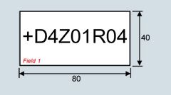
Y32
Two-line label for system identification, 40 × 180 mmResopal labeling plates (white with black lettering) for identifying Cabinet Modules are available. The labels are stuck to the cabinet door.
Dimensions H × W: 40 × 180 mm
The text must be specified in plain text when ordering.
Field 1: Max. 9 characters, font size 10 mm
Field 2: Max. 9 characters, font size 10 mm
Field 3: Max. 20 characters, font size 10 mm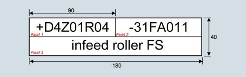
Y33
Four-line label for system identification, 40 × 180 mmResopal labeling plates (white with black lettering) for identifying Cabinet Modules are available. The labels are stuck to the cabinet door.
Dimensions H × W: 40 × 180 mm
The text must be specified in plain text when ordering.
Field 1: Max. 9 characters, font size 10 mm
Field 2: Max. 20 characters, font size 6 mm
Field 3: Max. 20 characters, font size 6 mm
Field 4: Max. 20 characters, font size 6 mm
Field 5: Max. 20 characters, font size 6 mm