
- Каталог оборудования Siemens
- Каталог продуктов Siemens Industry
- Приводная техника
- Преобразователи
- Двигатели переменного тока
- Generators
- Мотор-редукторы
- Flender Gear Units
- Couplings
- Technical information
- Selection of the coupling series
- Flexible couplings N-EUPEX and N-EUPEX DS series
- Flexible couplings BIPEX series
- Flexible couplings N-BIPEX series
- Flexible couplings RUPEX series
- Highly flexible couplings ELPEX series
- Highly flexible couplings ELPEX-B series
- Torsionally rigid gear couplings ZAPEX ZW series
- Torsionally Rigid Gear Couplings - ZAPEX ZN Series
- Torsionally rigid all-steel couplings ARPEX series
- SIPEX and BIPEX-S Backlash-free Couplings
- Non-positively acting couplings FLUDEX
- Taper clamping bushes
- Инструментальное программное обеспечение
- Дополнительные компоненты
- Техника автоматизации
- Energy
- Автоматизация и безопасность зданий
- Низковольтная коммутационная техника
- Технология безопасности
- Системные решения и продукты для отраслей
- Сервис
- Приводная техника
Flexible Couplings - BIPEX-S Series
- Информационные материалы
Информационные материалы

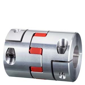
BIPEX-S couplings are torsionally flexible and are free of backlash in the pretensioned state. They are characterized by their compact design and high power density. BIPEX-S couplings connect machine shafts and compensate for shaft misalignment that can occur during assembly or operation. The damping properties of the couplings can be varied by the use of cam rings made of elastomer of various degrees of hardness.
BIPEX-S couplings are suitable for all drive applications which require a coupling that offers positioning accuracy and vibration damping.
Область применения

BIPEX-S couplings within the standard catalog range are available in 10 sizes with torque ratings ranging from 0.5 to 655 Nm. The coupling is suitable for ambient temperatures of between -30 °C and +90 °C. Cam rings with alternative hardness grades can be supplied for ambient temperatures down to -50 °C or up to +120 °C.
BIPEX-S couplings are ideal for use in servo drives, linear axes or rotary encoders of the type typically deployed in machine tools, packaging machines or printing presses.
Дизайн
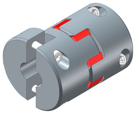
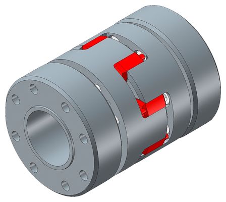
BIPEX-S couplings each comprise two hub parts connected by a cam ring made of polyurethane (PU).
The couplings can be axially plugged in during assembly. The hubs can be coupled to the shafts by many different methods including set screws, key joint, slotted clamping hubs, half-shell hubs, clamping hubs or expanding hubs.
BIPEX-S couplings are positive-locking and torsionally flexible thanks to the polyurethane cam ring. Misalignment between the connected shafts deforms the cam ring.
Coupling materials:
Hubs:
Up to size 38 aluminum
Sizes 42 and 48 steelCam ring:
PU 80 ShoreA -50 °C to +80 °C
PU 92 ShoreA -40 °C to +90 °C
PU 98 ShoreA -30 °C to +90 °C
(standard ring)
PU 64 ShoreD -50 °C to +120 °CThe coupling types can be combined from the available range of hub versions and different elastomer grades.
Hub versions:
N: Hub with set screw
G: Slotted clamping hub
C: Slotted clamping hub, compakt
H: Half-shell clamping hub
K: Clamping hub with external taper
S: Expanding hubVersions N, G, C and H are optionally available with keyway.
BIPEX-S coupling versions
Type
Description
BNN 1)
Hub with set screw on both sides
BGG 1)
Clamping hub on both sides
BCC 1)
Compact clamping hub on both sides
BHH 1)
Half-shell clamping hubs on both sides
BKK 1)
Clamping hub with external taper on both sides
BCS 1)
Hub 1: Clamping hub/Hub 2: Expanding hub
BHH-W 1)
Drive shaft with half-shell clamping hub
BNG
Hub 1: Set screw/Hub 2: Clamping hub
BNC
Hub 1: Set screw/Hub 2: Compact cl. hub
BNH
Hub 1: Set screw/Hub 2: Half-shell
BNK
Hub 1: Set screw/Hub 2: External taper
BGC
Hub 1: Clamping hub/Hub 2: Compact cl. hub
BGH
Hub 1: Clamping hub/Hub 2: Half-shell
BGK
Hub 1: Clamping hub/Hub 2: External taper
BGS
Hub 1: Clamping hub/Hub 2: Expanding hub
BCH
Hub 1: Cl. hub compact/Hub 2: Half-shell
BCK
Hub 1: Cl. hub compact/Hub 2: External taper
BHK
Hub 1: Half-shell/Hub 2: External taper
BHS
Hub 1: Expanding hub/Hub 2: Half-shell
BKS
Hub 1: Expanding hub/Hub 2: External taper
1) Standard version
Hub variants

Set screw

Clamping hub

Compact camping hub
Half-shell clamping hub
External taper

Expanding hub
Cam rings
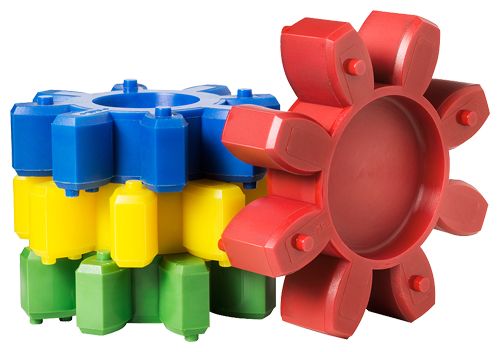
98 ShoreA (red) 92 ShoreA (yellow) 80 ShoreA (blue) 64 ShoreD (green)
Особенности
BIPEX-S couplings are suitable for mounting horizontally, vertically or in any desired position. The coupling parts can be arranged as required on the shaft ends to be connected. The coupling can be axially plugged in.
The cam ring is pretensioned and is therefore assembled without backlash. The cams attached to the cam ring allow the coupling to compensate shaft misalignment, and also provide electrical isolation since they prevent contact between the two hub parts.
BIPEX-S couplings are fail-safe. When the cam ring is worn, the claws of the coupling hubs provide for fail-safe operation.
Available in 4 different Shore hardness grades, the cam rings allow to select the optimum degree of rigidity for any application.
Технические данные
Preliminary dimensioning
Dimensioning according to torque
The coupling must be dimensioned such that the rated torque of the drive including service factors does not exceed the rated torque of the coupling:
TKN ≥ TN × FB × FT
Torque characteristic
Service factor FB
Uniform
1.25
Nonuniform
1.5
Rough
2.0
In order to increase the torsional rigidity and therefore minimize the torsional backlash, it is possible to apply significantly higher service factors for main spindle or positioning drives.
Temperature range
Temperature factor FT
-30 °C to +30 °C
1.0
to +60 °C
1.4
to +80 °C
1.8
to +100 °C
2.0
to +120 °C
2.8
Note:
Please note the permissible temperature ranges of different cam rings.
Starts per hour
Startup factor FA
< 125
1.0
125 to 250
1.3
250 to 500
1.6
500 to 1000
1.8
> 1000
2.0
Checking the peak torques
The coupling size selected during the preliminary dimensioning process must also be suitable with respect to peak torques at the drive and load ends:
TKN ≥ TS × FB × FT
TS = TAS × JL : (JA + JL)× FA or TS = TLS × JA : (JA + JL)× FA
Checking the maximum speed
For all load situations nKmax > nmax
Checking the permitted shaft misalignment
The actual shaft misalignment must be less than the permitted shaft misalignment for all load situations.
Checking the shaft-hub connection
In the case of clamping connections without feather key, it must be ensured that the transmissible torque of the hub connection is greater than the peak torque at the coupling.
Formula symbols
Key to formula symbols
Name
Formula symbols
Unit
Explanation
Rated coupling torque
TKN
Nm
Torque which can be transmitted as static torque by the coupling over the period of use.
Coupling overload torque
TKOL
Nm
Torque which can be transmitted very rarely as maximum torque by the coupling.
Peak torque at drive end
TAS
Nm
Peak torque during non-periodic torque surges at drive end
Peak torque at load end
TLS
Nm
Peak torque during non-periodic torque surges at load end
Peak torque
TS
Nm
Peak torque at the coupling
Service factor
FB
Factor that expresses the real coupling load as a ratio of the nominal coupling load
Temperature factor
FT
Factor that takes into account the reduction in strength of flexible rubber materials at higher temperatures
Startup factor
FA
Factor that takes into account additional loading as a function of starting frequency
Moment of inertia of drive end
JA
kgm2
Sum of the moments of inertia at the drive end referred to the coupling speed
Moment of inertia of load end
JL
kgm2
Sum of the moments of inertia at the load end referred to the coupling speed
Torsion angle
φ
°
Torsion angle of the coupling under torsional load
Torsional stiffness, dynamic
CTdyn
Nm/rad
Dynamic torsional stiffness of the coupling
Axial stiffness
Ca
N/mm
Axial stiffness of the coupling
Radial stiffness
Cr
N/mm
Radial stiffness of the coupling
Rated speed
nN
rpm
Coupling speed
Maximum coupling speed
nKmax
rpm
Maximum permissible coupling speed
Axial misalignment
ΔKa
mm
Axial misalignment of the coupling halves
Radial misalignment
ΔKr
mm
Radial misalignment of the coupling halves
Angular misalignment
ΔKw
°
Angular misalignment of the coupling halves
Power ratings
Size
Shore hardness
Rated torque
Maximum torque
Maximum speed
Maximum speed
Maximum speed
Torsional stiffness
Radial stiffness
Permitted shaft misalignment
Type
Type
Type
BNN
BGG, BHH, BCC, BCS
BKK
TKN
TKOL
nKmax
nKmax
nKmax
CTdyn
Cr
ΔKa
ΔKr
ΔKw
Nm
Nm
rmp
rmp
rmp
Nm/rad
N/mm
mm
mm
degrees
5
80 ShoreA
0.3
0.6
47500
38000
-
10
82
0.4
0.12
1.1
92 ShoreA
0.5
1.0
16
154
0.4
0.06
1
98 ShoreA
0.9
1.8
25
296
0.4
0.04
0.9
7
80 ShoreA
0.7
1.4
35000
26000
-
26
114
0.6
0.15
1.1
92 ShoreA
1.2
2.4
43
219
0.6
0.1
1
98 ShoreA
2.0
4.0
69
421
0.6
0.06
0.9
64 ShoreD
2.4
4.8
103
630
0.6
0.04
0.8
9
80 ShoreA
1.8
3.6
24000
18000
-
52
125
0.8
0.19
1.1
92 ShoreA
3.0
6
95
262
0.8
0.13
1
98 ShoreA
5.0
10
155
518
0.8
0.08
0.9
64 ShoreD
6.0
12
224
769
0.8
0.05
0.8
14
80 ShoreA
4.0
8
16000
12000
25000
180
153
1
0.21
1.1
92 ShoreA
7.5
15
344
335
1
0.15
1
98 ShoreA
12.5
25
513
655
1
0.09
0.9
64 ShoreD
16
32
702
855
1
0.06
0.8
19
80 ShoreA
5
10
12000
9500
18500
1030
582
1.2
0.15
1.1
92 ShoreA
10
20
1720
1125
1.2
0.1
1
98 ShoreA
17
34
2580
2010
1.2
0.06
0.9
64 ShoreD
21
42
3720
2950
1.2
0.04
0.8
24
92 ShoreA
35
70
8700
7000
13900
4300
1490
1.4
0.14
1
98 ShoreA
60
120
6190
2550
1.4
0.1
0.9
64 ShoreD
75
150
8930
3695
1.4
0.07
0.8
28
92 ShoreA
95
190
7400
6000
11800
6880
1785
1.5
0.15
1
98 ShoreA
160
320
10310
3210
1.5
0.11
0.9
64 ShoreD
200
400
13050
4350
1.5
0.08
0.8
38
92 ShoreA
190
380
6000
4700
9600
13750
2350
1.8
0.17
1
98 ShoreA
325
650
21490
4410
1.8
0.12
0.9
64 ShoreD
405
810
31620
6475
1.8
0.09
0.8
42
92 ShoreA
265
530
5000
4000
8000
24300
2440
2
0.19
1
98 ShoreA
450
900
48000
5575
2
0.14
0.9
64 ShoreD
560
1120
71700
7280
2
0.1
0.8
48
92 ShoreA
310
620
4600
3500
7100
18055
2590
2.1
0.23
1
98 ShoreA
525
1050
55925
5950
2.1
0.16
0.9
64 ShoreD
655
1310
90500
8280
2.1
0.11
0.8
Torsional stiffness and damping
The values stated in the above table apply to a capacity utilization of 50 %, an excitation amplitude of 10 % TKN with a frequency of 10 Hz and an ambient temperature of 20 °C. The dynamic torsional stiffness is load-dependent and increases in proportion to capacity utilization..
The relative damping coefficient is
ψ = 0.8 for 98, 92 and 80 ShA
ψ = 0.75 for 64 ShD.TKOL is the torque which can be transmitted very rarely as maximum torque by the coupling.
Permitted shaft misalignment
The permitted shaft misalignments ΔKa, ΔKr und ΔKw are maximum values and must not occur simultaneously. The following formula can be used to roughly calculate whether combinations of misalignments are permissible:
(ΔKract : ΔKr) + (ΔKaact : ΔKa) + (ΔKwact : ΔKw) < 1