
- Каталог оборудования Siemens
- Каталог продуктов Siemens Industry
- Приводная техника
- Преобразователи
- Двигатели переменного тока
- Generators
- Мотор-редукторы
- Flender Gear Units
- Couplings
- Technical information
- Selection of the coupling series
- Flexible couplings N-EUPEX and N-EUPEX DS series
- Flexible couplings BIPEX series
- Flexible couplings N-BIPEX series
- Flexible couplings RUPEX series
- Highly flexible couplings ELPEX series
- Highly flexible couplings ELPEX-B series
- Torsionally rigid gear couplings ZAPEX ZW series
- Torsionally Rigid Gear Couplings - ZAPEX ZN Series
- Torsionally rigid all-steel couplings ARPEX series
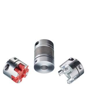
- SIPEX and BIPEX-S Backlash-free CouplingsTorsionally Rigid Couplings - SIPEX SeriesFlexible Couplings - BIPEX-S Series
- SIPEX and BIPEX-S Backlash-free Couplings
- Non-positively acting couplings FLUDEX
- Taper clamping bushes
- Инструментальное программное обеспечение
- Дополнительные компоненты
- Техника автоматизации
- Energy
- Автоматизация и безопасность зданий
- Низковольтная коммутационная техника
- Технология безопасности
- Системные решения и продукты для отраслей
- Сервис
- Приводная техника
SIPEX and BIPEX-S Backlash-free Couplings
- Информационные материалы
Информационные материалы
Article number code
The article number consists of a combination of digits and letters and is divided into three blocks linked by hyphens for better clarity. The coupling series, the type and the size are encoded in blocks 1 and 2. Block 3 contains information applying only to the coupling specified in blocks 1 and 2. The three blocks of the article number are supplemented by information on the bore of the coupling hub parts and information on "Special Types".
The bore details with the code letter L always refer to the bore diameter D1 of the hub part shown on the left on the dimension drawing. The order code beginning with M always refers to the bore diameter D2 of the hub part shown on the right on the dimension drawing.
The order code without the letter "-Z" refers to tolerance H7 without keyway. An exception to this rule is type BNN of series -BIPEX-S to which tolerance H7 with keyway applies.
To order other types with keyway, the letter "-Z" must be appended to the article number.
L40 / M40 = Keyway according to DIN 6885, keyway width JS9
L41 / M41 = Keyway according to DIN 6885, keyway width P9Structure of the Article No.
Place
1
2
3
4
5
6
7
-
8
9
10
11
12
-
13
14
15
16
FLENDER standard couplings
1st to 3rd place
Digit, letter, letterType
2
L
C
4th place
DigitCoupling design
0 ... 9
5th and 6th place
DigitsSeries
SIPEX
BIPEX-S
5
1
9
97th and 8th place
DigitsSize
0
1
20
...
89th and 10th place
LettersType, subassembly or component part
A
A
...
H11th place
DigitShaft-hub connection, flange connection
9
12th place
DigitShaft-hub connection, flange connection, V-belt pulley
9
13th to 16th place
Digit, Letter, Letter, digitFurther technical design details
Z requires order code Q0Y and additional information in plain text for dimension S.0
A
A
B
C
Z0
Bore specifications
Additional order codes for bores finished in delivery condition ∅D1 and ∅D2.
Specification of 9 in the 11th Place of the article number (article number without "-Z" with order codes L.. for ∅D1)
and/or
specification of 9 in the 12th Place of the article number (article number without "-Z" with order codes M.. for ∅D2)
Selection of order code for diameter and tolerance in the following tables under "Bore specifications".Special types
Additional order codes (Article number with "-Z") and, if required, plain text
-
Z
Опции
Bore specifications
Additional identification code with order codes for bore specifications (no letter "-Z" required)
Identification codes with order codes have been specified for the bore specifications.
A bore is ordered by specifying the digit 9 in the 11th and 12th places of the article number and by adding the appropriate order codes for ∅D1 and ∅D2 from the table below.
Unless a different bore tolerance is specified, H7 is selected for all metric bore diameters.
To order a bore diameter other than the values stated in the table, the digit 9 must be specified in the 11th and/or 12th place of the article number; in addition, the letter "-Z" must be added to the article number as well as the order code L9Y with plain text for the left-hand hub and/or order code M9Y with plain text for the right-hand hub.
Bore diameter metric in mm
Bore diameter
Order code for bore diameter
Bore diameter
Order code for bore diameter
Bore diameter
Order code for bore diameter
∅D1
∅D2
∅D1
∅D2
∅D1
∅D2
1
L3L
M3L
16
L0J
M0J
42
L0X
M0X
2
L3M
M3M
18
L0K
M0K
45
L1A
M1A
3
L3N
M3N
19
L0L
M0L
48
L1B
M1B
4
L3P
M3P
20
L0M
M0M
50
L1C
M1C
5
L3Q
M3Q
22
L0N
M0N
55
L1D
M1D
6
L0A
M0A
24
L0P
M0P
60
L1E
M1E
7
L0B
M0B
25
L0Q
M0Q
65
L1F
M1F
8
L0C
M0C
28
L0R
M0R
70
L1G
M1G
9
L0D
M0D
30
L0S
M0S
75
L1H
M1H
10
L0E
M0E
32
L0T
M0T
80
L1J
M1J
11
L0F
M0F
35
L0U
M0U
85
L1K
M1K
12
L0G
M0G
38
L0V
M0V
90
L1L
M1L
14
L0H
M0H
40
L0W
M0W
Unless a different bore tolerance is specified, H7 is selected for all imperial bore diameters.
Bore diameter imperial in Inches
Bore diameter
Order code for bore diameter
Bore diameter
Order code for bore diameter
Bore diameter
Order code for bore diameter
∅D1
∅D2
∅D1
∅D2
∅D1
∅D2
0.1875
L5A
M5A
1.3125
L5T
M5T
2.375
L6N
M6N
0.25
L5B
M5B
1.375
L5U
M5U
2.4375
L6P
M6P
0.3215
L5C
M5C
1.4375
L5V
M5V
2.5
L6Q
M6Q
0.375
L5D
M5D
1.5
L5W
M5W
2.5625
L6R
M6R
0.5
L5E
M5E
1.5625
L5X
M5X
2.625
L6S
M6S
0.5625
L5F
M5F
1.625
L6A
M6A
2.6875
L6T
M6T
0.625
L5G
M5G
1.6875
L6B
M6B
2.75
L6U
M6U
0.6875
L5H
M5H
1.75
L6C
M6C
2.8125
L6V
M6V
0.75
L5J
M5J
1.8125
L6D
M6D
2.875
L6W
M6W
0.8125
L5K
M5K
1.875
L6E
M6E
2.9375
L6X
M6X
0.875
L5L
M5L
1.9375
L6F
M6F
3
L7A
M7A
0.9375
L5M
M5M
2
L6G
M6G
3.0625
L7B
M7B
1
L5N
M5N
2.0625
L6H
M6H
3.125
L7C
M7C
1.0625
L5P
M5P
2.125
L6J
M6J
3.3125
L7D
M7D
1.125
L5Q
M5Q
2.1875
L6K
M6K
3.375
L7E
M7E
1.1875
L5R
M5R
2.25
L6L
M6L
3.4375
L7F
M7F
1.25
L5S
M5S
2.3125
L6M
M6M
3.5
L7G
M7G
Additional identification code with order code for shaft distances (no letter "Z" required.
Order specification with order code Q0Y has been specified for the shaft distance.
Shaft distance is ordered by specifying the letter Z in the 15th place of the article number, adding order code Q0Y and providing additional information in plain text for dimension S (shaft distance).
Ordering example:
SIPEX SHH-W coupling, size 60
Shaft distance S = 1000 mm
Total length LG = 1044 mm
Bore ∅D1 24 H7
Bore ∅D2 28 H7Article-No.:
2LC0591-1AH99-0AZ0
L0P+M0R+Q0Y
Plain text for Q0Y: = 1000 mmТехнические данные
Technical information
Transmissible torques of the different clamping connections as a function of the hub design and shaft diameter
SIPEX series
Size
Hub design
Transmissible torque of clamping connection in Nm
Bore diameter ∅D1/D2 in mm2
3
4
6
8
10
12
14
16
19
20
22
24
25
28
30
32
35
38
40
42
45
48
50
55
60
5
G
-
1.1
1.2
1.4
-
-
-
-
-
-
-
-
-
-
-
-
-
-
-
-
-
-
-
-
-
-
H
-
0.6
0.8
1.3
-
-
-
-
-
-
-
-
-
-
-
-
-
-
-
-
-
-
-
-
-
-
10
G
-
1.1
1.2
1.4
-
-
-
-
-
-
-
-
-
-
-
-
-
-
-
-
-
-
-
-
-
-
H
-
0.6
0.8
1.3
-
-
-
-
-
-
-
-
-
-
-
-
-
-
-
-
-
-
-
-
-
-
15
G
-
2.4
2.5
2.8
3.1
3.3
-
-
-
-
-
-
-
-
-
-
-
-
-
-
-
-
-
-
-
-
H
-
1.1
1.4
2.1
2.8
3.5
4.2
-
-
-
-
-
-
-
-
-
-
-
-
-
-
-
-
-
-
-
20
G
-
4.4
4.6
5.1
5.5
5.9
6.3
-
-
-
-
-
-
-
-
-
-
-
-
-
-
-
-
-
-
-
H
-
1.6
2.2
3.2
4.3
5.4
6.5
-
-
-
-
-
-
-
-
-
-
-
-
-
-
-
-
-
-
-
45
G
-
-
-
8.1
8.6
9.2
9.7
10.3
10.8
-
-
-
-
-
-
-
-
-
-
-
-
-
-
-
-
-
H
-
-
-
5.5
7.4
9.2
11
12.9
14.7
-
-
-
-
-
-
-
-
-
-
-
-
-
-
-
-
-
100
G
-
-
-
10.3
10.8
11.4
11.9
12.5
13.1
13.8
14.2
14.7
-
-
-
-
-
-
-
-
-
-
-
-
-
-
H
-
-
-
5.5
7.4
9.2
11
12.9
14.7
16.6
18.4
20.2
-
-
-
-
-
-
-
-
-
-
-
-
-
-
18
G
-
-
-
-
25.7
26.9
28.1
29.3
30.5
32.3
33
34
35.3
36
-
-
-
-
-
-
-
-
-
-
-
-
H
-
-
-
-
12.2
15.2
18.3
21.3
24.4
29
30.5
33.5
36.6
38
-
-
-
-
-
-
-
-
-
-
-
-
K
-
-
-
-
22
35
50
68
-
-
-
-
-
-
-
-
-
-
-
-
-
-
-
-
-
-
I
-
-
-
-
17
27
39
53
69
-
-
-
-
-
-
-
-
-
-
-
-
-
-
-
-
-
30
G
-
-
-
-
-
42.2
44
45.6
47.3
50
50.7
52.4
54
55
57.4
59
-
-
-
-
-
-
-
-
-
-
H
-
-
-
-
-
21.5
25.8
30.1
34.4
40.9
43
47.3
51.6
53.9
60.2
64.5
-
-
-
-
-
-
-
-
-
-
K
-
-
-
-
-
-
39
53
69
97
108
-
-
-
-
-
-
-
-
-
-
-
-
-
-
-
I
-
-
-
-
-
-
33
44
58
82
90
-
-
-
-
-
-
-
-
-
-
-
-
-
-
-
60
G
-
-
-
-
-
-
93
96
99
104
105
108
112
113
118
121
124
129
-
-
-
-
-
-
-
-
H
-
-
-
-
-
-
47.4
55.3
63.2
75
79
87
95
99
111
119
126
138
-
-
-
-
-
-
-
-
K
-
-
-
-
-
-
-
-
65
92
102
123
147
159
200
229
261
-
-
-
-
-
-
-
-
-
I
-
-
-
-
-
-
63
86
112
158
175
211
251
273
-
-
-
-
-
-
-
-
-
-
-
-
80
G
-
-
-
-
-
-
-
173
178
185
188
193
198
200
207
212
217
225
232
237
242
-
-
-
-
-
H
-
-
-
-
-
-
-
88
100
120
126
138
151
157
176
189
201
220
239
251
264
-
-
-
-
-
K
-
-
-
-
-
-
-
-
-
-
131
159
189
205
257
295
336
402
-
-
-
-
-
-
-
-
I
-
-
-
-
-
-
-
-
-
-
147
178
212
230
289
331
330
394
-
-
-
-
-
-
-
-
150
G
-
-
-
-
-
-
-
172
178
185
188
193
198
200
207
212
217
225
232
237
242
-
-
-
-
-
H
-
-
-
-
-
-
-
88
100
120
126
138
151
157
176
189
201
220
239
251
264
-
-
-
-
-
K
-
-
-
-
-
-
-
-
-
-
131
159
189
205
257
295
336
402
-
-
-
-
-
-
-
-
I
-
-
-
-
-
-
-
-
-
-
147
178
212
230
289
331
330
394
-
-
-
-
-
-
-
-
200
G
-
-
-
-
-
-
-
-
-
-
300
306
313
317
328
335
342
353
364
371
378
389
-
-
-
-
H
-
-
-
-
-
-
-
-
-
-
183
202
220
229
257
275
293
321
348
367
385
413
-
-
-
-
K
-
-
-
-
-
-
-
-
-
-
151
182
217
235
295
339
285
341
402
446
491
-
-
-
-
-
I
-
-
-
-
-
-
-
-
-
-
147
178
212
230
289
331
330
394
395
438
483
-
-
-
-
-
300
G
-
-
-
-
-
-
-
-
-
-
-
-
338
342
353
360
367
378
389
396
403
414
425
432
-
-
H
-
-
-
-
-
-
-
-
-
-
-
-
220
229
257
275
293
321
348
367
385
413
440
458
-
-
K
-
-
-
-
-
-
-
-
-
-
-
-
-
328
412
472
538
643
758
687
757
869
1073
-
-
-
I
-
-
-
-
-
-
-
-
-
-
-
-
-
314
394
452
515
616
726
804
744
854
972
1055
-
-
500
G
-
-
-
-
-
-
-
-
-
-
-
-
-
-
-
-
-
588
603
613
623
638
658
662
687
712
H
-
-
-
-
-
-
-
-
-
-
-
-
-
-
-
-
-
441
478
504
529
567
604
630
692
755
K
-
-
-
-
-
-
-
-
-
-
-
-
-
-
-
-
-
477
562
623
686
788
897
973
1177
-
I
-
-
-
-
-
-
-
-
-
-
-
-
-
-
-
373
425
508
599
664
732
840
884
959
1160
-
800
K
-
-
-
-
-
-
-
-
-
-
-
-
-
-
-
-
-
-
-
-
-
-
-
1773
2146
2553
1400
K
-
-
-
-
-
-
-
-
-
-
-
-
-
-
-
-
-
-
-
-
-
-
-
1773
2146
2553
G = clamping hub
H = half-shell
K = external taper
I = internal taper
BIPEX-S series
Size
Hub design
Transmissible torque of clamping connection in Nm
Bore diameter ∅D1/D2 in mm2
3
4
6
8
10
12
14
16
19
20
22
24
25
28
30
32
35
38
40
42
45
48
50
55
5
G
0.5
0.6
0.6
-
-
-
-
-
-
-
-
-
-
-
-
-
-
-
-
-
-
-
-
-
-
7
G
-
1
1.2
1.3
-
-
-
-
-
-
-
-
-
-
-
-
-
-
-
-
-
-
-
-
-
9
G
-
-
3.1
3.4
3.7
-
-
-
-
-
-
-
-
-
-
-
-
-
-
-
-
-
-
-
-
14
G
-
-
-
5.9
6.3
6.7
7.1
7.8
8
-
-
-
-
-
-
-
-
-
-
-
-
-
-
-
-
C
-
-
-
5.9
6.3
6.7
7.1
7.8
8
-
-
-
-
-
-
-
-
-
-
-
-
-
-
-
-
H
-
-
-
4
5.3
6.6
8
9.2
10.6
-
-
-
-
-
-
-
-
-
-
-
-
-
-
-
-
K
-
-
-
13.2
25
25
37
52
-
-
-
-
-
-
-
-
-
-
-
-
-
-
-
-
-
19
G
-
-
-
-
26
27.5
28.9
30
31.6
33.7
34.5
35.9
-
-
-
-
-
-
-
-
-
-
-
-
-
C
-
-
-
-
23
24
25
26
27.5
29
30
31
-
-
-
-
-
-
-
-
-
-
-
-
-
H
-
-
-
-
21
26.5
31.8
37
42
50
53
58
-
-
-
-
-
-
-
-
-
-
-
-
-
K
-
-
-
-
-
29
56
89
74
129
146
-
-
-
-
-
-
-
-
-
-
-
-
-
-
24
G
-
-
-
-
-
42
44
45.5
47
50
50.5
53
54
55
57
59
-
-
-
-
-
-
-
-
-
C
-
-
-
-
-
42
44
45.5
47
50
50.5
53
54
55
57
59
-
-
-
-
-
-
-
-
-
H
-
-
-
-
-
26.5
31.8
37
42
50
53
58
64
66
74
79
-
-
-
-
-
-
-
-
-
K
-
-
-
-
-
48
71
164
132
234
275
249
327
371
-
-
-
-
-
-
-
-
-
-
-
28
G
-
-
-
-
-
-
-
-
100
105
107
110
113
115
119
122
125
130
135
-
-
-
-
-
-
C
-
-
-
-
-
-
-
-
100
105
107
110
113
115
119
122
125
130
135
-
-
-
-
-
-
H
-
-
-
-
-
-
-
-
78
92
97
107
117
121
136
146
156
178
185
-
-
-
-
-
-
K
-
-
-
-
-
-
-
-
171
276
204
268
341
381
423
509
466
593
738
-
-
-
-
-
-
38
G
-
-
-
-
-
-
-
-
118
122
124
127
130
131
136
139
142
147
152
155
158
163
167
-
-
C
-
-
-
-
-
-
-
-
188
195
197
202
207
210
217
222
227
234
242
247
252
259
267
-
-
H
-
-
-
-
-
-
-
-
78
92
97
107
117
121
136
146
156
178
185
195
204
219
233
-
-
K
-
-
-
-
-
-
-
-
-
-
287
374
474
529
589
708
653
827
827
947
863
1036
1227
-
-
42
G
-
-
-
-
-
-
-
-
-
207
210
215
220
222
230
234
239
247
254
259
264
271
279
284
-
C
-
-
-
-
-
-
-
-
-
-
-
-
-
222
230
234
239
247
254
259
264
271
279
284
-
H
-
-
-
-
-
-
-
-
-
147
155
170
186
193
217
232
248
271
294
309
325
349
372
387
-
K
-
-
-
-
-
-
-
-
-
-
-
-
-
-
532
641
588
750
747
858
802
967
1049
1280
-
48
G
-
-
-
-
-
-
-
-
-
-
-
-
-
345
360
367
374
385
396
403
410
421
432
439
457
C
-
-
-
-
-
-
-
-
-
-
-
-
-
345
360
367
374
385
396
403
410
421
432
439
457
H
-
-
-
-
-
-
-
-
-
-
-
-
-
283
316
339
361
39
429
452
474
509
542
565
621
K
-
-
-
-
-
-
-
-
-
-
-
-
-
-
-
857
1004
1248
1262
1429
1362
1609
1880
1710
2150
G = clamping hub
C = clamping hub compakt
H = half-shell
K = external taper