
- Каталог оборудования Siemens
- Каталог продуктов Siemens Industry
- Приводная техника
- Преобразователи
- Двигатели переменного тока
- Generators
- Мотор-редукторы
- Flender Gear Units
- Couplings
- Technical information
- Selection of the coupling series
- Flexible couplings N-EUPEX and N-EUPEX DS series
- Flexible couplings N-EUPEX and N-EUPEX DS series
- Flexible couplings BIPEX series
- Flexible couplings N-BIPEX series
- Flexible couplings RUPEX series
- Highly flexible couplings ELPEX series
- Highly flexible couplings ELPEX-B series
- Torsionally rigid gear couplings ZAPEX ZW series
- Torsionally Rigid Gear Couplings - ZAPEX ZN Series
- Torsionally rigid all-steel couplings ARPEX series
- SIPEX and BIPEX-S Backlash-free Couplings
- Non-positively acting couplings FLUDEX
- Taper clamping bushes
- Инструментальное программное обеспечение
- Дополнительные компоненты
- Техника автоматизации
- Energy
- Автоматизация и безопасность зданий
- Низковольтная коммутационная техника
- Технология безопасности
- Системные решения и продукты для отраслей
- Сервис
- Приводная техника

Flexible couplings N-EUPEX and N-EUPEX DS series
- Информационные материалы
Информационные материалы

N-EUPEX as overload-holding, fail-safe series

N-EUPEX DS as overload-shedding, non-fail-safe series
N-EUPEX and N-EUPEX DS claw couplings connect machines. They compensate for shaft misalignment, generating only low restorative forces.
The torque is conducted through elastomer flexibles, so the coupling has typically flexible rubber properties.
N-EUPEX couplings are overload-holding. By contrast, the N-EUPEX DS series is designed so that overload or advanced wear causes irreparable damage to the elastomer flexibles. The metal parts of N-EUPEX DS couplings can then rotate freely against one another without contact.
Elastomer flexible of the N-EUPEX series

The flexibles of the N-EUPEX coupling are subjected to compression. If the flexibles are irreparably damaged, the hub parts come into contact with metal. This “emergency operation capability” is required, e.g., in the case of fire pump drives.

Elastomer flexible of the N-EUPEX DS series

The flexibles of the N-EUPEX DS series are subjected to compression and bending forces. If the flexibles are irreparably damaged, the metal parts turn against one another without contact, and the power transmission is separated. Fitting new flexibles will make the coupling once more usable.
The capacity of the N-EUPEX DS series to shed overloads is especially in demand for highly sensitive machines.

Область применения
The N-EUPEX coupling is available as a catalog standard in 23 sizes with a rated torque of between 19 Nm and 62000 Nm. The coupling is suitable for use at ambient temperatures of between –30 °C and +80 °C. By using alternative elastomer buffers, the permissible ambient temperature range can be extended to between –50 °C and +100 °C.
Frequently, the coupling is used to connect the motor to the gear unit input shaft. The coupling is suitable especially for drives with uniform to average dynamic loads. Examples of applications are pump drives, ventilator drives or crane running gear. Furthermore, N-EUPEX couplings can be used as add-on couplings, particularly on FLUDEX fluid couplings or ARPEX AKR safety couplings. In the case of drives with a diesel engine, N-EUPEX couplings are suitable for driven machines with a low mass moment of inertia.
In the case of diesel engine drives, the actual dynamic coupling load should be checked by measurement or torsional vibration calculations.

Coupling suitable for potentially explosive environments. Complies with Directive 94/9/EC for:


II 2 G T4 / T5 / T6 D120 °C
–30 °C ≤ Ta ≤ +80 °C / +50 °C / +40 °C
I M2
Дизайн
N-EUPEX and N-EUPEX DS couplings consist of two hub parts mounted on the machine shafts. The coupling parts are connected positively by means of elastomer flexibles. On the twopart variant, the elastomer flexibles can be changed only if one of the coupled machines is moved. On the three-part variants, the bolted cam ring can be released and moved to enable the flexible to be changed without moving the coupled machines.
Materials
Cam parts, pocket parts, adapters and hubs
Grey cast iron EN-GJL-250
Flexible materials
- N-EUPEX Series
Material/description
Hardness
Identification
Ambient temperature
NBR standard type
80 Shore A
Flexible black with blue stripe
–30 °C … +80 °C
NBR soft
65 Shore A
Flexible black with green stripe
–30 °C … +80 °C
NBR hard
90 Shore A
Flexible black with magenta stripe
–30 °C … +80 °C
NBR normal low backlash
80 Shore A
Flexible black with yellow stripe
–30 °C … +80 °C
NBR soft low backlash
65 Shore A
Flexible black with white stripe
–30 °C … +80 °C
NR for low temperature
80 Shore A
Flexible black with orange stripe
–50 °C … +50 °C
HNBR high temperature
80 Shore A
Flexible black with red stripe
–10 °C … +100 °C
- N-EUPEX DS Series
Material/description
Hardness
Identification
Ambient temperature
NBR compound flexibles
for size 66 … 27280/90 ShoreA
2 componentsFlexible black
–30 °C … +80 °C
NBR hard
for size 305 ... 55690 Shore A
Flexible black
–30 °C … +80 °C
PU electrically insulating
95 Shore A
Flexible blue
–30 °C … +50 °C
PU elastomer flexibles in special design on request.
The technical data and the product codes do not include the flexible variants NBR low backlash, HNBR high temperature and
NR low temperature and the DS flexibles polyurethane electrically insulating.Technical data, prices and product codes on request.
Brake disks
EN-GJS-400 spheroidal graphite cast iron or S355J2G3 steel
Brake drums
Grey cast iron EN-GJL-250
Low-temperature application
Shock loads in the drive caused by e.g. starting of drives with large masses to be accelerated (e.g. in fan drives) result in high component loads, particularly at low temperatures.
For such applications a particularly robust coupling series must be selected. Of the flexible couplings, the RUPEX pin-and-bush coupling is especially suited for this.Types of N-EUPEX claw coupling
Type
Description
A
Fail-safe, 3-part
B
Fail-safe, 2-part
D
Fail-safe. 3-part, flange variant
E
Fail-safe. 2-part, flange variant
H
Fail-safe, with adapter
O
Fail-safe, 2-part, with brake drum
P
Fail-safe, 3-part, with brake drum
EBD
Fail-safe, 2-part, with brake disk
DBD
Fail-safe, 3-part, with brake disk
DBDR
Fail-safe, 3-part, with brake disk, brake disk radially dismountable
ADS
Non-fail-safe, 3-part
BDS
Non-fail-safe, 2-part
HDS
Non-fail-safe, with adapter
Further application-related coupling types are available. Dimension sheets for and information on these are available on request.
Types of N-EUPEX claw coupling on request
Type
Description
AT
Fail-safe, 3-part, with Taper clamping bush
BT
Fail-safe, 2-part, with Taper clamping bush
G
Fail-safe, 2-part, with intermediate shaft
F
Fail-safe, 3-part, with intermediate shaft
K
Fail-safe, 3-part, with brake drum to customer's requirement
L
Fail-safe, 2-part, with brake drum to customer's requirement
M
Fail-safe, 2-part, with flange dimensions to SAE J620d
Modular principle of N-EUPEX types


Types A and ADS
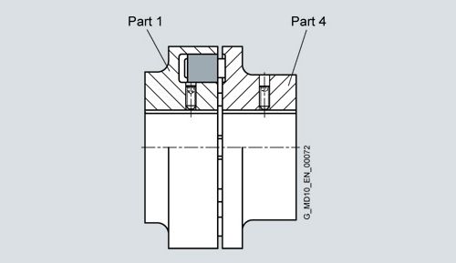
Types B and BDS
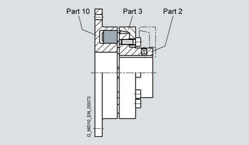
Type D

Type E
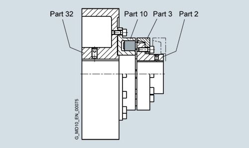
Type P
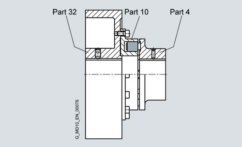
Type O

Type DBDR

Type DBD

Type EBD

Types H and HDS
Further application-related coupling types are available. Dimension sheets for and information on these are available on request.
Функции
The motor torque is transmitted to the hub at the drive end via the shaft-hub connection, which is mostly designed as a keyway connection. The torque is transmitted to the hub on the output side with the aid of elastomer flexibles. The hub on the output side further transmits the torque to the driven machine or a gear unit placed in between. Because of the primarily compressionloaded elastomer flexibles, the coupling has a progressive torsional stiffness.
In the case of the N-EUPEX DS coupling series, the elastomer flexible is subjected to bending and compression loads. In the event of overload or advanced wear, the coupling disconnects positively and the flexibles are irreparably damaged. The metal parts then rotate without touching one another. After new elastomer flexibles are fitted, the N-EUPEX DS coupling is once more operable.
N-EUPEX DS couplings are maintenance-free, even in potentially explosive environments, so long as the possible torque interruption does not lead to an unacceptable disruption of the production process.
Особенности
N-EUPEX couplings are designed on the modular principle and have a very simple construction. N-EUPEX types are made up of subassemblies to suit requirements. The couplings are assembled by simply fitting the coupling halves together. Wear is restricted to the elastomer flexibles, which must be replaced at the end of their service life.
Depending on type, the elastomer flexibles can be changed without moving the coupled machines.
The coupling parts are readily available from stock and are mostly finish-machined, i.e. with finished bore, keyway, set screw and balancing.Optionally:
The wear indicator for N-EUPEX couplings enables the condition of the flexible to be easily assessed. The wear condition can also be ascertained with the aid of a stroboscope while the coupling is rotating. The production process can thus continue undisturbed.
If the stroboscope is to be used in a potentially explosive environment, you can enquire about the equipment for this at FLENDER.

The wear indicator must be attached to the outside diameter of the coupling after the coupling has been fitted.
Технические данные
Power ratings of the N-EUPEX series
Size
Rated torque for
flexible typeTorsional stiffness at 50 %
capcity utilization for flexible typeAssembly
Permitted shaft alignment at n = 1500 rpm 1)
65 ShoreA
80 ShoreA
90 ShoreA
65 ShoreA
80 ShoreA
90 ShoreA
Gap dimension 2)
Axial
Radial
Angle
TKN
TKN
TKN
CTdyn 50 %
CTdyn 50 %
CTdyn 50 %
ΔS
ΔKa
ΔKr
ΔKw
Nm
Nm
Nm
kNm/rad
kNm/rad
kNm/rad
mm
mm
mm
°
58
11
19
19
0.21
0.50
0.93
1.0
0.2
0.2
0.15
68
21
34
34
0.39
0.90
1.80
1.0
0.2
0.2
0.15
80
37
60
60
1.05
2.40
4.50
1.0
0.2
0.2
0.12
95
63
100
100
1.64
4.00
7.40
1.0
0.2
0.2
0.12
110
100
160
160
2.49
6.00
11.40
1.0
0.2
0.2
0.10
125
150
240
240
3.70
9.00
17
1.0
0.25
0.25
0.10
140
230
360
360
5.60
13.2
25
1.0
0.25
0.25
0.10
160
350
560
560
11.2
26.7
51
2.0
0.3
0.3
0.10
180
550
880
880
19.2
46
88
2.0
0.3
0.3
0.10
200
850
1340
1340
31.6
75
139
2.0
0.3
0.3
0.09
225
1260
2000
2000
48
115
212
2.0
0.35
0.35
0.09
250
1760
2800
2800
68
162
302
2.5
0.35
0.35
0.08
280
2460
3900
3900
95
226
420
2.5
0.4
0.4
0.08
315
3500
5500
5500
171
370
730
2.5
0.4
0.4
0.08
350
4850
7700
7700
235
520
950
2.5
0.5
0.5
0.08
400
6500
10300
10300
316
750
1420
2.5
0.5
0.5
0.08
440
8500
13500
13500
390
930
1920
2.5
0.6
0.6
0.08
480
10500
16600
16600
510
1200
2300
2.5
0.6
0.6
0.07
520
13300
21200
21200
600
1410
2710
2.5
0.65
0.65
0.07
560
18300
29000
29000
1000
2340
4400
3.0
0.65
0.65
0.07
610
24000
38000
38000
1300
3030
5700
3.0
0.75
0.75
0.07
660
30900
49000
49000
1640
3800
7100
3.0
0.8
0.8
0.07
710
39000
62000
62000
2140
4900
9100
3.0
0.9
0.9
0.07
1) The maximum speed of the respective type must be noted. For further information on permissible shaft misalignment, please see the operating instructions.
2) Does not apply to type H.
For maximum coupling torque: TKmax = 3.0 · TKN
For coupling overload torque: TKOL = 3.5 · TKN
For coupling fatique torque: TKW = 0.15 · TKN, where TN > TW must be adhered to.
Torsional stiffness and damping
The values stated in the above table apply to a capacity utilization of 50 %, an excitation amplitude of 10 % TKN with the frequency 10 Hz and an ambient temperature of 20 °C. Dynamic torsional stiffness is dependent on load and increases in proportion to capacity utilization. The following table shows the correction factors for different nominal loads.
CTdyn = CTdyn 50 % · FKC
Capacity utilization TN/TKN
20 %
40 %
50 %
60 %
70 %
80 %
100 %
Correction factor FKC
65/80/90 ShoreA0.54
0.84
1.00
1.18
1.36
1.55
1.97
The damping coefficient is Ψ = 1.4
Furthermore, torsional stiffness and damping depend on the ambient temperature and the frequency and amplitude of the torsional vibration excitation. More precise torsional stiffness and damping parameters on request
Permitted shaft misalignment
The permitted shaft misalignment depends on the operating speed. As the speed increases, lower shaft misalignment values are permitted. The following table shows the correction factors for different speeds.
The maximum speed for the respective coupling size must be observed!ΔKperm = ΔK1500 · FKV
Speed in rpm
500
1000
1500
3000
Correction factor FKV
1.7
1.2
1.0
0.70
The axial misalignment may occur dynamically at frequencies up to 10 Hz. For fitting a maximum gap dimension of Smax = S + ΔS and a minimum gap dimension of Smin = S – ΔS is permitted. Shaft misalignments ΔKa, ΔKr and ΔKw may occur simultaneously.
Power ratings of the N-EUPEX DS series
Size
Rated torque
Torsional stiffness at 50 %
capcity utilizationAssembly
Permitted shaft misalignment at
speed n = 1500 rpmGap dimension 1)
Axial
Radial
Angel
TKN
CTdyn
ΔS
ΔKa
ΔKr
ΔKw
Nm
kNm/rad
mm
mm
mm
°
66
19
0.73
1.0
0.2
0.2
0.15
76
34
1.36
1.0
0.2
0.2
0.15
88
60
2.62
1.0
0.2
0.2
0.12
103
100
4.00
1.0
0.2
0.2
0.12
118
160
6.30
1.0
0.2
0.2
0.10
135
240
10.5
1.0
0.25
0.25
0.10
152
360
13.6
1.0
0.25
0.25
0.10
172
560
27.2
2.0
0.3
0.3
0.10
194
880
47.0
2.0
0.3
0.3
0.10
218
1340
70.0
2.0
0.3
0.3
0.09
245
2000
106
2.0
0.35
0.35
0.09
272
2800
149
2.5
0.35
0.35
0.08
305
3900
214
2.5
0.4
0.4
0.08
340
5500
350
2.5
0.4
0.4
0.08
380
7700
480
2.5
0.5
0.5
0.08
430
10300
730
2.5
0.5
0.5
0.08
472
13500
990
2.5
0.6
0.6
0.08
514
16600
1270
2.5
0.6
0.6
0.07
556
21200
1540
2.5
0.65
0.65
0.07
1) Does not apply to type HDS.
Flexibles of sizes 66 to 272 are of the compound type with a hard core and soft thrust pieces.
Sizes 305 to 556 are of 90 ShoreA NBR material.For maximum coupling torque: TKmax = 2.0 · TKN
For coupling overload torque: TKOL = 3.0 · TKN
For coupling fatigue torque: TKW = 0.15 · TKN
Torsional stiffness and damping
The values stated in the above table apply to a capacity utilization of 50 %, an excitation amplitude of 10 % TKN with the frequency 10 Hz and an ambient temperature of 20 °C. Dynamic torsional stiffness is dependent on the load and increases in proportion to capacity utilization. The following table shows the correction factors for different rated loads.
CTdyn = CTdyn 50 % · FKC
Capacity utilization TN / TKN
20 %
40 %
50 %
60 %
70 %
80 %
100 %
Correction factor FKC
0.7
0.9
1
1.1
1.2
1.3
1.5
The damping coefficient isΨ = 1,4
Torsional stiffness and damping is further dependent on the ambient temperature and the frequency and amplitude of the torsional vibration excitation. More precise torsional stiffness and damping parameters on request.Permitted shaft misalignment
The permitted shaft misalignment depends on the operating speed. As the speed increases, lower shaft misalignment values are permitted. The following table shows the correction factors for different speeds.
The maximum speed for the respective coupling size must be noted!ΔKperm = ΔK1500 · FKV
Speed in rpm
500
1000
1500
3000
Correction factor FKV
1.6
1.20
1.0
0.70
The axial misalignment must occur dynamically at frequencies up to 10 Hz. For fitting a maximum gap dimension of Smax = S + ΔS and a minimum gap dimension of Smin = S – ΔS are permitted.
Shaft misalignment ΔKa, ΔKr and ΔKw may occur simultaneously.
Assignment of N-EUPEX sizes to IEC standard motors
The assignment applies to an application factor of 1.25.
Outputs PM of IEC motors and assigned N-EUPEX couplings
Three-phase motor
Output at ≈ 3000 rpm
N-EUPEX coupling
Output at ≈ 1500 rpm
N-EUPEX coupling
Output at ≈ 1000 rpm
N-EUPEX coupling
Output at ≈ 750 rpm
N-EUPEX coupling
DE shaft end D x E to IEC
Size
PM
Size
PM
Size
PM
Size
PM
Size
D
E
kW
kW
kW
kW
mm
mm
56
0.09
58
0.06
58
9
20
0.12
58
0.09
58
63
0.18
58
0.12
58
11
23
0.25
58
0.18
58
71
0.37
58
0.25
58
14
30
0.55
58
0.37
58
80
0.75
58
0.55
58
0.37
58
19
40
1.1
58
0.75
58
0.55
58
90S
1.5
68
1.1
68
0.75
68
24
50
90L
2.2
68
1.5
68
1.1
68
24
50
100L
3
80
2.2
80
1.5
80
0.75
80
28
60
3
80
1.1
80
112M
4
80
4
80
2.2
80
1.5
80
28
60
132S
5.5
95
5.5
95
3
95
2.2
95
38
80
7.5
95
132M
7.5
95
4
95
3
95
38
80
5.5
95
160M
11
95
11
95
7.5
95
4
95
42
110
15
95
5.5
95
160L
18.5
95
15
110
11
110
7.5
110
42
110
180M
22
110
18.5
110
48
110
180L
22
125
15
125
11
125
48
110
200L
30
125
30
125
18.5
125
15
125
55
110
37
125
22
140
225S
37
140
18.5
140
55
110
60
140
225M
45
125
45
140
30
140
22
140
55
110
60
140
250M
55
140
55
160
37
160
30
160
60
140
65
140
280S
75
160
75
180
45
180
37
180
65
140
75
140
280M
90
160
90
180
55
180
45
180
65
140
75
140
315S
110
160
110
200
75
200
55
200
65
140
80
170
315M
132
160
132
200
90
200
75
200
65
140
80
170