
- Каталог оборудования Siemens
- Каталог продуктов Siemens Industry
- Приводная техника
- Преобразователи
- Двигатели переменного тока
- Generators
- Мотор-редукторы
- Flender Gear Units
- Couplings
- Technical information
- Selection of the coupling series
- Flexible couplings N-EUPEX and N-EUPEX DS series
- Flexible couplings BIPEX series
- Flexible couplings N-BIPEX seriesType BWNSpare and wear parts
- Flexible couplings N-BIPEX series
- Flexible couplings RUPEX series
- Highly flexible couplings ELPEX series
- Highly flexible couplings ELPEX-B series
- Torsionally rigid gear couplings ZAPEX ZW series
- Torsionally Rigid Gear Couplings - ZAPEX ZN Series
- Torsionally rigid all-steel couplings ARPEX series
- SIPEX and BIPEX-S Backlash-free Couplings
- Non-positively acting couplings FLUDEX
- Taper clamping bushes
- Инструментальное программное обеспечение
- Дополнительные компоненты
- Техника автоматизации
- Energy
- Автоматизация и безопасность зданий
- Низковольтная коммутационная техника
- Технология безопасности
- Системные решения и продукты для отраслей
- Сервис
- Приводная техника
Flexible couplings N-BIPEX series
- Информационные материалы
Информационные материалы

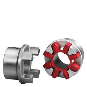
Flexible couplings, N-BIPEX
N-BIPEX couplings are torsionally flexible and are outstanding for their particularly compact design and low weight.
N-BIPEX couplings are used in many areas of mechanical engineering.
Their main area of use is in electric motor drives which are well aligned and have uniform torque loads, such as in hydraulic applications and in combinations with geared motors.
Область применения

Cam rings, 92 ShoreA, 95 ShoreA, 64 ShoreD
The N-BIPEX coupling is available as a catalog standard in 10 sizes with rated torques of between 12 Nm and 4650 Nm and is made of high-grade spheroidal graphite cast iron.
The extremely high-performance cam ring materials are available from stock in three different Shore hardnesses with the following colors:
- 92 ShoreA – red
- 95 ShoreA – gren
- 64 ShoreD – blue

Cam rings, 92 ShoreA
An additional size marking has been provided on the outer surface of the cam ring to be able to determine the size of the N-BIPEX even when it is in the assembled state without having to use any additional aids.
The coupling is suitable for use at ambient temperatures between -50 °C and +100 °C without any restrictions on the rated torque as a result of temperature factors.
Coupling suitable for use in potentially explosive atmospheres.
Complies with the current ATEX Directive for:

II 2 G IIB T4/T5/T6
-50 °C ≤ Ta ≤ +100 °C/+70 °C/+55 °CII 2D T 120°C
-50 °C ≤ Ta ≤ +90 °CI M2
Дизайн
The N-BIPEX coupling of type BWN comprises two identical hub parts connected by a cam ring of elastomer material.
The hubs are connected to the respective shafts via finished bores with parallel keyway connection.
N-BIPEX couplings are positive-locking and torsionally flexible thanks to the thermoplastic polyurethane cam ring.
Coupling materials
Hubs
EN-GJS-400-15
Cam ring
- TPU 92 ShoreA -50 °C to +100 °C without any restrictions
- TPU 95 ShoreA -50 °C to +100 °C without any restrictions
- TPU 64 ShoreD -50 °C to +100 °C without any restrictions

N-BIPEX, Type BWN, flexible couplings
Size
Undrilled
Preferred bores from stock with cylindrical finished bores ∅ in mm H7, parallel keyway according to DIN 6885-1 JS9 and set screw
10
11
12
14
15
16
17
18
19
20
22
24
25
28
30
32
35
38
40
42
45
48
50
55
60
65
70
75
80
85
90
100
110
120
19
✓
✓
✓
✓
✓
✓
✓
✓
✓
✓
✓
✓
✓
✓
24
✓
✓
✓
✓
✓
✓
✓
✓
✓
✓
✓
✓
✓
✓
✓
✓
✓
28
✓
✓
✓
✓
✓
✓
✓
✓
✓
✓
✓
✓
✓
✓
✓
✓
✓
38
✓
✓
✓
✓
✓
✓
✓
✓
✓
✓
✓
✓
✓
✓
✓
✓
✓
✓
42
✓
✓
✓
✓
✓
✓
✓
✓
✓
✓
✓
✓
✓
✓
✓
✓
48
✓
✓
✓
✓
✓
✓
✓
✓
✓
✓
✓
✓
✓
✓
✓
55
✓
✓
✓
✓
✓
✓
✓
✓
✓
✓
✓
✓
✓
✓
✓
✓
65
✓
✓
✓
✓
✓
✓
✓
✓
✓
✓
✓
✓
✓
✓
✓
75
✓
✓
✓
✓
✓
✓
✓
✓
✓
✓
✓
✓
✓
✓
✓
✓
90
✓
✓
✓
✓
✓
✓
✓
✓
✓
✓
✓
✓
✓
✓
✓
✓ Preferred bores
Функции
The torque is transmitted to the hub at the drive end via the shaft-hub connection, which is mostly designed as a keyway connection, and is transmitted to the hub on the output side via the cam ring. This hub then further transmits the torque to the driven machine or a gear unit placed in between. The special cam design helps to keep the compression-loaded cam ring elements in their defined position under all operating conditions and to keep them evenly loaded. This results in a long lifetime of the flexible elements. A long lifetime is also guaranteed by the hub parts which ensure maximum operational reliability even under harsh operating conditions.
Особенности
N-BIPEX couplings are suitable for horizontal, vertical and freely selectable mounting positions. They are able to absorb axial, radial and angular misalignment.
N-BIPEX couplings consist of two identical hub parts which can be arranged as required on the shaft extensions to be connected. N-BIPEX couplings transmit the torque positively and are thus fail-safe. The curved design of the cast cams ensures that the N-BIPEX couplings have a perfect pressure distribution and this increases the elastomer lifetime.
The flexible cam rings responsible for torque transmission and misalignment compensation are available in different Shore hardnesses. As a result of the good damping capability and by selecting the suitable stiffness, torque shock loads can thus be absorbed and the torsional vibration behavior of the drive can be positively influenced. Different cam ring versions and ready-to-install hub parts are available from stock.
Технические данные
Cam rings
Cam rings of polyurethane 92 ShoreA (standard)
Size
Rated torque
Maximum torque
Fatigue torque
Maximum speed
Damping coefficient ψ
Torsional stiffness at 50 % capacity utilization
Permitted shaft misalignment at 1)
V ≤ 45 m/s
< 10 Hz
n = 1500 rpm
TKN
TKmax
TKW
nmax
CTdyn 50 %
ΔKa
ΔKr
ΔKw
Nm
Nm
Nm
rpm
Nm/rad
mm
mm
degrees
19
12
36
2
19500
1.4
530
0.30
0.17
0.5
24
45
135
7
14500
1.4
1790
0.40
0.23
0.5
28
95
285
14
12500
1.4
3060
0.50
0.25
0.5
38
190
570
29
10000
1.4
6500
0.60
0.29
0.5
42
265
795
40
8500
1.4
8200
0.70
0.34
0.5
48
330
990
50
7500
1.4
10000
0.80
0.38
0.5
55
460
1380
70
6500
1.4
14500
0.90
0.40
0.5
65
670
2010
100
6000
1.4
25600
1.00
0.45
0.5
75
1400
4200
210
5000
1.4
37400
1.20
0.52
0.5
90
2500
7500
375
4000
1.4
62700
1.40
0.60
0.5
1) DThe maximum speed must be observed. Please refer to the Operating Instructions for further information on permitted shaft misalignment.
Cam rings of polyurethane 95 ShoreA (Ordering option -Z and order code K01)
Size
Rated torque
Maximum torque
Fatigue torque
Maximum speed
Damping coefficient ψ
Torsional stiffness at 50 % capacity utilization
Permitted shaft misalignment at 1)
V ≤ 45 m/s
< 10 Hz
n = 1500 rpm
TKN
TKmax
TKW
nmax
CTdyn 50 %
ΔKa
ΔKr
ΔKw
Nm
Nm
Nm
rpm
Nm/rad
mm
mm
degrees
19
18
54
3
19500
1.4
1130
0.27
0.15
0.4
24
65
195
10
14500
1.4
4240
0.36
0.21
0.4
28
160
480
25
12500
1.4
8050
0.45
0.23
0.4
38
325
975
50
10000
1.4
14100
0.54
0.26
0.4
42
450
1350
70
8500
1.4
16200
0.63
0.31
0.4
48
550
1650
85
7500
1.4
23300
0.72
0.34
0.4
55
700
2100
105
6500
1.4
28500
0.81
0.36
0.4
65
1000
3000
150
6000
1.4
35000
0.90
0.41
0.4
75
2000
6000
300
5000
1.4
66300
1.08
0.47
0.4
90
3700
11100
555
4000
1.4
105000
1.26
0.54
0.4
1) The maximum speed must be observed. Please refer to the Operating Instructions for further information on permitted shaft misalignment.
Cam rings of polyurethane 64 ShoreD (Ordering option -Z and order code K04)
Size
Rated torque
Maximum torque
Fatigue torque
Maximum speed
Damping coefficient ψ
Torsional stiffness at 50 % capacity utilization
Permitted shaft misalignment at 1)
V ≤ 45 m/s
< 10 Hz
n = 1500 rpm
TKN
TKmax
TKW
nmax
CTdyn 50 %
ΔKa
ΔKr
ΔKw
Nm
Nm
Nm
rpm
Nm/rad
mm
mm
degrees
19
25
75
5
19500
1.4
2010
0.24
0.14
0.3
24
90
270
15
14500
1.4
7680
0.32
0.18
0.3
28
200
600
30
12500
1.4
12200
0.40
0.20
0.3
38
405
1215
60
10000
1.4
25100
0.48
0.23
0.3
42
560
1680
84
8500
1.4
32000
0.56
0.27
0.3
48
700
2100
105
7500
1.4
41200
0.64
0.30
0.3
55
925
2775
140
6500
1.4
52600
0.72
0.32
0.3
65
1200
3600
180
6000
1.4
86700
0.80
0.36
0.3
75
2600
7800
390
5000
1.4
143000
0.96
0.42
0.3
90
4650
13950
700
4000
1.4
234000
1.12
0.48
0.3
1) The maximum speed must be observed. Please refer to the Operating Instructions for further information on permitted shaft misalignment.
Torsional stiffness and damping
The values stated in the above table apply to a capacity utilization of 50 %, an excitation amplitude of 10 % TKN with frequency 10 Hz and an ambient temperature of 20 °C. The dynamic torsional stiffness (CTdyn) is load-dependent and increases in proportion to capacity utilization. The following table shows the correction factors for different nominal load.
CTdyn = CTdyn 50 % • FKC
Capacity utilization TN / TKN
20 %
40 %
50 %
60 %
70 %
80 %
100 %
Correction factor FKC
92/95 ShoreA and 64 ShoreD0.56
0.85
1.00
1.17
1.35
1.53
1.92
Furthermore, torsional stiffness and damping depend on the ambient temperature, the frequency and the amplitude of the torsional vibration excitation. More precise torsional stiffness and damping parameters on request.
With flexible couplings the manufacturing process of the rubber elements and their aging primarily influence the stiffness value CTdyn. For this reason calculation must be made with a tolerance for the dynamic stiffness of ±20 %. The specified damping coefficient ψ is a minimum value with the result that the damping performance of the coupling corresponds at least to the specified value.
Permitted shaft misalignment
The permitted shaft misalignment depends on the operating speed. As the speed increases, lower shaft misalignment values are permitted. The following table shows the correction factors for different speeds. The maximum speed depending on the respective coupling size and type must be observed!
ΔKzul = ΔK1500 • FKV
Speed in rpm
500
1000
1500
3000
Correction factor FKV
1.20
1.10
1.00
0.7
The axial misalignment may occur dynamically at frequencies up to 10 Hz. For fitting, the maximum gap dimension of S2 max. = S2 + ΔS2 and the minimum gap dimension of S2 min. = S2 - ΔS2 are permitted.
The shaft misalignments ΔKa, ΔKr und ΔKw may occur simultaneously (see under "Couplings"/"Technical Informations"/"Shaf misalignment").
Assignment of N-BIPEX sizes to output PM of IEC standard motors
The assignment applies for an service factor of 1.25 and the use of a standard cam ring (92 ShoreA).
Three-phase motor
Motor
N-BIPEX coupling
Motor
N-BIPEX coupling
Motor
N-BIPEX coupling
Motor
N-BIPEX coupling
DE shaft end D × E acc. to IEC
Size
Output at ≈ 3000 rpm
Size
Output at ≈ 1500 rpm
Size
Output at ≈ 1000 rpm
Size
Output at ≈ 750 rpm
Size
PM
T
PM
T
PM
T
PM
T
D
E
kW
Nm
kW
Nm
kW
Nm
kW
Nm
mm
mm
80
0.75
2.5
19
0.55
3.7
19
0.37
3.9
19
0.18
2.5
19
19
40
1.1
3.7
19
0.75
5.1
19
0.55
5.8
19
0.25
3.5
19
19
40
90S
1.5
5.5
19
1.1
7.5
19
0.75
8
19
0.37
5.3
19
19
40
1.5
5.5
19
1.1
7.5
19
0.75
8
19
0.37
5.3
19
24
50
90L
2.2
7.4
19
1.5
10
24
1.1
12
24
0.55
7.9
24
19
40
2.2
7.4
19
1.5
10
24
1.1
12
24
0.55
7.9
24
24
50
100L
3
9.8
24
2.2
15
24
1.5
15
24
0.75
11
24
28
60
3
20
24
1.5
15
24
1.1
16
24
28
60
112M
4
13
24
4
27
24
2.2
22
24
1.5
21
24
28
60
132S
5.5
18
28
5.5
36
28
3
30
28
2.2
30
28
38
80
7.5
25
28
132M
7.5
49
28
4
40
28
3
40
28
38
80
5.5
55
28
38
80
160M
11
36
38
11
72
38
7.5
75
38
4
54
38
42
110
15
49
38
5.5
74
38
42
110
160L
18.5
60
38
15
98
38
11
109
38
7.5
100
38
42
110
180M
22
71
38
18.5
121
38
48
110
180L
22
144
38
15
148
42
11
145
42
48
110
200L
30
97
42
30
196
42
18.5
181
42
15
198
42
55
110
37
120
42
22
215
42
55
110
225S
37
240
48
18.5
244
48
60
140
225M
45
145
42
55
110
45
292
55
30
293
55
22
290
55
60
140
250M
55
177
48
60
140
55
356
55
37
361
55
30
392
65
65
140
280S
75
241
55
65
140
75
484
65
45
438
65
37
483
65
75
140
280M
90
289
55
65
140
90
581
75
55
535
75
45
587
75
75
140
315S
110
353
55
65
140
110
707
75
75
727
75
55
712
75
80
170
315M
132
423
65
65
140
132
849
75
90
873
75
75
971
75
80
170
315L
160
513
65
65
140
200
641
75
65
140
160
1030
75
110
1070
75
90
1170
90
80
170
200
1290
90
132
1280
90
110
1420
90
80
170
160
1550
90
132
1710
90
85
170
315
250
802
75
65
140
315
1010
90
65
140
250
1600
90
200
1930
90
85
170
355
355
1140
90
75
140
400
1280
90
75
140
500
1600
90
75
140
400
560
1790
90
80
170