
- Каталог оборудования Siemens
- Каталог продуктов Siemens Industry
- Приводная техника
- Преобразователи
- Двигатели переменного тока
- Generators
- Мотор-редукторы
- Flender Gear Units
- Couplings
- Technical information
- Selection of the coupling series
- Flexible couplings N-EUPEX and N-EUPEX DS series
- Flexible couplings BIPEX series
- Flexible couplings N-BIPEX series
- Flexible couplings RUPEX series
- Highly flexible couplings ELPEX series
- Highly flexible couplings ELPEX series
- Highly flexible couplings ELPEX-B series
- Torsionally rigid gear couplings ZAPEX ZW series
- Torsionally Rigid Gear Couplings - ZAPEX ZN Series
- Torsionally rigid all-steel couplings ARPEX series
- SIPEX and BIPEX-S Backlash-free Couplings
- Non-positively acting couplings FLUDEX
- Taper clamping bushes
- Инструментальное программное обеспечение
- Дополнительные компоненты
- Техника автоматизации
- Energy
- Автоматизация и безопасность зданий
- Низковольтная коммутационная техника
- Технология безопасности
- Системные решения и продукты для отраслей
- Сервис
- Приводная техника

Highly flexible couplings ELPEX series
- Информационные материалы
Информационные материалы
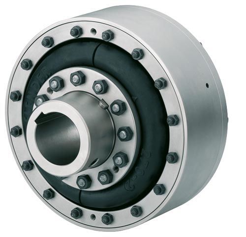
ELPEX couplings are highly torsionally flexible and free of torsional backlash. Because of their low torsional stiffness and damping capacity, ELPEX couplings are especially suitable for coupling machines with a very non uniform torque pattern. ELPEX couplings are also suitable for connecting machines with high shaft misalignment.
Standard ELPEX coupling types are designed as shaft-shaft connections or flange-shaft connections. Application-related types can be implemented on request.
Область применения
The ELPEX coupling is available in 9 sizes with a nominal torque of between 1600 Nm and 90000 Nm. The coupling is suitable for ambient temperatures of between –40 °C and +80 °C.
The ELPEX coupling is frequently used for high-quality drives which have to guarantee very long service life in harsh operating conditions. Examples of applications are mill drives in the cement industry, marine main and secondary drives or drives on large excavators powered by an electric motor or diesel engine.
Дизайн
Design and function
The ELPEX coupling's transmission characteristic is determined essentially by the flexible rings. The flexible rings are manufactured from a natural rubber mixture with a multiply fabric lining. The flexible rings are split so that they can be changed without having to move the coupled machines.
The flexible rings are fastened to the hub with a clamping ring and to the outer flange with a clamping ring, using pins and bolts.
On the type EFG, the outer flange is designed with connection dimensions for connection to e.g. a diesel engine flywheel. On ENG types, the outer flange is fitted to a second hub part, which then enables the shaft-shaft connection.
Materials:
Type
Cast iron
Steel
Hub part 1
Grey cast iron
EN-GJL-250Steel
Hub part 2
Steel
Steel
Retaining ring, outer ENG, ENGS
Grey cast iron
EN-GJL-250Steel
Outer flange EFG, EFGS
Grey cast iron
EN-GJL-250Steel
Flexible ring materials:
Material/description
Hardness
Identification
Ambient temperature
Natural rubber
70 ShoreA
Size - 2
–40 °C to +80 °C
ELPEX coupling types
Type
Description
ENG
Coupling as shaft-shaft connection
EFG
Coupling as flange-shaft connection
ENGS
as ENG with fail-safe device
EFGS
as EFG with fail-safe device
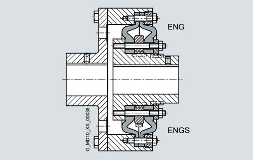
Types ENG/ENGS
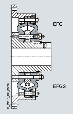
Types EFG/EFGS
Further application-specific coupling types are available.
Dimension sheets for and information on these are available on request. The following versions have already been implemented a number of times:- ELPEX coupling with brake drum, brake disk or flywheel mass
- ELPEX coupling with axial backlash limiter
- ELPEX coupling with adapter
- ELPEX coupling in combination with a safety slip clutch
- ELPEX coupling for engaging/disengaging during standstill
- ELPEX coupling as part of a coupling combination
Fail-safe device of ELPEX coupling
Types ENGS and EFGS are provided with a fail-safe device. In normal operation the torsion angle of the flexible rings is smaller than the gap between the cams. In normal operation there is no metal-metal contact.
If the flexible rings fail, cams transmit the torque from the inner part and outer part. These enable the coupling to be used in emergency mode for a short time. This option is frequently required e.g. in the case of marine drives.

Fail-safe device
Конфигурация
The ELPEX coupling is especially suitable for rough operation. An application factor different from that in catalog section 3 is therefore sufficient for all applications. In the case of machines which excite torsional vibration, FLENDER urgently recommends carrying out a torsional vibration calculation or measuring the coupling load occurring in the drive.
Coupling selection
Coupling load in continuous operation
The operating principles of the driving and driven machines are divided into categories and the application factor FB derived from these in accordance with DIN 3990-1.
Application factor FB
Torque characteristic of the driven machine
Torque characteristic of the driving machine
uniform with moderate shock loads
non uniform
very rough
Electric motors, hydraulic motors, gas and water turbines
1.0
1.3
1.4
Internal combustion engines
1.3
1.4
1.6
Examples of torque characteristic in driven machines:
- uniform with moderate shock loads: generators, fans, blowers
- non uniform: reciprocating compressors, mixers,
conveyor systems - very rough: crushers, excavators, presses, mills
Temperature factor FT
Temperature Ta on the coupling
Coupling
Elastomer material
–40 °C to –30 °C
–30 °C to +50 °C
to 60 °C
to 70 °C
to 80 °C
ELPEX
NR
1.1
1.0
1.25
1.40
1.60
NR: Natural rubber mixture
Select size with: TKN ≥ TN · FB · FT
Coupling load at maximum and overload conditions
The maximum torque is the highest load acting on the coupling in normal operation.
Maximum torques at a frequency of up to 25 times an hour are permitted and must be lower than the maximum coupling torque. Examples of maximum torque conditions are: Starting operations, stopping operations or usual operating conditions with maximum load.TKmax ≥ Tmax · FT
Overload torques are maximum loads which occur only in combination with special, infrequent operating conditions. Examples of overload torque conditions are: Motor short circuit, emergency stop or blocking because of component breakage. Overload torques at a frequency of once a month are permitted and must be lower than the maximum overload torque of the coupling. The overload condition may last only a short while, i.e. fractions of a second.
TKOL ≥ TOL · FT
Coupling load due to dynamic torque load
Applying the frequency factor FF, the dynamic torque load must be lower than the coupling fatigue torque.
Dynamic torque load
TKW ≥ TW · FT · FF · 0.6 / (FB – 1.0)Frequency of the dynamic torque load
ferr ≤10 Hz frequency factor FF = 1.0Frequency of the dynamic torque load
ferr >10 Hz frequency factor FF = √(ferr / 10 Hz)Checking the maximum speed:
The following must apply to all load situations: nKmax ≥ nmax
Checking permitted shaft misalignment and restorative forces
For all load situations the actual shaft misalignment must be less than the permitted shaft misalignment.
Checking bore diameter, mounting geometry and coupling design
The check must be made on the basis of the dimension tables. On request, couplings with adapted geometry can be provided.
Checking shaft-hub connection
Please refer to catalog section 3 for instructions.
Checking temperature and chemically aggressive environment
The permitted coupling temperature is specified in the Temperature Factor FT table. In the case of chemically aggressive environments, please consult the manufacturer.
Особенности
The ELPEX coupling is suitable for horizontal and vertical mounting positions or mounting at any required angle. The coupling parts can be arranged as required on the shafts to be connected.
The split flexible rings can be changed without having to move the coupled machines.
The flexible rings are mounted without backlash and give the coupling progressive torsional stiffness, i.e. torsional stiffness increases in proportion to coupling load.
The ELPEX coupling is especially suitable for reversing operation or operation with changing directions of load.
The coupling is delivered preassembled. The flexible rings are completely assembled. On the type ENG, the coupling halves have to be bolted together after the hub has been mounted. On the type EFG, after mounting the coupling hub, only the outer flange has to be connected to the machine.
Outer flanges with different connection dimensions are available for the type EFG.
If the flexible rings are irreparably damaged or worn, the metal parts can rotate freely against one another, they are not in contact with one another.
Технические данные
Power ratings
Size
Rated torque
Maximum torque
Overload torque
Fatigue torque
Dynamic torsional stiffness for 100 % capacity utilization
Stiffness
Permitted shaft misalignment at speed
n = 1500 rpmAxial
Radial
Axial
Radial
Angle
TKN
TKmax
TKOL
TKW
CTdyn
Ca
Cr
ΔKa
ΔKr
ΔKw
Nm
Nm
Nm
Nm
kNm/rad
N/mm
N/mm
mm
mm
Degree
270
1600
4800
6400
640
22.0
660
770
2.2
2.2
0.2
320
2800
8400
11200
1120
38.0
780
910
2.6
2.6
0.2
375
4500
13500
18000
1800
63.0
970
1130
3
3
0.2
430
7100
21300
28400
2840
97.0
1160
1350
3.4
3.4
0.2
500
11200
33600
44800
4480
155
1410
1630
3.8
3.8
0.2
590
18000
54000
72000
7200
240
1710
1990
4.2
4.2
0.2
690
28000
84000
112000
11200
365
2060
2390
4.6
4.6
0.2
840
45000
135000
180000
18000
685
2570
2990
5
5
0.2
970
90000
270000
360000
36000
1100
3020
3510
5.5
5.5
0.2
The damping coefficient is Ψ = 1.1
Torsional stiffness
The dynamic torsional stiffness is load-dependent and increases in proportion to capacity utilization. The values specified in the selection table apply to a capacity utilization of 100 %. The following table shows the correction factors for different rated loads.
CTdyn = CTdyn 100 % · FKC
Capacity utilization TN / TKN
20 %
50 %
60 %
70 %
80 %
100 %
200 %
Correction factor FKC
0.3
0.56
0.65
0.74
0.82
1
1.9
Torsional stiffness also depends on the ambient temperature and the frequency and amplitude of the torsional vibration excitation. More precise torsional stiffness and damping parameters on request.
Permitted shaft misalignment
The permitted shaft misalignment depends on the operating speed. As the speed increases, lower shaft misalignment values are permitted. The following table shows the correction factors for different speeds.
The maximum speed for the respective coupling size must be noted!ΔKperm = ΔK1500 · FKV
Speed in rpm
500
1000
1500
3000
Correction factor FKV
1.6
1.25
1.0
0.70