
- Каталог оборудования Siemens
- Каталог продуктов Siemens Industry
- Приводная техника
- Преобразователи
- Двигатели переменного тока
- Generators
- Мотор-редукторы
- Flender Gear Units
- Couplings
- Technical information
- Selection of the coupling series
- Flexible couplings N-EUPEX and N-EUPEX DS series
- Flexible couplings BIPEX series
- Flexible couplings BIPEX series
- Flexible couplings N-BIPEX series
- Flexible couplings RUPEX series
- Highly flexible couplings ELPEX series
- Highly flexible couplings ELPEX-B series
- Torsionally rigid gear couplings ZAPEX ZW series
- Torsionally Rigid Gear Couplings - ZAPEX ZN Series
- Torsionally rigid all-steel couplings ARPEX series
- SIPEX and BIPEX-S Backlash-free Couplings
- Non-positively acting couplings FLUDEX
- Taper clamping bushes
- Инструментальное программное обеспечение
- Дополнительные компоненты
- Техника автоматизации
- Energy
- Автоматизация и безопасность зданий
- Низковольтная коммутационная техника
- Технология безопасности
- Системные решения и продукты для отраслей
- Сервис
- Приводная техника
Flexible couplings BIPEX series
- Информационные материалы
Информационные материалы

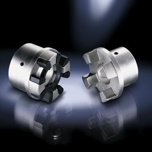
BIPEX couplings are torsionally flexible with low torsional backlash. They are outstanding for their particularly compact construction. BIPEX couplings link machine shafts.
BIPEX couplings are specially suited for electric motor drives which are well aligned and have uniform torque loads.
Область применения
The BIPEX coupling is available as a catalog standard in 13 sizes with rated torque of between 13.5 Nm and 3700 Nm.
The coupling is suitable for ambient temperatures of between –30 °C and +80 °C.BIPEX couplings are particularly suited for electric motor drives which have a uniform torque load and are well aligned. BIPEX couplings are frequently fitted and used in motor bell housings.
Дизайн
BIPEX couplings of types BWN, BWT and BNT each comprise two hub parts connected by a cam ring of elastomer material.

Type BWN

Type BWT

Type BNT
The couplings are inserted during fitting. The hubs are connected to the respective shafts via Taper clamping bushes or finished bores with parallel keyway connection.
BIPEX couplings are positive-locking and torsionally flexible thanks to the polyurethane cam ring. Shaft misalignment will result in deformation of the cam ring.Coupling materials:
Hubs: EN-GJL-250
Cam ring: PU 92 ShoreA –30 °C bis +80 °CTypes of BIPEX coupling
Type
Description
BWN
Coupling as a shaft-to-shaft connection with drilled and grooved hubs
BWT
Coupling as a shaft-shaft connection with Taper clamping bushes
BNT
Coupling as a shaft-shaft connection with drilled and grooved hubs and a Taper clamping bush
The coupling comprises the following:
- Cam ring
- 2 hub parts with identical cams. The hub parts are designed with a bore and keyway to DIN 6885 or with a taper bore for mounting a Taper clamping bush.
Fitting the clamping bush connects the hub firmly to the machine shaft. In the case of part 4 the Taper clamping bush is inserted from the machine housing side. If there is insufficient space, the Taper clamping bush cannot be fitted from this side. Besides space for fitting the Taper clamping bush, space for the fitting tool (offset screwdriver) must be taken into consideration. In the case of part 3 the Taper clamping bush is inserted from the shaft end face side. The hub must be fitted before the machines to be connected are pushed together.
Особенности
BIPEX couplings are suitable for mounting horizontally, vertically or at any desired angle. The coupling parts can be arranged as required on the shaft extensions to be connected.
The cam ring is mounted with low backlash and achieves progressive torsional stiffness, i.e. torsional stiffness increases in proportion to capacity utilization.
The BIPEX coupling is fail-safe, i.e. if the cam ring is worn, the cast cams of the coupling hub provide for emergency operation.
Технические данные
Power ratings
Size
Rated torque
Maximum torque
Overload torque
Fatigue torque
Maximum speed
Torsional stiffness at 50 % capacity utilization
Assembly
Gap dimensionPermissible shaft misalignment at speed n = 1500 rpm 1)
TKN
TKmax
TK0L
TKW
nmax
CTdyn 50 %
ΔS
ΔKa
ΔKr
ΔKw
Nm
Nm
Nm
rpm
Nm/rad
mm
mm
mm
Degrees
43
13.5
40.5
54
2.7
5000
1160
0.5
0.25
0.08
0.1
53
24
72
96
4.8
5000
2100
0.5
0.25
0.09
0.1
62
42
126
168
8.4
5000
3500
0.5
0.25
0.11
0.1
72
75
225
300
15
5000
6100
0.5
0.25
0.12
0.1
84
130
390
520
26
5000
9600
0.5
0.25
0.14
0.1
97
220
660
880
44
5000
15800
1.0
0.5
0.16
0.1
112
360
1080
1440
72
5000
23100
1.0
0.5
0.19
0.1
127
550
1650
2200
110
5000
37000
1.0
0.5
0.21
0.1
142
800
2400
3200
160
4900
57000
1.0
0.5
0.24
0.1
162
1250
3750
5000
250
4200
85000
1.0
0.5
0.27
0.1
182
1750
5250
7000
350
3800
127000
1.0
0.5
0.30
0.1
202
2650
7950
10600
530
3400
171000
1.0
0.5
0.34
0.1
227
3700
11100
14800
740
3000
285000
2.0
1.0
0.38
0.1
1) The maximum speed of the respective type must be noted. For further information on permissible shaft misalignment, please see the operating instructions.
Torsional stiffness and damping
The values stated in the above table apply to a capacity utilization of 50 %, an excitation amplitude of 10 % TKN with the frequency 10 Hz and an ambient temperature of 20 °C. Dynamic torsional stiffness is dependent on load and increases in proportion to capacity utilization. The following table shows the correction factors for different nominal loads.
CTdyn = CTdyn 50 % · FKC
Capacity utilization TN/TKN
20 %
40 %
50 %
60 %
70 %
80 %
100 %
Correction factor FKC
0.7
0.9
1.0
1.1
1.25
1.4
1.7
The damping coefficient is Ψ = 1.4
Furthermore, torsional stiffness and damping depend on the ambient temperature and the frequency and amplitude of the torsional vibration excitation. More precise torsional stiffness and damping parameters on request.
Permitted shaft misalignment
The permitted shaft misalignment depends on the operating speed. As the speed increases, lower shaft misalignment values are permitted. The following table shows the correction factors for different speeds.
The maximum speed for the respective coupling size and type must be observed!ΔKperm = ΔK1500 · FKV
Speed in rpm
500
1000
1500
3000
Correction factor FKV
1.20
1.10
1.0
0.70
The axial misalignment may occur dynamically at frequencies up to 10 Hz. For fitting, a maximum gap dimension of Smax = S + ΔS and a minimum gap dimension of Smin = S – ΔS are permitted.
Shaft misalignments ΔKa, ΔKr and ΔKw may occur simultaneously.