
- Каталог оборудования Siemens
- Каталог продуктов Siemens Industry
- Приводная техника
- Преобразователи
- Двигатели переменного тока
- Generators
- Мотор-редукторы
- Flender Gear Units
- Couplings
- Technical information
- Selection of the coupling series
- Flexible couplings N-EUPEX and N-EUPEX DS series
- Flexible couplings BIPEX series
- Flexible couplings N-BIPEX series
- Flexible couplings RUPEX series
- Highly flexible couplings ELPEX series
- Highly flexible couplings ELPEX-B series
- Torsionally rigid gear couplings ZAPEX ZW series
- Torsionally Rigid Gear Couplings - ZAPEX ZN Series
- Torsionally rigid all-steel couplings ARPEX series
- SIPEX and BIPEX-S Backlash-free Couplings
- Non-positively acting couplings FLUDEX
- Taper clamping bushes
- Инструментальное программное обеспечение
- Дополнительные компоненты
- Техника автоматизации
- Energy
- Автоматизация и безопасность зданий
- Низковольтная коммутационная техника
- Технология безопасности
- Системные решения и продукты для отраслей
- Сервис
- Приводная техника
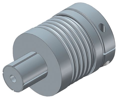
Torsionally Rigid Couplings - SIPEX Series
- Информационные материалы
Информационные материалы
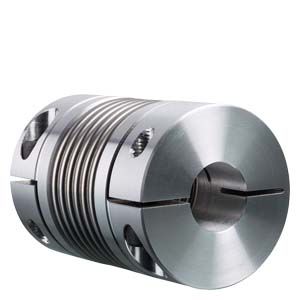
SIPEX couplings are torsionally rigid and backlash-free. They are characterized by their compact design and high power density. SIPEX couplings connect machine shafts and compensate for shaft misalignment that can occur during assembly or operation.
SIPEX couplings are suitable for all drive applications which require a coupling that offers positioning accuracy as well as a reliable, wear- and maintenance-free torque transmission.
Область применения
SIPEX couplings are available in 19 sizes within the standard catalog range, 7 of which are miniature versions and the other 12 standard designs. Rated torques range from 0.1 to 5000 Nm. The coupling is suitable for ambient temperatures of between -30 °C to +120 °C
Couplings manufactured by alternative methods are available for higher ambient temperatures up to +250 °C.
SIPEX couplings from the standard range are especially suitable for application in highly dynamic drives such as, for example, linear axes in machine tools, packaging machines or printing presses, or generally for automation technology.
SIPEX couplings from the miniature range are designed for use in combination with rotary encoders, stepper motors or tachometers.
Дизайн
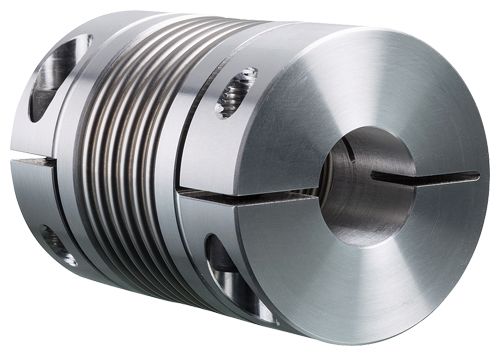
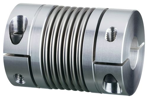
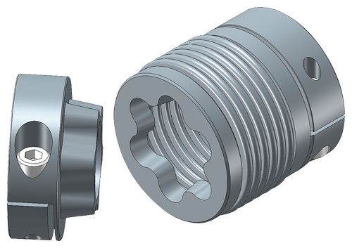
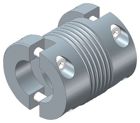
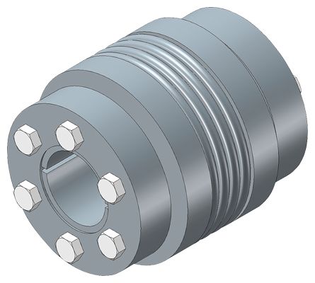
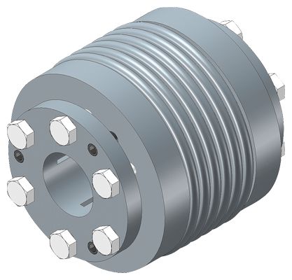
SIPEX couplings consist of two hub parts that are connected by means of bellows made of high-strength stainless steel.
The hubs can be coupled to the shafts by many different methods including set screws, key joint, slotted clamping hubs, half-shell hubs, clamping hubs or expanding hubs.
Thanks to their metal bellows, SIPEX couplings are torsionally rigid, but flexible. Misalignment between the connected shafts deforms the metal bellows.
Coupling materials:
Depending on the coupling version, hubs are made of aluminum (N, G, H) or steel (K, I), but stainless-steel variants are also optionally available.
All the metal bellows are made of stainless steel and are available as single-wall or multiple-wall devices depending on size and application. Metal bellows come in various standard lengths.
Metal bellows can be combined with different hub versions to create a complete unit. Once the hubs have been joined to metal bellows, they cannot be dismantled again.
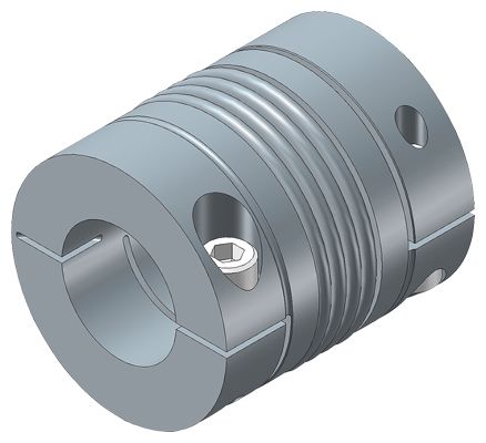
Hub versions:
N: Hub with set screws
G: Slotted clamping hub
H: Half-shell clamping hub
K: Clamping hub with external taper
I: Clamping hub with internal taper
S: Expanding hubHubs are supplied as standard with bore tolerance H7 and without keyway.
Versions N, G and H are optionally available with keyway in accordance with DIN 6885-1.
The fitting tolerance of the coupled shaft ends should be g6 or h7.
Versions of SIPEX couplings:
Type
Description
SNN
Hub with set screw on both sides
SGG
Slotted clamping hub on both sides
SGG-A
Slotted clamping hub - for axial plug-in
SHH
Half-shell clamping hub on both sides
SKK
Clamping hub with external taper on both sides
SGS
Hub 1: Slotted/Hub 2: Expanding hub
SHH-W
Drive shaft with half-shell clamping hubs
SII
Clamping hubs with internal taper on both sides
Hub variants

Set screw
Clamping hub
Axial plug-in
Half-shell clamping hub
External taper
Internal taper
Expanding hub
Особенности
SIPEX couplings are suitable for mounting horizontally, vertically or in any desired position. The coupling parts can be arranged as required on the shaft ends to be connected.
The metal bellows are very torsional-resistant and combined with different clamping connections they ensure an absolutely angle-preserving torque transmission between the connected shafts. The moment of inertia is low.
SIPEX couplings compensate axial, radial and angular shaft misalignment with only low restoring forces. SIPEX couplings are wear-free within their technical limits and therefore offer an unlimited service life.
Технические данные
Coupling dimensioning
Dimensioning according to torque
It must be ensured that the coupling is capable of safely transferring peak torques that regularly occur at the drive or load end. The service factor is provided in order to describe the deviation between the real coupling load and ideal load conditions:
TKN ≥ TAS × FB or TLS × FB
Torque characteristic of drive
Service factor FB
uniform
1.5
nonuniform
2
rough
2.5 - 4
Servomotors (machine tools)
1.5 - 2
Dimensioning according to acceleration torques
The correct coupling size can be calculated more accurately on the basis of acceleration or deceleration torques because the peak torque at the coupling is reduced by the ratio between the moments of inertia on the drive and load ends:
TKN ≥ TS × FB
TS = TAS × JL : (JA + JL) or TS = TLS × JL : (JA + JL)
Checking the maximum torsion angle
If the application requires a maximum torsion angle of the coupling, the selected coupling size must be checked to ensure that it is sufficiently torsionally rigid for the application in question:
φ = (180 : π) × (TS : CTdyn)
Checking the maximum speed
For all load situations nKmax > nmax
Checking the permitted shaft misalignment
The actual shaft misalignment must be less than the permitted shaft misalignment for all load situations.
Checking the shaft-hub connection
In the case of clamping connections without feather key, it must be ensured that the transmissible torque of the hub connection is greater than the peak torque at the coupling.
Formula symbols
Key to formula symbols
Name
Formula symbol
Unit
Explanation
Rated coupling torque
TKN
Nm
Torque which can be transmitted as static torque by the coupling over the period of use.
Coupling overload torque
TKOL
Nm
Torque which can be transmitted very rarely as maximum torque by the coupling.
Peak torque at drive end
TAS
Nm
Peak torque during non-periodic torque surges at drive end
Peak torque at load end
TLS
Nm
Peak torque during non-periodic torque surges at load end
Peak torque
TS
Nm
Peak torque at the coupling
Service factor
FB
Factor that expresses the real coupling load as a ratio of the nominal coupling load
Moment of inertia of drive end
JA
kgm2
Sum of the moments of inertia at the drive end referred to the coupling speed
Moment of inertia of load end
JL
kgm2
Sum of the moments of inertia at the load end referred to the coupling speed
Torsion angle
φ
°
Torsion angle of the coupling under torsional load
Torsional stiffness, dynamic
CTdyn
Nm/rad
Dynamic torsional stiffness of the coupling
Axial stiffness
Ca
N/mm
Axial stiffness of the coupling
Radial stiffness
Cr
N/mm
Radial stiffness of the coupling
Rated speed
nN
rpm
Coupling speed
Maximum coupling speed
nKmax
rpm
Maximum permissible coupling speed
Axial misalignment
ΔKa
mm
Axial misalignment of the coupling halves
Radial misalignment
ΔKr
mm
Radial misalignment of the coupling halves
Angular misalignment
ΔKw
°
Angular misalignment of the coupling halves
Technical specifications
Power ratings of the miniature series
Size
Rated torque
Maximum torque
Maximum speed
Torsional stiffness
Stiffness
Permitted shaft misalignment
Radial
Axial
TKN
TKOL
nKmax
CTdyn
Cr
Ca
ΔKa
ΔKr
ΔKw
Nm
Nm
rpm
Nm/rad
N/mm
N/mm
mm
mm
grad
1
0.1
0.15
15000
65
10
14
0.2
0.1
1.5
5
0.5
0.75
15000
258
128
18
0.2
0.1
1.5
195
54
13
0.3
0.2
1.5
160
26
11
0.4
0.2
2
10
1
1.5
15000
510
187
36
0.2
0.1
1.5
380
82
27
0.3
0.2
1.5
308
42
22
0.4
0.2
2
15
1.5
2.25
15000
750
139
23
0.3
0.1
1.5
700
81
12
0.4
0.2
2
20
2
3
15000
1510
147
18
0.3
0.2
1.5
1300
96
14
0.4
0.2
1.5
1040
46
9
0.5
0.3
2
45
4.5
6.75
15000
6480
444
47
0.3
0.1
1.5
4100
108
29
0.5
0.2
2
100
10
15
15000
8080
361
46
0.4
0.2
1.5
6750
193
34
0.6
0.3
2
Power ratings of the standard series
Size
Rated torque
Maximum torque
Maximum speed
Torsional stiffness
Stiffness
Permitted shaft misalignment
Radial
Axial
TKN
TKOL
nKmax
CTdyn
Cr
Ca
ΔKa
ΔKr
ΔKw
Nm
Nm
rpm
Nm/rad
N/mm
N/mm
mm
mm
grad
18
18
27
12800
19
200
50
0.5
0.2
1.5
17
85
40
0.5
0.2
2.0
30
30
45
10300
36
720
50
0.5
0.2
1.5
26
220
30
0.8
0.2
2.0
60
60
90
8700
75
1100
90
0.5
0.2
1.5
50
330
55
0.8
0.2
2.0
80
80
120
6900
128
1200
80
0.5
0.2
1.5
75
400
55
0.7
0.2
2.0
150
150
225
6900
155
2000
150
0.5
0.2
1.5
102
600
85
0.6
0.2
2.0
200
200
300
6400
175
2500
150
0.5
0.2
1.5
120
450
85
0.7
0.2
2.0
300
300
450
6000
502
6300
280
0.5
0.2
1.5
282
1500
85
0.7
0.2
2.0
500
500
750
5000
690
8800
100
0.5
0.2
1.5
315
1000
85
0.8
0.2
2.0
800
800
1200
3700
760
510
190
0.8
0.2
1.8
1400
1400
2100
3700
1300
710
280
0.8
0.2
1.8
3000
3000
4500
2800
2800
8060
880
0.8
0.2
1.5
5000
5000
7500
2800
4800
9190
740
0.8
0.2
1.5
Permitted shaft misalignment
The permitted shaft misalignments ΔKa, ΔKr und ΔKw are maximum values and must not occur simultaneously. The following formula can be used to roughly calculate whether combinations of misalignments are permissible:
(ΔKract : ΔKr) + (ΔKaact : ΔKa) + (ΔKwact : ΔKw) < 1
The different torsional stiffness values apply to the various lengths of metal bellows of the relevant SIPEX type.