
- Каталог оборудования Siemens
- Каталог продуктов Siemens Industry
- Приводная техника
- Техника автоматизации
- Energy
- Автоматизация и безопасность зданий
- Низковольтная коммутационная техника
- Технология безопасности
- Системные решения и продукты для отраслей
- Автомобильная промышленность
- Биотопливо
- Химическая промышленность
- Пищевая промышленность
- Производственные машины
- Packaging machines
- Printing presses
- Textile machines
- Converting
- Metal forming technology
- Handling systems
- Непрерывное преобразование листового материала - Converting
- Печать
- Манипуляторы
- Пластик
- Текстиль
- Обработка металлов давлением
- Упаковка
- Компоненты автоматизации для станков
- SINUMERIK 808 with SINAMICS V60/V70
- SINUMERIK 828 with SINAMICS S120
- Introduction SINUMERIK 828 with SINAMICS S120
- Обзор функций SINUMERIK 828D с SINAMICS S120 Combi
- SINUMERIK CNC controls
- SINAMICS S120 drive system
- SINAMICS S120 Combi Power Modules
- External fan module, reinforcement plates
- Line reactors
- Line filters
- SINAMICS S120 booksize compact format
- SINAMICS S120 in booksize format
- Smart Line Modules in booksize format
- Smart Line Modules in booksize format
- Line reactors for Smart Line Modules
- Line filters for Smart Line Modules
- Recommended line-side components for Smart Line Modules
- Active Line Modules in booksize format
- Active Interface Modules in booksize format
- Line filters
- Basic Line Filters for Active Line Modules
- Recommended line-side components for Active Line Modules
- Basic Line Modules in booksize format
- Line reactors for Basic Line Modules
- Line filters for Basic Line Modules
- Recommended line-side components for Basic Line Modules
- Single Motor Modules in booksize format
- Double Motor Modules in booksize formats
- Series motor reactors
- Braking Module in booksize format
- Braking resistors for booksize format
- Capacitor Module in booksize format
- Control Supply Module in booksize format
- DC link adapters for booksize and booksize compact formats
- DMC20 DRIVE-CLiQ Hub Module
- DME20 DRIVE-CLiQ Hub Module
- TM54F Terminal Module
- SMC20 Sensor Module Cabinet-Mounted
- SMC30 Sensor Module Cabinet-Mounted
- SMC40 Sensor Module Cabinet-Mounted
- SME120/SME125 Sensor Modules External
- SIMOTICS motors
- Motion Control Encoder measuring systems
- MOTION-CONNECT connection systems
- Services and training
- SINUMERIK Solution Partners
- Certificates of suitability (approvals)
- ЧПУ SINUMERIK 828
- Glossary SINAMICS S120 drive system
- List of abbreviations
- SINUMERIK 840 with SINAMICS S120
- Приводные применения
- Горная и металлургическая промышленность
- Нефтегазовая промышленность
- Фармацевтическая промышленность
- Бумажная промышленность
- Солнечная энергетика
- Транспорт, инфраструктура, логистика
- Вода и водоподготовка
- Сбыт электроэнергии
- Возобновляемые источники энергии
- Отраслевые решения
- Отраслевые продукты
- Сервис

Smart Line Modules in booksize format
- Заказные данные (10)
- Аксессуары (10)
- Информационные материалы
Информационные материалы

Smart Line Modules are stall-protected, line-commutated infeed/regenerative feedback units (diode bridge for incoming supply; stall-protected, line-commutated regenerative feedback via IGBTs) with 100 % continuous regenerative feedback power. The regenerative feedback capability of the modules can be deactivated by means of a digital input (Smart Line Modules 5 kW and 10 kW) or by means of parameterization (Smart Line Modules 16 kW, 36 kW and 55 kW). Smart Line Modules are designed for connection to grounded TN/TT systems and non-grounded IT systems.
The DC link is pre-charged via integrated precharging resistors.
The associated line reactor is required for operating a Smart Line Module.
Дизайн
The Smart Line Modules in booksize format feature the following connections and interfaces as standard:
- 1 power connection via screw-type terminals
- 1 connection for the 24 V DC electronics power supply via the 24 V terminal adapter included in the scope of supply
- 1 DC link connection via integrated DC link busbars
- 2 PE (protective earth) connections
- 2 digital inputs
(only for Smart Line Modules 5 kW (5 hp) and 10 kW (10 hp)) - 1 digital output
(only for Smart Line Modules 5 kW (5 hp) and 10 kW (10 hp)) - 3 DRIVE‑CLiQ sockets
(only for Smart Line Modules 16 kW (18 hp), 36 kW (40 hp) and 55 kW (60 hp)) - 1 temperature sensor input for KTY84‑130, Pt1000 or PTC (only for Smart Line Modules 16 kW (18 hp), 36 kW (40 hp) and 55 kW (60 hp), Pt1000 can be used from firmware V4.7 HF17)
The status of the Smart Line Modules is indicated via two multi-color LEDs.
The signal cable shield can be connected to the Line Module by means of a shield connection terminal, e.g. Weidmüller type KLBÜ 3-8 SC.
The scope of supply of the Smart Line Modules includes:
- DRIVE‑CLiQ cable for connecting the module to the adjacent Control Unit on the left with the drive control, length 0.11 m (4.33 in)
(only for Smart Line Modules 16 kW (18 hp), 36 kW (40 hp) and 55 kW (60 hp)) - 2 blanking plugs for closing unused DRIVE-CLiQ sockets
(only for Smart Line Modules 16 kW (18 hp), 36 kW (40 hp) and 55 kW (60 hp)) - DRIVE‑CLiQ cable (length depends on Smart Line Module width) for connection to the adjacent Motor Module, length = width of Smart Line Module + 0.11 m (4.33 in)
- Jumper for connecting the 24 V DC busbar to the adjacent Motor Module
- 24 V terminal adapter (X24)
- Connector X21 for digital inputs and outputs
- Connector X22 for digital inputs and outputs
(only for Smart Line Modules 5 kW (5 hp) and 10 kW (10 hp)) - Connector X1 for line connection
(only for Smart Line Modules 5 kW (5 hp) and 10 kW (10 hp)) - 1 set of warning labels in 30 languages
Характеристика
Overload capability

Duty cycle with previous load

S6 duty cycle with previous load

S6 duty cycle with previous load
Derating characteristics
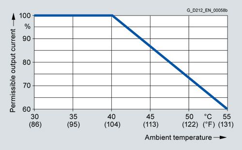
Output power as a function of ambient temperature

Output power as a function of total cable length
Installation altitude
- >1000 ... 4000 m (3281 ... 13124 ft) above sea level
- Reduction of the output current by 10 % per 1000 m (3281 ft), or
- Reduction of the ambient temperature by 5 °C (41 °F) per 1000 m (3281 ft)
- >2000 ... 4000 m (6562 ... 13124 ft) above sea level
- Operation on line supply systems with grounded neutral point, or
- Operation with an isolating transformer with secondary grounded neutral point
Интеграция

Connection example of 5 kW and 10 kW Smart Line Modules in booksize format

Connection example of 16 kW, 36 kW and 55 kW Smart Line Modules in booksize format
Технические данные
Smart Line Module in booksize format
6SL313...
Line voltage
(up to 2000 m (6562 ft) above sea level)
380 ... 480 V 3 AC ±10 % (in operation -15 % <1 min)
Line frequency
47 ... 63 Hz
SCCR (short-circuit current rating)
65 kA in conjunction with the recommended Class J fuse, or circuit breaker according to UL489 / CSA 22.2 No. 5-02
see recommended line-side components
Line power factor
at rated power
- Fundamental power factor (cos φ1)
>0.96
- Total (λ)
0.65 ... 0.9
Overvoltage category
according to EN 60664‑1
Class III
DC link voltage, approx.
1.35 × line voltage1)
Electronics power supply
24 V DC -15 %/+20 %
Radio interference suppression
- Standard
No radio interference suppression
- With line filter
Category C2 to EN 61800‑3
Total cable length up to 350 m (1148 ft) (shielded)Type of cooling
Internal air cooling (power units with increased air cooling using an integrated fan)
Permissible ambient and coolant temperature (air)
during operation for line-side components, Line Modules and Motor Modules
0 ... 40 °C (32 ... 104 °F) without derating,
> 40 ... 55 °C (104 ... 131 °F), see derating characteristicsInstallation altitude
Up to 1000 m (3281 ft) above sea level without derating,
> 1000 ... 4000 m (3281 ... 13124 ft) above sea level, see derating characteristicsDeclarations of conformity
CE (Low Voltage and EMC Directives)
Certificate of suitability
cULus
1) The DC link voltage is maintained at the mean value of the rectified line voltage. For further information, see section Tools and configuring.
Line voltage 380 ... 480 V 3 AC
Smart Line Module in booksize format
Internal air cooling
6SL3130-6AE15-0AB1
6SL3130-6AE21-0AB1
6SL3130-6TE21-6AA4
6SL3130-6TE23-6AA3
6SL3130-6TE25-5AA3
Infeed/regenerative feedback power
- Rated power Prated
- At 380 V 3 AC
kW
5
10
16
36
55
- At 460 V 3 AC 3)
(hp)
(5)
(10)
(18)
(40)
(60)
- For S6 duty (40%) PS6
kW
6.5
13
21
47
71
- Pmax
kW
10
20
35
70
91
DC link current
- At 540/600 V DC
A
9.3/8.3
18.5/16.6
30/27
67/60
105/92
- For S6 duty (40 %)
A
11
22
35
79
138
- Maximum
A
16.6
33.2
59
118
178
Input current
- Rated current
at 380/400/480 V 3 AC
A
8.6/8.1/6.7
17/16.2/12.8
29/27.5/24.5
62/59/51
94/90/77
- For S6 duty (40 %) at 400 V
A
10.6
21.1
35
76
106
- At 400 V max.
A
15.7
31.2
57.5
112
130
Current requirement
24 V DC electronics power supply, max.
A
0.8
0.9
0.95
1.5
1.9
Current carrying capacity
- 24 V DC busbars
A
20
20
20
20
20
- DC link busbars
A
100
100
100
200
200
DC link capacitance
- Smart Line Module
μF
220
330
710
1410
1880
- Drive line-up, max.
μF
6000
6000
20000
20000
20000
Power loss 1)
kW
0.08
0.14
0.19
0.406
0.666
Cooling air requirement
m3/s (ft3/s)
0.008 (0.3)
0.008 (0.3)
0.016 (0.6)
0.031 (1.1)
0.044 (1.5)
Sound pressure level
LpA (1 m)
dB
<60
<60
<60
<65
<60
Line connection
U1, V1, W1
Screw-type terminals (X1)
Screw-type terminals (X1)
Screw-type terminals (X1)
M6 screw studs (X1)
M6 screw studs (X1)
- Conductor cross-section
mm2
2.5 ... 6
2.5 ... 6
2.5 ... 10
2.5 ... 50
2.5 ... 95
Shield connection
Shield connection plate integrated into the connector
Shield connection plate integrated into the connector
Shield connection plate integrated into the connector
See Accessories
See Accessories
PE connection
M5 screw
M5 screw
M5 screw
M6 screw
M6 screw
Cable length, max.
(total of all motor power cables
and DC link)- Shielded
m (ft)
350 (1148)
350 (1148)
630 (2067)
630 (2067)
1000 (3281)
- Unshielded
m (ft)
560 (1837)
560 (1837)
850 (2789)
850 (2789)
1500 (4922)
Degree of protection
IP20
IP20
IP20
IP20
IP20
Dimensions
- Width
mm (in)
50 (1.97)
50 (1.97)
100 (3.94)
150 (5.91)
200 (7.87)
- Height
mm (in)
380 (14.96)
380 (14.96)
380 (14.96)
380 (14.96)
380 (14.96)
- Depth
mm (in)
270 (10.63)
270 (10.63)
270 (10.63)
270 (10.63)
270 (10.63)
Weight, approx.
kg (lb)
4.7 (10.4)
4.8 (10.6)
7 (15.4)
10 (22.0)
17 (37.5)
1) Power loss of Smart Line Module at rated output including losses of 24 V DC electronics power supply.
2) Power loss of the power electronics + power loss of the 24 V electronics.
3) Nominal HP ratings are provided for ease of assigning components only. The Line Module outputs are dependent on the Motor Module loading and are to be dimensioned accordingly.