
- Каталог оборудования Siemens
- Каталог продуктов Siemens Industry
- Приводная техника
- Техника автоматизации
- Energy
- Автоматизация и безопасность зданий
- Низковольтная коммутационная техника
- Технология безопасности
- Системные решения и продукты для отраслей
- Автомобильная промышленность
- Биотопливо
- Химическая промышленность
- Пищевая промышленность
- Производственные машины
- Packaging machines
- Printing presses
- Textile machines
- Converting
- Metal forming technology
- Handling systems
- Непрерывное преобразование листового материала - Converting
- Печать
- Манипуляторы
- Пластик
- Текстиль
- Обработка металлов давлением
- Упаковка
- Компоненты автоматизации для станков
- SINUMERIK 808 with SINAMICS V60/V70
- SINUMERIK 828 with SINAMICS S120
- Introduction SINUMERIK 828 with SINAMICS S120
- Обзор функций SINUMERIK 828D с SINAMICS S120 Combi
- SINUMERIK CNC controls
- SINAMICS S120 drive system
- SINAMICS S120 Combi Power Modules
- External fan module, reinforcement plates
- Line reactors
- Line filters
- SINAMICS S120 booksize compact format
- SINAMICS S120 in booksize format
- DMC20 DRIVE-CLiQ Hub Module
- DME20 DRIVE-CLiQ Hub Module
- TM54F Terminal Module
- TM54F Terminal Module
- SMC20 Sensor Module Cabinet-Mounted
- SMC30 Sensor Module Cabinet-Mounted
- SMC40 Sensor Module Cabinet-Mounted
- SME120/SME125 Sensor Modules External
- SIMOTICS motors
- Motion Control Encoder measuring systems
- MOTION-CONNECT connection systems
- Services and training
- SINUMERIK Solution Partners
- Certificates of suitability (approvals)
- ЧПУ SINUMERIK 828
- Glossary SINAMICS S120 drive system
- List of abbreviations
- SINUMERIK 840 with SINAMICS S120
- Приводные применения
- Горная и металлургическая промышленность
- Нефтегазовая промышленность
- Фармацевтическая промышленность
- Бумажная промышленность
- Солнечная энергетика
- Транспорт, инфраструктура, логистика
- Вода и водоподготовка
- Сбыт электроэнергии
- Возобновляемые источники энергии
- Отраслевые решения
- Отраслевые продукты
- Сервис
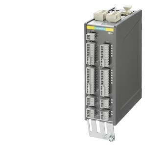
TM54F Terminal Module
- Заказные данные (1)
- Аксессуары (1)
- Информационные материалы
Информационные материалы

TM54F Terminal Module
The TM54F Terminal Module is a dual-processor I/O interface with four fail-safe digital outputs and ten fail-safe digital inputs for utilization of the Safety Integrated functions of the SINAMICS S120 drive system via external actuators and sensors.
Every available safety function integrated in the drive can be controlled via the fail-safe digital inputs on the TM54F Terminal Module. In the event that the parameterized safety functions of several drives operated together on a Control Unit are to be executed together, then these drives can be grouped in the TM54F Terminal Module. The advantage of this approach is that only one fail-safe digital input needs to be connected for these drives.
The fail-safe digital inputs and outputs have two channels and are redundantly configured with an internal data cross-check using the two processors. A fail-safe digital output consists of one P‑switching and one M‑switching output as well as one digital input to read back the switching state. A fail-safe digital input consists of two digital inputs.
Safety sensors can be connected over two switchable 24 V sensor supplies and can be evaluated over the fail-safe digital inputs. The switchable 24 V sensor supply ensures that the fail-safe digital inputs can be dynamized to detect dormant errors (this dynamization is used to check the shutdown paths). An unswitchable 24 V sensor supply is additionally provided by the TM54F Terminal Module for connecting undynamizable safety sensors.
The TM54F Terminal Module must be directly connected to a Control Unit via a DRIVE‑CLiQ cable. Only one TM54F Terminal Module can be assigned to each Control Unit. It is not permissible to make the TM54F connection via another DRIVE‑CLiQ device, e.g. a Motor Module or a Line Module.
Дизайн
The following are located on the TM54F Terminal Module:
- 4 fail-safe digital outputs
- 10 fail-safe digital inputs
- 4 LEDs, single color for indicating the status of the read back channel of the fail-safe digital outputs
- 4 LEDs, dual-color for indicating the status of the fail-safe digital outputs
- 20 LEDs, dual-color for indicating the status of the fail-safe digital inputs
- 3 LEDs, single color for indicating the status of the 24 V sensor supplies
- 2 DRIVE-CLiQ sockets
- 2 connections for 24 V sensor supply, switchable
- 1 connection for 24 V sensor supply, not switchable
- 1 connection for the electronics power supply via the 24 V DC power supply connector
- 1 connection for the 24 V power supply to digital outputs and sensors
- 1 PE (protective earth) connection
The status of the TM54F Terminal Module is indicated via a multi-color LED.
The TM54F Terminal Module can be snapped onto a TH 35 standard mounting rail in accordance with EN 60715 (IEC 60715).
The signal cable shield can be attached to the TM54F Terminal Module via a shield connection terminal, e.g. type SK8 supplied by Phoenix Contact or type KLBÜ CO 1 supplied by Weidmüller. The shield connection terminal must not be used as a strain relief mechanism.
Pins for connector coding are included in the TM54F Terminal Module scope of supply.
Интеграция
The TM54F Terminal Module can communicate via DRIVE‑CLiQ with the following Control Units.
- CU310‑2 Control Unit
- CU320‑2 Control Unit
- SINUMERIK Control Unit
- SIMOTION D Control Unit or Controller Extension

Connection example of TM54F Terminal Module
Технические данные
TM54F Terminal Module
6SL3055-0AA00-3BA0
Current requirement
(X524 at 24 V DC) without DRIVE-CLiQ supply
0.2 A
- Conductor cross-section, max.
2.5 mm2
- Fuse protection, max.
20 A
Max. current requirement ext. 24 V
for supplying the digital outputs and 24 V sensor supply (X514 at 24 V DC)
4 A
- Conductor cross-section, max.
2.5 mm2
- Fuse protection, max.
20 A
I/O
- Number of fail-safe digital inputs
10
- Number of fail-safe digital outputs
4
- 24 V sensor supply
3, of which 2 can be temporarily shut down using an internal test routine for dynamizing fail-safe digital inputs, current carrying capacity 0.5 A each
- Cables and connections
Plug-in screw-type terminals
- Conductor cross-section, max.
1.5 mm2
Digital inputs
in accordance with IEC 61131‑2 Type 1, with galvanic isolation
- Voltage
-3 ... +30 V
- Low level
(an open digital input is interpreted as "low")
-3 ... +5 V
- High level
15 ... 30 V
- Current consumption at 24 V DC, typ.
>3.2 mA
- Delay time of digital inputs, approx. 1)
- L → H, typ.
30 μs
- H → L, typ.
60 μs
- Safe state
Low level (for inputs that can be inverted: without inversion)
Digital outputs
sustained-short-circuit-proof
- Voltage
24 V DC
- Load current per fail-safe digital output, max. 2)
0.5 A
- Delay times (resistive load) 1)
- L → H, typ.
300 μs
- H → L, typ.
350 μs
- Safe state
Output switched off
Scanning cycle tSI
for fail-safe digital inputs or fail-safe digital outputs
4 ... 25 ms (adjustable)
Power loss, max.
At 24 V
4.5 W
PE connection
M4 screw
Dimensions
- Width
50 mm (1.97 in)
- Height
151 mm (5.94 in)
- Depth
110 mm (4.33 in)
Weight, approx.
0.9 kg (1.98 lb)
Certificate of suitability
cULus
Safety Integrated
Acc. to IEC 61508 SIL 2
and EN ISO 13849‑1 PL d and Category 31) The specified delay times refer to the hardware. The actual reaction time depends on the time slot in which the digital input/output is processed.
2) The total current of all fail-safe digital outputs must not exceed 5.33 A.