
- Каталог оборудования Siemens
- Каталог продуктов Siemens Industry
- Приводная техника
- Преобразователи
- Стандартные преобразователи
- Общая информация о базовых преобразователях SINAMICS V
- Преобразователи частоты общего назначения SINAMICS G
- Высокопроизводительные преобразователи SINAMICS S
- Сервопреобразователь SINAMICS S110
- SINAMICS S120
- SINAMICS S120M distributed servo drive
- SINAMICS S120 Combi
- SINAMICS S120 Chassis Format Units
- SINAMICS S120 Cabinet Modules
- SINAMICS S150 converter cabinet units
- MICROMASTER
- SIPLUS POSMO A
- SIMODRIVE POSMO
- LOHER DYNAVERT Drive System
- Преобразователи на среднее напряжение
- Преобразователи постоянного тока
- Стандартные преобразователи
- Двигатели переменного тока
- Generators
- Мотор-редукторы
- Flender Gear Units
- Couplings
- Инструментальное программное обеспечение
- Дополнительные компоненты
- Преобразователи
- Техника автоматизации
- Energy
- Автоматизация и безопасность зданий
- Низковольтная коммутационная техника
- Технология безопасности
- Системные решения и продукты для отраслей
- Сервис
- Приводная техника

Customer terminal block -X55
- Информационные материалы
Информационные материалы
Customer terminal block -X55 is the interface with the I/O devices and marshals a range of cabinet-internal signals to a central terminal block module mounted in the lower part of the cabinet.
It can be used for Motor Modules in the chassis format as well as together with options K90 (Control Unit CU320-2 DP) or K95 (Control Unit CU320-2 PN) for Basic Line Modules, Smart Line Modules, Active Line Modules and Booksize Cabinet Kits.
Дизайн
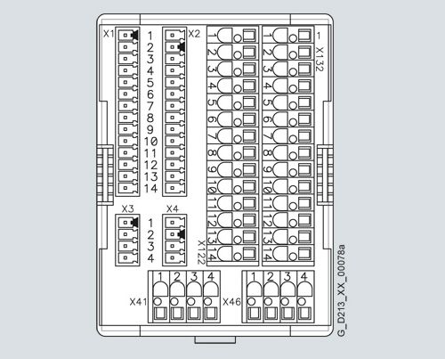
To connect signal cables on the customer side, terminal block -X55 includes terminals -X122, -X132, -X41 and -X46 (terminals -X1 to -X4 are used inside the cabinet and are not available). As a consequence, depending on the version (with/without option K90) the following digital inputs/outputs and/or signals are available:
The customer terminal strip -X55 includes:
Motor Modules in chassis format
Line Modules
Without
With
Without
With
CU320‑2 (K90/K95)
CU320‑2 (K90/K95)
-X122, -X132
12 digital inputs DI
–
✓
–
✓
8 bidirectional inputs/outputs (DI/DO)
–
✓
–
✓
-X41
Connection safety function Safe Torque Off / Safe Stop 1
✓
✓
– 1)
– 1)
Connection temperature sensor KTY84/PTC/Pt100
✓
✓
– 1)
– 1)
-X46
Connection, Safe Brake Adapter
✓
✓
–
–
1) For Booksize Cabinet Kits, a connection is provided at the separate customer terminal block -X55.1.
Pin assignment
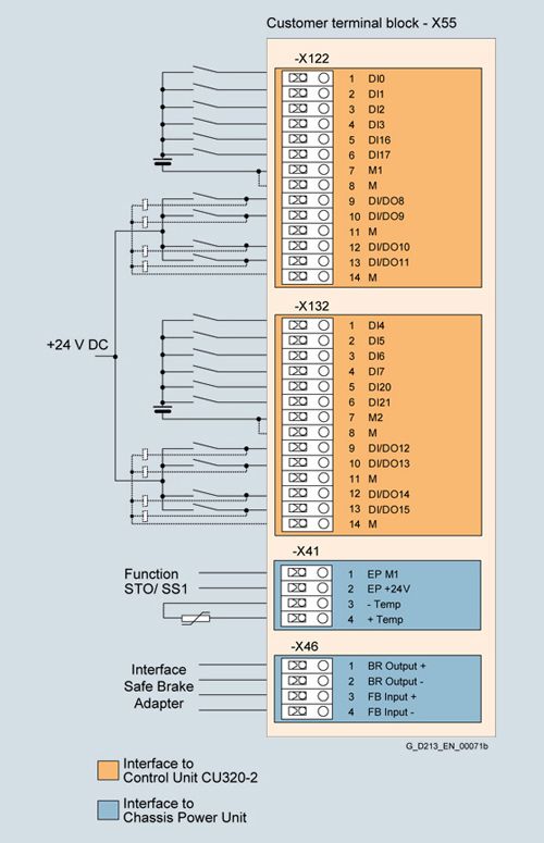
Terminal assignment of customer terminal block -X55
Terminal block -X55-X122 digital inputs/outputs
Terminal
Designation 1)
Technical data
1
DI 0
Voltage -30 V to +30 V DC
Current consumption, typical: 9 mA at 24 V DCElectrical isolation: The reference potential is terminal M1
Level (incl. ripple)
High level: 15 V ... 30 V
Low level: -30 V ... +5 VInput delay (typ.):
at 0 → 1: 50 μs
at 1 → 0: 150 μs2
DI 1
3
DI 2
4
DI 3
5
DI 16
6
DI 17
7
M1
Reference potential for terminals 1 to 6
8
M
Ground
9
DI/DO 8
As input:
Voltage -30 V ... +30 V DC
Current consumption, typical: 9 mA at 24 V DCLevel (incl. ripple)
High level: 15 V ... 30 V
Low level: -30 V ... +5 VFast inputs: 2)
DI/DO 8, 9, 10 and 11Input delay (typ.):
at 0 → 1: 5 μs
at 1 → 0: 50 μsAs output:
Voltage DC 24 V
max. Load current per output: 500 mA
continuously short-circuit proofOutput delay (typ./max.): 3)
at 0 → 1: 150 μs/400 μs
at 1 → 0: 75 μs/100 μsSwitching frequency:
For resistive load: max. 100 Hz
For inductive load: max. 0.5 Hz
For lamp load: max. 10 Hz
Max. Lamp load: 5 W10
DI/DO 9
11
M
12
DI/DO 10
13
DI/DO 11
14
M
Max. connectable cross-section: 1.5 mm2
1) DI: Digital input
DI/DO: Bidirectional digital input/output
M: Electronics ground
M1: Reference ground.2) Can be used as measuring probe input or input for the external zero mark.
3) Data for: Ucc = 24 V; load 48 Ω; High (1) = 90 % Uout; Low (0) = 10 % Uout.
Terminal block -X55-X132 digital inputs/outputs
Terminal
Designation 1)
Technical data
1
DI 4
Voltage -30 V to +30 V DC
Current consumption, typical: 9 mA at 24 V DCElectrical isolation: The reference potential is terminal M2
Level (incl. ripple)
High level: 15 V ... 30 V
Low level: -30 V ... +5 VInput delay (typ.):
at 0 → 1: 50 μs
at 1 → 0: 150 μs2
DI 5
3
DI 6
4
DI 7
5
DI 20
6
DI 21
7
M2
Reference potential for terminals 1 to 6
8
M
Ground
9
DI/DO 12
As input:
Voltage -30 V ... +30 V DC
Current consumption, typical: 9 mA at 24 V DCLevel (incl. ripple)
High level: 15 V ... 30 V
Low level: -30 V ... +5 VFast inputs: 2)
DI/DO 12, 13, 14 and 15Input delay (typ.):
at 0 → 1: 5 μs
at 1 → 0: 50 μsAs output:
Voltage DC 24 V
max. Load current per output: 500 mA
continuously short-circuit proofOutput delay (typ./max.): 3)
at 0 → 1: 150 μs/400 μs
at 1 → 0: 75 μs/100 μsSwitching frequency:
For resistive load: max. 100 Hz
For inductive load: max. 0.5 Hz
For lamp load: max. 10 Hz
Max. Lamp load: 5 W10
DI/DO 13
11
M
12
DI/DO 14
13
DI/DO 15
14
M
Max. connectable cross-section: 1.5 mm2
1) DI: Digital input
DI/DO: Bidirectional digital input/output
M: Electronics ground
M2: Reference ground.2) Can be used as measuring probe input or input for the external zero mark.
3) Data for: Ucc = 24 V; load 48 Ω; High (1) = 90 % Uout; Low (0) = 10 % Uout.
Terminal block -X55-X41 temperature sensor connection
Terminal
Function
Technical data
1
EP M1
(enable pulses)Supply voltage 24 V DC (20.4 ... 28.8 V DC)
Current consumption: 10 mASignal propagation times:
L → H: 100 μs
H → L: 1000 μsThe pulse inhibit function is only available when Safety Integrated Basic Functions are enabled
2
EP +24 V
(enable pulses)3
-Temp
Temperature sensor connection for motor temperature sensing:
KTY84‑1C130, PTC, Pt1004
+Temp
Max. connectable cross-section: 2.5 mm2
Terminal block -X55-X46 brake control and monitoring
Terminal
Function
Technical data
1
BR output +
The interface is used to connect the Safe Brake Adapter
2
BR output -
3
FB input +
4
FB input -
Max. connectable cross-section: 1.5 mm2