
- Каталог оборудования Siemens
- Каталог продуктов Siemens Industry
- Приводная техника
- Преобразователи
- Стандартные преобразователи
- Общая информация о базовых преобразователях SINAMICS V
- Преобразователи частоты общего назначения SINAMICS G
- Высокопроизводительные преобразователи SINAMICS S
- Сервопреобразователь SINAMICS S110
- SINAMICS S120
- SINAMICS S120M distributed servo drive
- SINAMICS S120 Combi
- SINAMICS S120 Chassis Format Units
- SINAMICS S120 Cabinet Modules
- SINAMICS S150 converter cabinet units
- MICROMASTER
- SIPLUS POSMO A
- SIMODRIVE POSMO
- LOHER DYNAVERT Drive System
- Преобразователи на среднее напряжение
- Преобразователи постоянного тока
- Стандартные преобразователи
- Двигатели переменного тока
- Generators
- Мотор-редукторы
- Flender Gear Units
- Couplings
- Инструментальное программное обеспечение
- Дополнительные компоненты
- Преобразователи
- Техника автоматизации
- Energy
- Автоматизация и безопасность зданий
- Низковольтная коммутационная техника
- Технология безопасности
- Системные решения и продукты для отраслей
- Сервис
- Приводная техника

Auxiliary Power Supply Modules
- Заказные данные (4)
- Информационные материалы
Информационные материалы
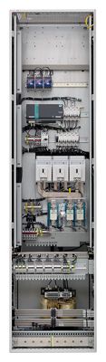
Auxiliary Power Supply Modules supply the auxiliary power supply for the SINAMICS S120 Cabinet Modules. Units connected to this auxiliary power supply system include the fans of the SINAMICS S120 devices installed in the Cabinet Modules. In addition, the auxiliary power supply system supplies the electronic modules with an external voltage of 24 V DC. This is required when the DC link is not charged, for instance, in order to maintain PROFIBUS/PROFINET communication.
Дизайн
The Auxiliary Power Supply Module is connected in the customer's plant to a voltage corresponding to the respective rated unit voltage.
The standard version contains the following components:
- Fuse switch disconnector with fuse monitoring for external evaluation
- Supply of the auxiliary power supply system with 3 fused auxiliary voltages:
- 24 V DC for the electronics power supply
- 230 V 2 AC to supply 230 V loads
- 380 V to 690 V 2 AC to supply the equipment fans
- Transformer with 230 V output voltage
- SITOP 24 V DC power supply
- 6-pole auxiliary power supply system (ready-wired), including connections for looping through to the next Cabinet Module
- Nickel-plated PE busbar (60 mm × 10 mm), including jumper for looping through to the next Cabinet Module
Интеграция
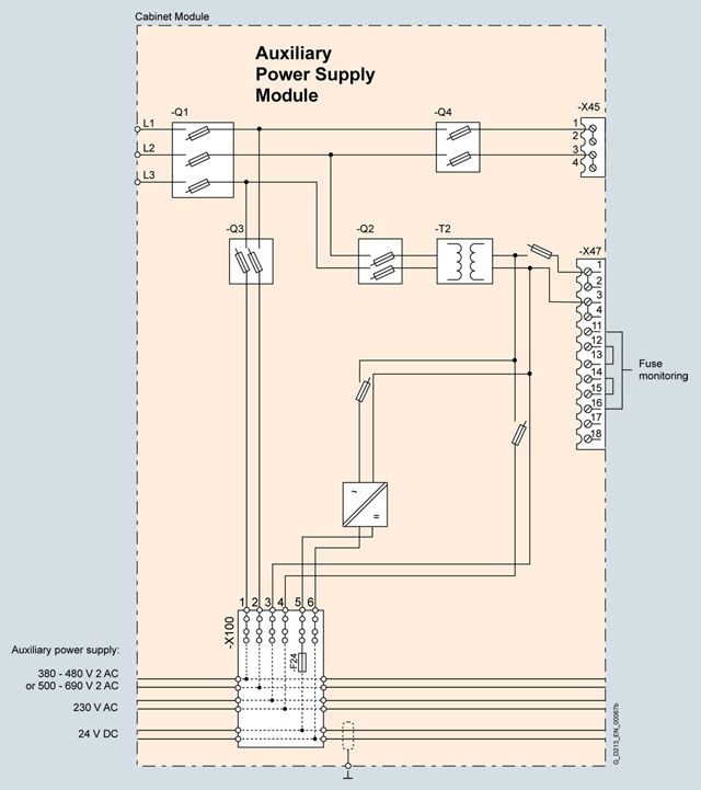
Block diagram: Auxiliary Power Supply Module
Технические данные
Auxiliary Power Supply Modules
6SL3700-0MX14-0AA3
6SL3700-0MX16-3AA3
6SL3700-0MX21-0AA3
6SL3700-0MX21-4AA3
System-side power supply
380 ... 690 V 3 AC
A
125
160
200
250
Line supply connection
- Conductor cross-section, max. (IEC)
mm2
150
150
150
150
Max. current carrying capacity
- Load connection
380 V ... 690 V AC
- To auxiliary power supply
A
63
80
100
100
- To customer terminal -X45
A
50
63
80
80
- Load connection
230 V 2 AC
- To auxiliary power supply
A
6
10
10
20
- To customer terminal -X45
A
8
10
10
20
- Load connection
24 V DC
- To auxiliary power supply
A
20
40
80
80
Cable cross-section, max.
- Connection -X45
mm2
16
16
16
16
- Connection -X47
mm2
2.5
2.5
2.5
2.5
Cooling air requirement
m3/s
Natural convection
Natural convection
Natural convection
Natural convection
PE/GND connection
PE bar
PE bar
PE bar
PE bar
- Busbar cross-section
mm2
600
600
600
600
- Conductor cross section, max. (IEC)
mm2
240
240
240
240
Degree of protection
IP20
IP20
IP20
IP20
Dimensions
- Width
mm
600
600
600
600
- Height 1)
mm
2200
2200
2200
2200
- Depth
mm
600
600
600
600
Weight, approx.
kg
170
180
210
240
Minimum short-circuit current 2)
A
3200
4000
5000
7000
1) The cabinet height increases by 250 mm with degree of protection IP21, and by 400 mm with degrees of protection IP23, IP43 and IP54.
2) Current required to ensure reliable tripping of installed protective devices.