
- Каталог оборудования Siemens
- Каталог продуктов Siemens Industry
- Приводная техника
- Преобразователи
- Стандартные преобразователи
- Общая информация о базовых преобразователях SINAMICS V
- Преобразователи частоты общего назначения SINAMICS G
- Высокопроизводительные преобразователи SINAMICS S
- Сервопреобразователь SINAMICS S110
- SINAMICS S120
- SINAMICS S120M distributed servo drive
- SINAMICS S120 Combi
- SINAMICS S120 Chassis Format Units
- SINAMICS S120 Cabinet Modules
- Air-cooled units
- Line Connection Modules
- Basic Line Modules
- Smart Line Modules
- Active Line Modules including Active Interface Modules
- Active Line Modules including Active Interface Modules
- Motor Modules Booksize format
- Motor Modules Chassis format
- Central Braking Modules
- Auxiliary Power Supply Modules
- Customer terminal block -X55
- Liquid-cooled units
- Options
- Supplementary system components
- Order-specific integration engineering
- Customized solutions
- Air-cooled units
- SINAMICS S150 converter cabinet units
- MICROMASTER
- SIPLUS POSMO A
- SIMODRIVE POSMO
- LOHER DYNAVERT Drive System
- Преобразователи на среднее напряжение
- Преобразователи постоянного тока
- Стандартные преобразователи
- Двигатели переменного тока
- Generators
- Мотор-редукторы
- Flender Gear Units
- Couplings
- Инструментальное программное обеспечение
- Дополнительные компоненты
- Преобразователи
- Техника автоматизации
- Energy
- Автоматизация и безопасность зданий
- Низковольтная коммутационная техника
- Технология безопасности
- Системные решения и продукты для отраслей
- Сервис
- Приводная техника

Active Line Modules including Active Interface Modules
- Заказные данные (17)
- Информационные материалы
Информационные материалы

Active Line Modules are regulated rectifier/regenerative units. They can supply energy to the DC link and return regenerative energy to the supply system.
In contrast to Basic Line Modules and Smart Line Modules, Active Line Modules generate a stabilized DC voltage that is kept constant despite fluctuations in the line voltage (the line voltage must remain within the permissible tolerance range). Active Line Modules draw a virtually sinusoidal current from the supply system and therefore do not cause any harmful current harmonics.
Braking Modules and braking resistors are required only if the drives need to be decelerated in a controlled manner after a power failure (i.e. when energy cannot be recovered to the supply).
Active Line Modules are suitable for connection to grounded TN/TT and non-grounded IT systems. The following voltages and power ratings are available:
Line voltage
Rated power
380 ... 480 V 3 AC
132 ... 900 kW
500 ... 690 V 3 AC
560 ... 1400 kW
Дизайн
Active Line Modules are always operated together with an Active Interface Module that contains the associated Clean Power Filter and pre-charging circuit. The integrated line filter ensures compliance with the EMC requirements for the "second environment".
The Active Line Module and Active Interface Module are supplied as a complete, fully wired unit, i.e. the customer does not need to supply any further cables or carry out any other wiring tasks.
Parallel connection of Active Line Modules to increase power rating
Active Line Modules are available for creating drive line-ups with more power. These modules can be operated in parallel on a common Line Connection Module and are arranged to the right and left of the Line Connection Module.
The power connections on the Active Line Module on the left of the Line Connection Module are a mirror image (article no. with "C" in the next to last position, example: 6SL3730‑7T.41.‑.BC3), which results in a very compact design for the line infeed.
Please note that only Active Line Modules with exactly the same power rating may be connected in parallel. The potential for imbalances in current distribution means that a current derating of 5% applies; this must be taken into account when the modules are dimensioned.
A connection of the Active Line Modules connected in parallel using DRIVE‑CLiQ must be taken into consideration during the engineering phase.
For additional information, please refer to the SINAMICS Low Voltage Engineering Manual.

Интеграция
The Active Line Module is controlled by the CU320‑2 Control Unit. Communication between the Control Unit and module is established via DRIVE‑CLiQ connections. The Active Interface Module is included in the scope of delivery for the Active Line Module.

Example of connection of an Active Line Module (frame size FI/FX and GI/GX)
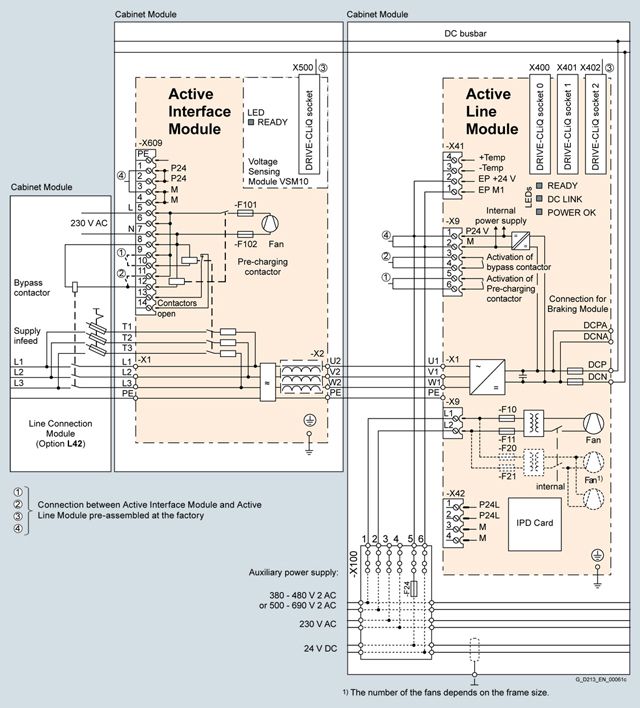
Example of connection of an Active Line Module (frame size HI/HX and JI/JX)
Технические данные
Line voltage 380 ... 480 V 3 AC
Active Line Modules
6SL3730-7TE32-1BA3
6SL3730-7TE32-6BA3
6SL3730-7TE33-8BA3
6SL3730-7TE35-0BA3
6SL3730-7TE36-1BA3
6SL3730-7TE38-4BA3
6SL3730-7TE41-0BA3
6SL3730-7TE41-4BA3
For a parallel circuit configuration,
mounted to the left of the Line Connection Module6SL3730-7TE41-0BC3
6SL3730-7TE41-4BC3
Rated power
- At Irated DC (50 Hz 400 V)
kW
132
160
235
300
380
500
630
900
- At IH DC (50 Hz 400 V)
kW
115
145
210
270
335
465
545
780
- At Irated DC (60 Hz 460 V)
hp
200
250
400
500
600
700
900
1250
- At IH DC (60 Hz 460 V)
hp
150
200
300
400
500
700
800
1000
DC link current
- Rated current Irated DC
A
235
291
425
549
678
940
1103
1574
- Base-load current IH DC1)
A
209
259
378
489
603
837
982
1404
- Maximum current Imax DC
A
352
436
637
823
1017
1410
1654
2361
Infeed/regenerative feedback current
- Rated current Irated I
A
210
260
380
490
605
840
985
1405
- Maximum current Imax I
A
315
390
570
735
907
1260
1477
2107
Current demand
- 24 V DC auxiliary power supply
A
1.27
1.27
1.52
1.52
1.57
1.57
1.67
1.67
- 230 V AC auxiliary power supply
A
0.6
0.6
1.2
1.2
4.6
4.6
4.9
4.9
- 400 V AC 2)
A
0.63
1.13
1.8
1.8
3.6
3.6
5.4
5.4
DC link capacitance
- Active Line Module
μF
4200
5200
7800
9600
12600
16800
18900
28800
- Drive line-up, max.
μF
41600
41600
76800
76800
134400
134400
230400
230400
Power loss, max. 3)
- At 50 Hz 400 V
kW
4.3
4.9
6.9
8.7
11.7
13.8
17.6
21.8
- At 60 Hz 460 V
kW
4.4
5.1
7.2
9.0
12.1
14.3
18.3
22.7
Cooling air requirement
m3/s
0.47
0.47
0.83
0.83
1.18
1.18
1.48
1.48
Sound pressure level LpA 4)
(1 m) at 50/60 Hz
dB
71/73
71/73
72/74
72/74
77/79
77/79
78/80
78/80
PE/GND connection
PE bar
PE bar
PE bar
PE bar
PE bar
PE bar
PE bar
PE bar
- Busbar cross-section
mm2
600
600
600
600
600
600
600
600
- Conductor cross section, max. (IEC)
mm2
240
240
240
240
240
240
240
240
Cable length, max. 5)
- Shielded
m
2700
2700
2700
2700
3900
3900
3900
3900
- Unshielded
m
4050
4050
4050
4050
5850
5850
5850
5850
Degree of protection
IP20
IP20
IP20
IP20
IP20
IP20
IP20
IP20
Dimensions
- Width
mm
800
800
800
800
1000
1000
1400
1400
- Height 6)
mm
2200
2200
2200
2200
2200
2200
2200
2200
- Depth
mm
600
600
600
600
600
600
600
600
Weight, approx.
kg
380
380
530
530
930
930
1360
1360
Frame size
FX + FI
FX + FI
GX + GI
GX + GI
HX + HI
HX + HI
JX + JI
JX + JI
Short-circuit current rating according to IEC
kA
65
65
65
65
65
84
84
100
Minimum short-circuit current 7)
A
6200
10500
10500
10500
12000
2000
4000
6400
1) The base-load current IH DC is the basis for a duty cycle of 150 % for 60 s or Imax DC for 5 s with a duty cycle duration of 300 s.
2) The current demand for the 400 V AC auxiliary power supply is drawn from the line input voltage.
3) The specified power loss represents the maximum value at 100% utilization. The value is lower under normal operating conditions.
4) Total sound pressure level of Active Interface Module and Active Line Module.
5) Total of all motor cables and DC link. Longer cable lengths for specific configurations are available on request.
6) The cabinet height increases by 250 mm with degree of protection IP21, and by 400 mm with degrees of protection IP23, IP43 or IP54.
7) Current required to ensure reliable tripping of installed protective devices.
Line voltage 500 ... 690 V 3 AC
Active Line Modules
6SL3730-7TG35-8BA3
6SL3730-7TG37-4BA3
6SL3730-7TG41-0BA3
6SL3730-7TG41-3BA3
For a parallel circuit configuration,
mounted to the left of the Line Connection Module6SL3730-7TG37-4BC3
6SL3730-7TG41-0BC3
6SL3730-7TG41-3BC3
Rated power
- At Irated DC (50 Hz 690 V)
kW
630
800
1100
1400
- At IH DC (50 Hz 690 V)
kW
620
705
980
1215
- At Irated DC (50 Hz 500 V)
kW
447
560
780
965
- At IH DC (50 Hz 500 V)
kW
450
510
710
880
- At Irated DC (60 Hz 575 V)
hp
675
900
1250
1500
- At IH DC (60 Hz 575 V)
hp
506
600
1000
1250
DC link current
- Rated current Irated DC
A
644
823
1148
1422
- Base-load current IH DC1)
A
573
732
1022
1266
- Maximum current Imax DC
A
966
1234
1722
2133
Infeed/regenerative feedback current
- Rated current Irated I
A
575
735
1025
1270
- Maximum current Imax I
A
862
1102
1537
1905
Current demand 2)
- 24 V DC auxiliary power supply
A
1.57
1.67
1.87
1.87
- 230 V AC auxiliary power supply
A
4.6
4.9
4.9
4.9
- 500 V AC
A
3.0
4.4
4.4
4.4
- 690 V AC
A
2.1
3.1
3.1
3.1
DC link capacitance
- Active Line Module
μF
7400
11100
14400
19200
- Drive line-up, max.
μF
59200
153600
153600
153600
Power loss, max. 3)
- At 50 Hz 500/690 V
kW
13.6
19.2
22.8
26.1
- At 60 Hz 575 V
kW
13.0
18.6
22.1
24.9
Cooling air requirement
m3/s
1.18
1.48
1.48
1.48
Sound pressure level LpA 4)
(1 m) at 50/60 Hz
dB
77/79
77/79
77/79
77/79
PE/GND connection
PE bar
PE bar
PE bar
PE bar
- Busbar cross-section
mm2
600
600
600
600
- Conductor cross section, max. (IEC)
mm2
240
240
240
240
Cable length, max. 5)
- Shielded
m
2250
2250
2250
2250
- Unshielded
m
3375
3375
3375
3375
Degree of protection
IP20
IP20
IP20
IP20
Dimensions
- Width
mm
1000
1400
1400
1400
- Height 6)
mm
2200
2200
2200
2200
- Depth
mm
600
600
600
600
Weight, approx.
kg
930
1360
1360
1360
Frame size
HX + HI
JX + JI
JX + JI
JX + JI
Short-circuit current rating according to IEC
kA
65
84
100
100
Minimum short-circuit current 7)
A
9000
10500
2500
3200
- For connection in parallel
A
–
4000
4000
5000
1) The base-load current IH DC is the basis for a duty cycle of 150 % for 60 s or Imax DC for 5 s with a duty cycle duration of 300 s.
2) The current demand for the 500 V/690 V AC auxiliary power supply is drawn from the line input voltage.
3) The specified power loss represents the maximum value at 100% utilization. The value is lower under normal operating conditions.
4) Total sound pressure level of Active Interface Module and Active Line Module.
5) Total of all motor cables and DC link. Longer cable lengths for specific configurations are available on request.
6) The cabinet height increases by 250 mm with degree of protection IP21, and by 400 mm with degrees of protection IP23, IP43 or IP54.
7) Current required to ensure reliable tripping of installed protective devices.