
- Каталог оборудования Siemens
- Каталог продуктов Siemens Industry
- Приводная техника
- Преобразователи
- Стандартные преобразователи
- Общая информация о базовых преобразователях SINAMICS V
- Преобразователи частоты общего назначения SINAMICS G
- Высокопроизводительные преобразователи SINAMICS S
- Сервопреобразователь SINAMICS S110
- SINAMICS S120
- SINAMICS S120M distributed servo drive
- SINAMICS S120 Combi
- SINAMICS S120 Chassis Format Units
- SINAMICS S120 Cabinet Modules
- SINAMICS S150 converter cabinet units
- MICROMASTER
- SIPLUS POSMO A
- SIMODRIVE POSMO
- LOHER DYNAVERT Drive System
- Преобразователи на среднее напряжение
- Преобразователи постоянного тока
- Стандартные преобразователи
- Двигатели переменного тока
- Generators
- Мотор-редукторы
- Flender Gear Units
- Couplings
- Инструментальное программное обеспечение
- Дополнительные компоненты
- Преобразователи
- Техника автоматизации
- Energy
- Автоматизация и безопасность зданий
- Низковольтная коммутационная техника
- Технология безопасности
- Системные решения и продукты для отраслей
- Сервис
- Приводная техника

Central Braking Modules
- Заказные данные (12)
- Информационные материалы
Информационные материалы

Central Braking Modules limit the DC link voltage at a central location in the drive line-up when the motors are operating in generator mode and energy recovery to the supply system is not possible. If, in regenerative mode, the voltage of the DC busbar exceeds a limit value, an externally installed braking resistor is switched in, thus restricting the voltage from increasing further. The regenerative energy is converted into heat. The braking resistor is switched in by the Braking Unit integrated in the Cabinet Module, which is equipped with state-of-the-art MOSFET/IGBT semiconductors.
Central Braking Modules are an alternative to the optional Braking Modules (options L61/L62 or L64/L65) and are particularly suitable when high braking powers are required in a drive line-up. The required braking power can also be increased by connecting units in parallel.
Line voltage
DC link voltage
Braking power P150
380 ... 480 V 3 AC
510 ... 720 V DC
500 kW/1000 kW
500 ... 600 V 3 AC
675 ... 900 V DC
550 kW/1100 kW
660 … 690 V 3 AC
890 ... 1035 V DC
630 kW/1200 kW
The built-in fan means that Central Braking Modules are also suitable for high continuous power levels.
Дизайн
The Central Braking Module is a cabinet unit with integrated braking chopper. Using state-of-the-art MOSFET/IGBT semiconductors, the power unit controls when the braking resistor is switched-in.
Central Braking Modules are designed as a 400 mm wide cabinet module. Its connection to the DC link is protected by fuses.
Central Braking Modules require braking resistors that must be externally mounted and which can be ordered separately. The cables to the resistors can be connected to lugs which are specially prepared for plant application and which are located in the connection area of the cabinet.
The power units have diagnostics LEDs for the display of faults and also a control output for the communication of faults. The Central Braking Module can be disabled externally via a control input.
The arrangement in the DC link system is subject to specific configuring rules.
For additional information, please refer to the SINAMICS Low Voltage Engineering Manual.Характеристика
Central Braking Modules are dimensioned for braking powers with the following duty cycles:
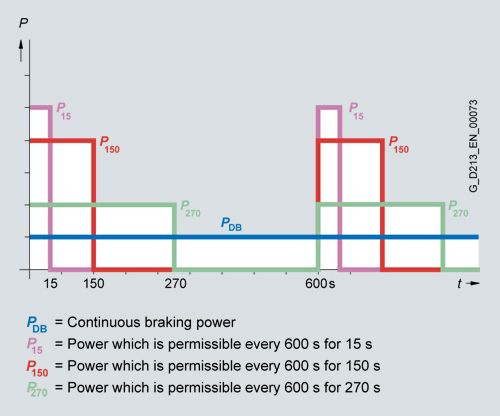
Braking powers of the Central Braking Modules
The braking powers are subject to a cycle time of 600 s. P150 is assumed to be the rated braking power. The braking resistors can be assigned according to these power ratings.
In most applications, Central Braking Modules are only used for occasional braking operations, e.g. stopping a drive in an emergency. Low-cost braking resistors in degree of protection IP21 are specifically offered for these types of applications; these braking resistors are dimensioned for braking powers PBR with the following duty cycle:
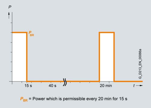
Duty cycle for braking resistors
Braking resistors with a higher braking power and shorter cycle times are available on request.
Интеграция

Example of connection of a Central Braking Module
Технические данные
Central Braking Modules
6SL3700-1AE35-0AA3
6SL3700-1AE41-0AA3
6SL3700-1AF35-5AA3
6SL3700-1AF41-1AA3
6SL3700-1AH36-3AA3
6SL3700-1AH41-2AA3
Line voltage
380 ... 480 V
500 ... 600 V
660 ... 690 V
Braking power P150
kW
500
1000
550
1100
630
1200
Continuous braking power PDB
kW
200
370
220
420
240
460
Braking current for P150
A
650
1200
580
1100
520
1000
Current demand 1)
- 230 V 2 AC
A
0.4
0.4
0.4
0.4
0.4
0.4
Power loss, max. 2)
At 50 Hz 400/500/690 V
kW
0.8
1.5
0.8
1.5
0.8
1.5
DC link capacitance
μF
8160
9720
7640
8680
7640
8680
Cooling air requirement
m3/s
0.14
0.14
0.14
0.14
0.14
0.14
Sound pressure level LpA
(1 m) at 50/60 Hz
dB
55
55
55
55
55
55
Braking resistor connection
M12 screws
M12 screws
M12 screws
M12 screws
M12 screws
M12 screws
- Conductor cross section, max. (IEC)
mm2
2 × 240
2 × 240
2 × 240
2 × 240
2 × 240
2 × 240
PE/GND connection
PE bar
PE bar
PE bar
PE bar
PE bar
PE bar
- Busbar cross-section
mm2
600
600
600
600
600
600
- Conductor cross section, max. (IEC)
mm2
240
240
240
240
240
240
Degree of protection
IP20
IP20
IP20
IP20
IP20
IP20
Dimensions
- Width
mm
400
400
400
400
400
400
- Height 3)
mm
2200
2200
2200
2200
2200
2200
- Depth
mm
600
600
600
600
600
600
Weight, approx.
kg
230
230
230
230
230
230
Frame size
mm
400
400
400
400
400
400
1) Current demand of the fans.
2) The specified power loss represents the maximum value at 100% utilization. The value is lower under normal operating conditions.
3) The cabinet height increases by 250 mm with degree of protection IP21, and by 400 mm with degrees of protection IP23, IP43 and IP54.
Braking resistors
6SL3000-1BE35-0AA0
6SL3000-1BE41-0AA0
6SL3000-1BF35-5AA0
6SL3000-1BF41-1AA0
6SL3000-1BH36-3AA0
6SL3000-1BH41-2AA0
Line voltage
380 ... 480 V
500 ... 600 V
660 ... 690 V
Braking power PBR
kW
500
1000
550
1100
630
1200
Continuous braking power PDB
kW
23
58
34
62
42
75
Resistance value
Ω
0.95
0.49
1.35
0.69
1.8
0.95
Degree of protection
IP21
IP21
IP21
IP21
IP21
IP21
Dimensions
- Width
mm
960
960
960
960
960
960
- Height
mm
620
620
620
620
620
620
- Depth
mm
790
1430
1110
1430
1110
1430
Weight, approx.
kg
82
170
110
180
124
196