
- Каталог оборудования Siemens
- Каталог продуктов Siemens Industry
- Приводная техника
- Преобразователи
- Двигатели переменного тока
- Generators
- Мотор-редукторы
- Flender Gear Units
- Couplings
- Technical information
- Selection of the coupling series
- Flexible couplings N-EUPEX and N-EUPEX DS series
- Flexible couplings BIPEX series
- Flexible couplings N-BIPEX series
- Flexible couplings RUPEX series
- Highly flexible couplings ELPEX series
- Highly flexible couplings ELPEX-B series
- Torsionally rigid gear couplings ZAPEX ZW series
- Torsionally Rigid Gear Couplings - ZAPEX ZN Series
- Torsionally rigid all-steel couplings ARPEX series
- SIPEX and BIPEX-S Backlash-free Couplings
- Non-positively acting couplings FLUDEX
- Taper clamping bushes
- Инструментальное программное обеспечение
- Дополнительные компоненты
- Техника автоматизации
- Energy
- Автоматизация и безопасность зданий
- Низковольтная коммутационная техника
- Технология безопасности
- Системные решения и продукты для отраслей
- Сервис
- Приводная техника
ARPEX ARS-6 series
- Информационные материалы
Информационные материалы


Coupling can be designed for potentially explosive environments.
Область применения
ARPEX couplings of the ARS-6 series are a versatile coupling solution which thanks to standard modular components can be used for most drive requirements at a low to medium speed. Torques of between 170 and 106000 Nm can be transmitted at a permitted angular misalignment of 0.7°. The open flange form is regarded as very easy to fit and has easily accessible screw connection points. On most types, the intermediate spacer can be radially fitted without moving the connected units.
Main areas of application for the ARS-6 series:
- Paper-making machines
- Printing machines
- Compressors
- Pumps
- Fans and blowers
- Film and foil machines
- Generators
- Presses
- Metalworking machines
- Conveyors
- Crane systems
- Textile machines
- Plastics processing machines
- Centrifuges
Дизайн
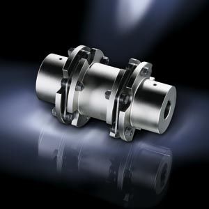
The classic design of an ARPEX couplings of the ARS-6 series is shown in the following illustration. The plate packs are bolted alternately between the flanges of the coupling hubs and the intermediate spacer. Up to size 280-6 close-fitting bolts and from size 305-6 conical screw connections are used for fastening. A large number of intermediate spacer and shafts, hubs and flanges can be combined and thus cover a large number of possible drive requirements.

Design of an ARPEX coupling, ARS-6 series, type NEN
Variants of the ARPEX coupling, ARS-6 series
Types
NEN, BEN, BEB
Variant with standard intermediate spacer, many sizes available from stock
NON, BON
Variant with shortest intermediate spacer
NUN, BUN, BUB
Variant with split intermediate spacer
NHN
Variant with intermediate spacer for customer-specific shaft distance
NZN
Variant with reinforced intermediate spacer
NWN
Variant with intermediate shaft
All coupling types can be very easily combined with further standard components in the ARPEX modular system. Jumbo hubs are used to permit larger maximum bores.
Clamping hubs transmit torque by friction without the use of parallel keys. F, D and C flanges offer many different possibilities for flange connection.The coupling parts of the ARPEX ARS-6 series are machined on all sides. Exceptions are H and Z spacers and intermediate shafts. The spacers are delivered with unmachined, primed spacer tube.
Higher torques and maximum speeds with similar coupling outer diameters DA can be achieved with the ARPEX ARC-8/-10 series.
Further application-specific coupling types are available in selection module x.CAT at www.flender.com. Dimension sheets and further information are available on request.
Особенности
ARPEX couplings of the ARS-6 series are outstanding for their versatility. Most standard components are available from stock, resulting in short delivery times. Their use in potentially explosive environments in accordance with Directive 94/9/EC is possible.
Технические данные
Power ratings
Size
Rated torque
Maximum torque
Overload torque
Fatigue torque
Maximum speed
Maximum permitted shaft misalignment
Torsional stiffness
DA
TKN
TKmax
TKOL
TKW
nKmax
±ΔKa
±ΔKw
±ΔKr
CTdyn
NHN
NZN
NWNNEN/BEN
BEB/NUN
BUN/BUBNON
BONNEN
BEN/BEBNUN
BUN/BUBNON
BONNHN
NZN
NWN
Nm
Nm
Nm
Nm
rpm
mm
mm
mm
mm
MNm/rad
MNm/rad
MNm/rad
MNm/rad
MNm/rad
MNm/rad
78-6
170
320
510
85
13400
1.10
0.7°
12.1
0.57
0.53
0.05
0.04
0.05
0.012
0.032
0.05
105-6
270
510
810
135
10000
1.80
12.1
0.88
0.53
0.09
0.09
0.09
0.024
0.070
0.09
125-6
490
930
1470
245
8400
2.02
12.1
1.04
0.68
0.17
0.17
0.18
0.043
0.141
0.19
140-6
700
1330
2100
350
7500
2.40
12.1
1.28
0.72
0.22
0.22
0.24
0.066
0.203
0.25
165-6
1250
2370
3750
625
6350
2.74
12.0
1.49
0.84
0.33
0.34
0.36
0.114
0.317
0.39
175-6
2000
3800
6000
1000
6000
2.86
12.0
1.55
0.98
0.48
0.50
0.52
0.196
0.443
0.57
195-6
3000
5700
9000
1500
5350
3.06
12.0
1.55
0.98
0.67
0.69
0.73
0.302
0.614
0.79
210-6
4400
8300
13200
2200
5000
3.14
12.0
1.77
1.10
0.77
0.78
0.82
0.352
0.669
0.88
240-6
5700
10800
17100
2850
4350
3.70
12.0
1.93
1.20
1.24
1.26
1.32
0.568
1.04
1.40
255-6
7600
14400
22800
3800
4100
3.84
11.9
2.09
1.50
1.39
1.42
1.46
0.697
1.22
1.57
280-6
10000
19000
30000
4600
3750
4.18
11.9
2.53
1.53
1.55
1.57
1.65
0.881
1.42
1.73
305-6
12000
21000
36000
5000
3400
4.46
11.9
2.72
1.80
2.83
2.87
3.05
1.51
2.71
3.32
335-6
18000
32000
54000
7500
3100
4.84
11.9
2.88
1.89
3.85
3.92
4.14
2.11
3.62
4.49
372-6
24000
43000
72000
10000
2800
4.98
11.8
3.03
2.16
5.72
5.84
6.12
3.14
–
6.75
407-6
34000
61000
102000
14000
2550
5.50
11.8
3.31
2.26
7.25
7.42
7.79
5.06
–
8.51
442-6
43000
77000
129000
18000
2350
6.02
11.8
3.59
2.48
10.0
10.2
10.8
7.42
–
11.9
487-6
55000
99000
165000
23000
2150
6.80
11.7
4.09
2.64
11.7
11.9
12.7
9.25
–
13.6
522-6
69000
124000
207000
29000
2000
7.34
11.7
4.35
2.86
14.0
14.3
15.1
11.4
–
16.2
572-6
92000
166000
276000
38000
1800
7.86
11.6
4.87
3.02
17.9
18.3
19.4
15.2
–
20.7
602-6
106000
191000
318000
44000
1700
8.24
11.6
5.13
3.24
21.1
21.7
22.9
18.2
–
24.5
The permitted shaft misalignments ΔKa, ΔKr and ΔKw are maximum values and must not occur at the same time (see following table).
The permitted shaft misalignment ΔKr for types NHN, NZN and NWN applies to a coupling with shaft distance S = 1000 mm.
For other shaft distances the permitted radial misalignment can be determined with the following formula:
ΔKr = (S – S1) · tan (ΔKw).
The shaft distance S is shown on the table for the type.TKmax permitted only five times per hour.
The values for torsional stiffness apply to the complete coupling. In the case of types NHN and NZN to a coupling with shaft distance S = 1000 mm. In the case of type NWN, the torsional stiffness applies to a coupling without intermediate or torsion shaft. The torsional stiffness of the plate packs applies to the rated coupling torque TKN. To determine the torsional stiffness for a specific operating point, e.g. for calculating torsional vibration, the manufacturer must be consulted.
Permitted shaft misalignments
Size
Permitted angular misalignment ±ΔKw
0.0°
0.1°
0.2°
0.3°
0.4°
0.5°
0.6°
0.7°
DA
Permitted axial misalignment ±ΔKa in mm
78-6
1.10
0.94
0.79
0.63
0.47
0.31
0.16
0.00
105-6
1.80
1.54
1.29
1.03
0.77
0.51
0.26
0.00
125-6
2.02
1.73
1.44
1.15
0.87
0.58
0.29
0.00
140-6
2.40
2.06
1.71
1.37
1.03
0.69
0.34
0.00
165-6
2.74
2.35
1.96
1.57
1.17
0.78
0.39
0.00
175-6
2.86
2.45
2.04
1.63
1.23
0.82
0.41
0.00
195-6
3.06
2.62
2.19
1.75
1.31
0.87
0.44
0.00
210-6
3.14
2.69
2.24
1.79
1.35
0.90
0.45
0.00
240-6
3.70
3.17
2.64
2.11
1.59
1.06
0.53
0.00
255-6
3.84
3.29
2.74
2.19
1.65
1.10
0.55
0.00
280-6
4.18
3.58
2.99
2.39
1.79
1.19
0.60
0.00
305-6
4.46
3.82
3.19
2.55
1.91
1.27
0.64
0.00
335-6
4.84
4.15
3.46
2.77
2.07
1.38
0.69
0.00
372-6
4.98
4.27
3.56
2.85
2.13
1.42
0.71
0.00
407-6
5.50
4.71
3.93
3.14
2.36
1.57
0.79
0.00
442-6
6.02
5.16
4.30
3.44
2.58
1.72
0.86
0.00
487-6
6.80
5.83
4.86
3.89
2.91
1.94
0.97
0.00
522-6
7.34
6.29
5.24
4.19
3.15
2.10
1.05
0.00
572-6
7.86
6.74
5.61
4.49
3.37
2.25
1.12
0.00
602-6
8.24
7.06
5.89
4.71
3.53
2.35
1.18
0.00