
- Каталог оборудования Siemens
- Каталог продуктов Siemens Industry
- Приводная техника
- Преобразователи
- Двигатели переменного тока
- Generators
- Мотор-редукторы
- Flender Gear Units
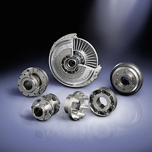
- Couplings
- Technical information
- Selection of the coupling series
- Flexible couplings N-EUPEX and N-EUPEX DS series
- Flexible couplings BIPEX series
- Flexible couplings N-BIPEX series
- Flexible couplings RUPEX series
- Highly flexible couplings ELPEX series
- Highly flexible couplings ELPEX-B series
- Torsionally rigid gear couplings ZAPEX ZW series
- Torsionally Rigid Gear Couplings - ZAPEX ZN Series
- Torsionally rigid all-steel couplings ARPEX series
- SIPEX and BIPEX-S Backlash-free Couplings
- Non-positively acting couplings FLUDEX
- Taper clamping bushes
- Инструментальное программное обеспечение
- Дополнительные компоненты
- Техника автоматизации
- Energy
- Автоматизация и безопасность зданий
- Низковольтная коммутационная техника
- Технология безопасности
- Системные решения и продукты для отраслей
- Сервис
- Приводная техника
Product code key
- Информационные материалы
Информационные материалы
The product code consists of a combination of digits and letters and is divided into three blocks linked by hyphens for better clarity. In blocks 1 and 2 the coupling series, the type and the size are encoded. Block 3 contains information applying only to the coupling specified in blocks 1 and 2. The three blocks of the product code are supplemented by information on the bore of the coupling hub parts and information on “Special types”.
The bore details with the code letter L always refer to the bore diameter D1 of the hub part shown on the left on the dimension drawing. The order code beginning with M always refers to the bore diameter D2 of the hub part shown on the right on the dimension drawing.
“Special types” are linked to the 3rd block of the product code by appending the code “-Z”. Special order requirements are, for example, fine balancing G6.3 or the ATEX design of the coupling.
With this product code key, the couplings shown in the catalog can be completely specified. No further textual details are required, they should be avoided. Couplings in special variants are specified with the digit 9 in the 4th place in the product code (block 1) and additionally with 00-0AA0 in positions 11 to 16. Series, type and size should, as far as possible, be specified in accordance with the coding for the standard coupling. By appending “-Z Y99”, plain text information can be included. The plain text information can then clearly specify the features of the special coupling.
Structure of the product code
Position
1
2
3
4
5
6
7
-
8
9
10
11
12
-
13
14
15
16
FLENDER Standard Couplings
Positions 1 to 3
digit, letter, letterType
2
L
C
Position 4
digitCoupling design
0 … 9
Places 5 to 6
digitsSeries
❑
❑
Positions 7 to 8
digitsSize
❑
❑
❑
Positions 9 and 10
lettersType, subassembly or component part
❑
❑
Position 11
digitShaft-hub connection, flange connection
❑
Position 12
digitShaft-hub connection, flange connection, V-belt pulley
❑
Positions 13 to 16
digit, letter, letter, digitVarious details
❑
❑
❑
❑
Bore specifications
Additional order codes for bores finished in delivery condition ∅ D1 and ∅ D2
Specification of a 9 in the 11th position of the product code (product code without „-Z“) with order codes L.. for ∅D1
and/or
specification of a 9 in the 12th position of the product code (product code without „-Z“) with order codes M.. for ∅D2Selection of order codes for diameter and tolerance in the following tables under "Bore specifications".
Special types
Additional order codes (product code with "-Z") and, if required, plain text
Selection of order codes in this catalog section and in catalog section 13 under "Special Types".
-Z