
- Каталог оборудования Siemens
- Каталог продуктов Siemens Industry
- Приводная техника
- Техника автоматизации
- Системы автоматизации
- Системы визуализации SIMATIC HMI
- Системы идентификации
- Промышленные коммуникации SIMATIC NET
- Промышленные аппараты управления SIRIUS
- Промышленные информационные технологии
- Управление на базе РС
- Системы управления процессом
- Контрольно-измерительные приборы
- Анализаторы процесса
- Блоки питания SITOP
- Продукты для специальных требований
- Energy
- Автоматизация и безопасность зданий
- Низковольтная коммутационная техника
- Технология безопасности
- Системные решения и продукты для отраслей
- Сервис
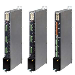
Power output modules
- Заказные данные (2)
- Аксессуары (1)
- Информационные материалы
Дизайн
- Modules enclosed in metal housing
- Connection of the phases via conductor rails
- Connection of the heat emitters by means of mating connectors (the heat emitter and mating connector must be ordered separately.)
- Channel fuses at the front
- Cooling is possible with the optional fan module for LA724I and LA724I HP power output modules, see "Fan module"
- Internal parallel bus interface
- 4 diagnostic LEDs for indicating channel/module faults
Функции
Power switching elements
LA724I and LA724I HP power output modules
- Power triacs with zero crossover switching
- Protection of triacs and opto-triacs against overvoltages by Transil diodes
LA724I SSR power output module
There are no power triacs here. The load is activated via external Solid State Relays (SSR).
Output power
LA724I power output module
- 24 power channels of 230 V each (8 outputs per phase)
- Max. 1 150 W switching capacity per output
- Max. 7 360 W switching capacity per phase
LA724I HP power output module
- 12 power output channels for 230 V/400 V (4 outputs per phase)
- Max. 2 300 W/4 000 W switching capacity per output
- Max. 9 200 W switching capacity per phase for star connection and max. 16 000 W switching capacity for delta connection
LA724I SSR power output module
24 channels with one digital control signal of 24 V (8 outputs per phase)
Forced ventilation
LA724I and LA724I HP power output modules
Depending on the switching capacity and ambient temperature, the power output modules may have to be forced ventilated. A fan module is available as an option for this purpose, see "Fan module".
For detailed information, refer to the "SIPLUS HCS724I Heater Control System" Operating Instructions, http://support.automation.siemens.com/WW/view/en/55336534.
Temperature monitoring
LA724I and LA724I HP power output modules
There is an NTC thermistor on the heat sink for monitoring its temperature. This temperature-dependent resistor outputs a signal to the SIMATIC S7‑300 at 92 °C ± 3 °C. A second switching threshold at 100 °C ± 3 °C switches off the power outputs of the module.
Supply voltage monitoring
LA724I SSR power output module
- The connected 24 V DC supply is monitored for failure. In the event of a failure, the outputs to the Solid State Relay (SSR) are deactivated.
- The drivers for the control outputs are monitored for correct functioning.
Fuses
LA724I power output module
- Each power output has a 5 A fuse in a fuse holder that is accessible from the front to protect the power triac, and one 32 A fuse per phase to limit the phase current.
LA724I HP power output module
- Each power output has a 10 A fuse in a fuse holder that is accessible from the front to protect the power triac, and one 40 A fuse per phase to limit the phase current.
LA716I SSR power output module
Protection for each channel is to be provided externally.
Diagnostics facilities
LA724I and LA724I HP power output modules
Diagnostics functions are provided as standard to detect the following faults:
- Internal fuse defective or triac at high-resistance
- Triac failed
- External fault such as blown fuse, heat emitter or cable breakage
If several heat emitters are connected to one output in parallel, failure of an individual heat emitter is detected by means of extended diagnostics.
LA724I SSR power output module
Two different diagnostics methods are possible:
- Diagnostics of voltages from the load circuit allows the following faults to be detected:
- Solid State Relay (SSR) cannot be closed, supply line to the SSR is interrupted, or external channel fuse has ruptured
- Solid State Relay (SSR) cannot be opened, break in emitter or wiring
- Diagnostics using the external current measuring module (see "Current measuring module") allow the following faults to be detected in addition (these diagnostics are recommended for fault detection in emitters connected in parallel):
- Rated voltage for channel has been exceeded
- Rated voltage for channel has been undershot
Технические данные
Order number
6BK1700-2BA00-0AA0
6BK1700-4BA70-0AA0
HCS Power output module LA724I
HCS Power Output Modul LA724I HP
General information
Product designation
Power module LA724I
Power module LA724I HP
Type of control of heat emitters
Half-wave control
Installation type/mounting
Mounting type
Screws in fixing lugs at top and bottom
Mounting position
vertical
Type of ventilation
Self ventilation or forced ventilation
Supply voltage
Rated value (AC)
230 V
400 V
Relative negative tolerance
18 %
Relative positive tolerance
15 %
Line frequency
● Rated value 1
50 Hz
● Rated value 2
60 Hz
● Relative symmetrical tolerance
5 %
Resistance thermometer (RTD)
● Design of electrical connection for supply voltage
Bus bar or ring cable lug
Power supply for the electronics
Design of the power supply
Power supply via central connection
Power electronics
Type of load
Ohmic load
Power capacity, max.
22 kW
48 kW
● for delta connection with fan at 40 °C, max.
36.5 kW
● for delta connection without fan at 40 °C, max.
22.6 kW
● for star connection with fan at 40 °C, max.
22 kW
21 kW
● for star connection without fan at 40 °C, max.
14.4 kW
13 kW
Switching capacity current per busbar, max.
120 A
Switching capacity current per phase, max.
32 A
40 A
Heating power
● Number of digital outputs
24
12
● Number of heat emitters per output, max.
5
● Output voltage for delta connection
400 V
● Output voltage for star connection
230 V
● Power carrying capacity per output, min.
75 W
● Power carrying capacity per output, max.
1 150 W
4 000 W
● Output current for heating power
5 A
10 A
● Design of short-circuit protection per output
Fuse 5 A
Fuse 16 A
● Design of overvoltage protection
Transil diodes
Integration and conversion time/resolution per channel
● Design of electrical connection at output for heating and fan
Socket strip, 8-pole
— Connectable conductor cross-sections, solid
1x (0.2 ... 1.5 mm²)
— Connectable conductor cross-sections, finely stranded with wire end processing
1x (0.2 ... 1.5 mm²)
— Connectable conductor cross-sections for AWG cables, stranded
28 ... 16
Interfaces
Interfaces/bus type
system interface
Interrupts/diagnostics/status information
Number of status displays
4
LED status display
1 LED green = LA status indicator, 3 LEDs red = fault indicator LA per phase
Diagnostics function
Voltage and current diagnosis
Diagnostic messages
● Wire-break
Yes
● Fuse blown
Yes
● Heat emitter defect
Yes
Integrated Functions
Monitoring functions
● Temperature monitoring
Yes
● Type of temperature monitoring
NTC thermistor
Measuring functions
● Current measurement
Yes
Measuring inputs for current
— Design of electrical connection at the measuring inputs for current
Internal
Potential separation
Design of electrical isolation
Optocoupler between main circuit and SELV / PELV
between the outputs
No
Isolation
Overvoltage category
III
EMC
EMC interference emission
Limit value class A to EN 55011 group 1
Electrostatic discharge acc. to IEC 61000-4-2
4 kV contact discharge / 8 kV air discharge
Field-related interference acc. to IEC 61000-4-3
10 V/m (80 ... 1 000 MHz), 3 V/m (1.4 ... 2.0 GHz), 1 V/m (2.0 ... 2.7 GHz)
Conducted interference due to burst acc. to IEC 61000-4-4
2 kV voltage supply cables / 2 kV signal cables
Conducted interference due to surge acc. to IEC 61000-4-5
on power supply and signal cables: 1 kV symmetrical, 2 kV unsymmetrical
Conducted interference due to high-frequency radiation acc. to IEC 61000-4-6
10 V (0.15 ... 80 MHz)
Degree and class of protection
IP degree of protection
IP20
Standards, approvals, certificates
Certificate of suitability
CE, KCC
Degree of pollution
2
Device tag according to DIN EN 81346-2
Q
Ambient conditions
Ambient temperature during operation
● min.
0 °C
● max.
55 °C
Ambient temperature during storage/transportation
● Storage, min.
-40 °C
● Storage, max.
70 °C
● Transportation, min.
-40 °C
● Transportation, max.
70 °C
Air pressure acc. to IEC 60068-2-13
● Operation, min.
860 hPa
● Operation, max.
1 080 hPa
● Storage, min.
660 hPa
● Storage, max.
1 080 hPa
● Installation altitude above sea level, max.
2 000 m
Relative humidity
● at 25 °C, max.
95 %
Vibrations
● Vibration resistance during operation acc. to IEC 60068-2-6
10 ... 58 Hz / 0.15 mm, 58 ... 150 Hz / 1 g
● Vibration resistance during storage acc. to IEC 60068-2-6
5 ... 9 Hz / 3.5 mm, 9 ... 500 Hz / 1 g
Shock testing
● Shock resistance acc. to IEC 60068-2-27
15 g / 11 ms / 3 shocks/axis
● Shock resistance acc. to IEC 60068-2-29
25 g / 6 ms / 1 000 shocks/axis
Dimensions
Width
50 mm
Height
480 mm
Depth
210 mm
Дополнительно
Design
for power output module
Type
Mating connectors
- for connection of heat emitter
(3 units required for each power output module)
LA724I, LA724I HP
40018384
- for the 24 V DC supply
LA724I SSR
A5E00210675
- for connection of Solid State Relay (SSR)
(3 units required for each power output module)
LA724I SSR
A5E00043661
- for connecting the current measuring module
LA724I SSR
A5E00210670
- for voltage diagnosticss
(3 units required for each power output module)
LA724I SSR
41818384
Data link
- 5 A quick blow/250 V
LA724I
200021116
- 16 A slow blow/500 V
(3 units required for each power output module)
LA724I HP
A5E01204540
Recommended Solid State Relay (SSR)
SIRIUS SC semiconductor relay/contactor,
e.g. 3RF2350‑1AA02:
semiconductor contactor 50 A,
40 °C,
control voltage 24 V,
screw connection