
- Каталог оборудования Siemens
- Каталог продуктов Siemens Industry
- Приводная техника
- Техника автоматизации
- Системы автоматизации
- Системы визуализации SIMATIC HMI
- Системы идентификации
- Промышленные коммуникации SIMATIC NET
- Промышленные аппараты управления SIRIUS
- Промышленные информационные технологии
- Управление на базе РС
- Системы управления процессом
- Контрольно-измерительные приборы
- Анализаторы процесса
- Блоки питания SITOP
- Продукты для специальных требований
- Energy
- Автоматизация и безопасность зданий
- Низковольтная коммутационная техника
- Технология безопасности
- Системные решения и продукты для отраслей
- Сервис
Central interface modules
- Заказные данные (1)
- Аксессуары (2)
- Информационные материалы
Информационные материалы
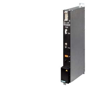
The central interface module is the intelligent processor module of the SIPLUS HCS724I heater control.
Дизайн
- Module encapsulated in metal enclosure
- Two LEDs for normal operation (green) and fault (red)
- PROFIBUS DP interface (up to 12 Mbaud)
- Rotary switch for setting the PROFIBUS DP address
- RS 232 C serial port
- Parallel bus interface to the power output modules
- Connection facility for up to 16 LA724I/LA724I HP/LA724I SSR power output modules per central interface module
- Expansion slot for line-voltage sensing submodule (option)
Функции
Communications
PROFIBUS DP
- Import of the parameter settings from the higher-level controller
- Transfer of the diagnostic information to the higher-level controller
Parallel bus (internal)
- Control and monitoring of max. 384 power output channels
Performance features
- Calculation of heat emitter control variables of power output channels
- Setpoints adjustable from 0% to 100% in steps of 0.5%
- Uniform load distribution over all power output channels and over all the SIPLUS HCS724I heating controllers operated in the group
- Simple adaptation to the respective production process by selecting one of up to four operating modes
- Mixed operation of the various power output modules is possible
Diagnostics
- Evaluation of diagnostics information from connected power output modules
- Phase-sequence detection indicating whether phases L1, L2, and L3 are correctly connected
- Automatic detection of the line frequency
Line synchronization
In order to ensure synchronization of the power output modules with the connected power supply, the system is synchronized with phase L1. The respective switch-on times for phases L2 and L3 are then calculated automatically.
Технические данные
Order number
6BK1700-2BA30-0AA0
HCS Central interface ZA724I
General information
Product designation
HCS central connection ZA724I
Installation type/mounting
Mounting type
Screws in fixing lugs at top and bottom
Mounting position
vertical
Type of ventilation
Self ventilation or forced ventilation
Supply voltage
Type of supply voltage
AC
Rated value (AC)
230 V
Relative negative tolerance
18 %
Relative positive tolerance
15 %
Line frequency
● Rated value 1
50 Hz
● Rated value 2
60 Hz
● Relative symmetrical tolerance
5 %
Mains buffering
● Mains/voltage failure stored energy time
20 ms
● Recovery time after power failure, typ.
1 s
Resistance thermometer (RTD)
● Design of electrical connection for supply voltage
Terminal, 2-pole
— Connectable conductor cross-sections, solid
1x (0.5 ... 2.5 mm²)
— Connectable conductor cross-sections, finely stranded with wire end processing
1x (0.5 ... 2.5 mm²)
— Connectable conductor cross-sections for AWG cables
26 ... 14
Power
Active power input
35 W
Hardware configuration
Type of power output connectable
LA724I / LA724I HP / LA724I SSR
Interfaces
Interfaces/bus type
PROFIBUS DP
PROFIBUS DP
● Transmission rate, max.
12 Mbit/s
● Design of electrical connection of PROFIBUS interface
9-pin sub D socket
Protocols
PROFIBUS DP
Yes
Interrupts/diagnostics/status information
Number of status displays
2
LED status display
LED green = status indicator, LED red = fault indicator
Isolation
Overvoltage category
III
EMC
EMC interference emission
Limit value class A to EN 55011 group 1
Electrostatic discharge acc. to IEC 61000-4-2
4 kV contact discharge / 8 kV air discharge
Field-related interference acc. to IEC 61000-4-3
10 V/m (80 ... 1 000 MHz), 3 V/m (1.4 ... 2.0 GHz), 1 V/m (2.0 ... 2.7 GHz)
Conducted interference due to burst acc. to IEC 61000-4-4
2 kV voltage supply cables / 2 kV signal cables
Conducted interference due to surge acc. to IEC 61000-4-5
On supply lines: 1 kV symmetrical, 2 kV asymmetrical, PROFIBUS cable asymmetrical 1 kV
Conducted interference due to high-frequency radiation acc. to IEC 61000-4-6
10 V (0.15 ... 80 MHz)
Degree and class of protection
IP degree of protection
IP20
Standards, approvals, certificates
Certificate of suitability
CE, KCC
Degree of pollution
2
Device tag according to DIN EN 81346-2
K
Ambient conditions
Ambient temperature during operation
● min.
0 °C
● max.
55 °C
Ambient temperature during storage/transportation
● Storage, min.
-40 °C
● Storage, max.
70 °C
● Transportation, min.
-40 °C
● Transportation, max.
70 °C
Air pressure acc. to IEC 60068-2-13
● Operation, min.
860 hPa
● Operation, max.
1 080 hPa
● Storage, min.
660 hPa
● Storage, max.
1 080 hPa
● Installation altitude above sea level, max.
2 000 m
Relative humidity
● at 25 °C, max.
95 %
Vibrations
● Vibration resistance during operation acc. to IEC 60068-2-6
10 ... 58 Hz / 0.15 mm, 58 ... 150 Hz / 1 g
● Vibration resistance during storage acc. to IEC 60068-2-6
5 ... 9 Hz / 3.5 mm, 9 ... 500 Hz / 1 g
Shock testing
● Shock resistance acc. to IEC 60068-2-27
15 g / 11 ms / 3 shocks/axis
● Shock resistance acc. to IEC 60068-2-29
25 g / 6 ms / 1 000 shocks/axis
Dimensions
Width
50 mm
Height
480 mm
Depth
210 mm