
- Каталог оборудования Siemens
- Каталог продуктов Siemens Industry
- Приводная техника
- Техника автоматизации
- Системы автоматизации
- Системы визуализации SIMATIC HMI
- Системы идентификации
- Промышленные коммуникации SIMATIC NET
- Промышленные аппараты управления SIRIUS
- Промышленные информационные технологии
- Управление на базе РС
- Системы управления процессом
- Контрольно-измерительные приборы
- Анализаторы процесса
- Блоки питания SITOP
- Продукты для специальных требований
- Energy
- Автоматизация и безопасность зданий
- Низковольтная коммутационная техника
- Технология безопасности
- Системные решения и продукты для отраслей
- Сервис
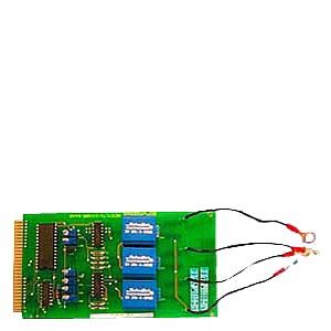
Line-voltage sensing modules
- Заказные данные (1)
- Информационные материалы
Информационные материалы
The line-voltage sensing submodule is an optional module for line-voltage sensing and correction.
The line-voltage sensing submodule is plugged from the front into the enclosure of the central interface module. The slot is located in the busbar area. If the line-voltage sensing submodule is not used, the opening is sealed by the busbar cover. If the line-voltage sensing submodule is used, the cover is used for shock-hazard protection.
Дизайн
- Connection of phases L1, L2, L3 and the neutral conductor via Teflon-coated cable
- Board connector for central interface module
Функции
Line voltage compensation
This function is required if the output power is to be corrected automatically in the case of strong line voltage fluctuations.
To implement this function, a line-voltage sensing submodule must be plugged in to at least one central interface module in a network of several HCS724I heater controllers.
The correction factors are calculated and transferred to the PROFIBUS DP master. The DP master then distributes these values to all HCS724I DP slaves.
Voltage measurement for enhanced diagnostics
To enable voltage values to be measured for enhanced diagnostics, a line-voltage sensing submodule is required for each central interface module.
The determined voltage value is used for detecting faults in emitters connected in parallel.
Note:
The central interface module is only supplied from the factory without a line-voltage sensing submodule. If you want to compensate for line voltage fluctuations, you must order both modules (line-voltage sensing submodule and central interface module) and connect them together on site.
Технические данные
Order number
6ES7171-1XX00-6AA0
HCS Voltage compensation NE724
General information
Product designation
Line voltage compensation NE724
Installation type/mounting
Mounting position
vertical
Type of ventilation
Self ventilation or forced ventilation
Supply voltage
Design of the power supply
Power supply via central connection
Resistance thermometer (RTD)
● Design of electrical connection for supply voltage
4 connecting cables with ring cable lug
Interfaces
Interfaces/bus type
system interface
Integrated Functions
Measuring functions
● Voltage measurement
Yes
● Current measurement
No
Measuring inputs for voltage
— Operational voltage at 50 Hz AC, min.
187 V
— Operational voltage at 50 Hz AC, max.
264 V
— Operational voltage at 60 Hz AC, min.
187 V
— Operational voltage at 60 Hz AC, max.
264 V
— Relative measuring accuracy voltage
3 %
— Operating frequency, min.
50 Hz
— Operating frequency, max.
60 Hz
— Design of electrical connection at the measuring inputs for voltage
Ring cable lug M6
Isolation
Overvoltage category
III
EMC
EMC interference emission
Limit value class A to EN 55011 group 1
Electrostatic discharge acc. to IEC 61000-4-2
4 kV contact discharge / 8 kV air discharge
Field-related interference acc. to IEC 61000-4-3
10 V/m (80 ... 1 000 MHz), 3 V/m (1.4 ... 2.0 GHz), 1 V/m (2.0 ... 2.7 GHz)
Conducted interference due to burst acc. to IEC 61000-4-4
2 kV voltage supply cables / 2 kV signal cables
Conducted interference due to surge acc. to IEC 61000-4-5
on power supply and signal cables: 1 kV symmetrical, 2 kV unsymmetrical
Conducted interference due to high-frequency radiation acc. to IEC 61000-4-6
10 V (0.15 ... 80 MHz)
Degree and class of protection
IP degree of protection
IP20
Standards, approvals, certificates
Certificate of suitability
CE, KCC
Degree of pollution
2
Device tag according to DIN EN 81346-2
T
Ambient conditions
Ambient temperature during operation
● min.
0 °C
● max.
55 °C
Ambient temperature during storage/transportation
● Storage, min.
-40 °C
● Storage, max.
70 °C
● Transportation, min.
-40 °C
● Transportation, max.
70 °C
Air pressure acc. to IEC 60068-2-13
● Operation, min.
860 hPa
● Operation, max.
1 080 hPa
● Storage, min.
660 hPa
● Storage, max.
1 080 hPa
● Installation altitude above sea level, max.
2 000 m
Relative humidity
● at 25 °C, max.
95 %
Vibrations
● Vibration resistance during operation acc. to IEC 60068-2-6
10 ... 58 Hz / 0.15 mm, 58 ... 150 Hz / 1 g
● Vibration resistance during storage acc. to IEC 60068-2-6
5 ... 9 Hz / 3.5 mm, 9 ... 500 Hz / 1 g
Shock testing
● Shock resistance acc. to IEC 60068-2-27
15 g / 11 ms / 3 shocks/axis
● Shock resistance acc. to IEC 60068-2-29
25 g / 6 ms / 1 000 shocks/axis
Dimensions
Width
86 mm
Height
22 mm
Depth
160 mm