
- Каталог оборудования Siemens
- Каталог продуктов Siemens Industry
- Приводная техника
- Преобразователи
- Стандартные преобразователи
- Общая информация о базовых преобразователях SINAMICS V
- Преобразователи частоты общего назначения SINAMICS G
- Преобразователи частоты SINAMICS G110
- Компактные преобразователи SINAMICS G120C
- Преобразователи для насосов, вентиляторов,компрессоров SINAMICS G120P
- Стандартные преобразователи SINAMICS G120
- SINAMICS G110M distributed inverters
- Highlights
- Introduction
- SINAMICS G110M distributed frequency inverters
- CU240M Control Units
- CU240M Control Units
- PM240M Power Modules
- Repair switch
- Recommended line-side power components
- Braking resistors
- 24 V DC power supply
- Compatible SIMOTICS motors
- Compatible SIMOGEAR geared motors
- Supplementary system components
- Spare Parts Kit
- Selection and engineering tools
- Services and documentation
- Преобразователь частоты SINAMICS G110D для распределенной периферии
- Преобразователи частоты SINAMICS G120D
- Преобразователи SINAMICS G130 формат шасси
- Преобразователь частоты SINAMICS G150 шкафного исполнения
- SINAMICS G180
- Высокопроизводительные преобразователи SINAMICS S
- MICROMASTER
- SIPLUS POSMO A
- SIMODRIVE POSMO
- LOHER DYNAVERT Drive System
- Преобразователи на среднее напряжение
- Преобразователи постоянного тока
- Стандартные преобразователи
- Двигатели переменного тока
- Generators
- Мотор-редукторы
- Flender Gear Units
- Couplings
- Инструментальное программное обеспечение
- Дополнительные компоненты
- Преобразователи
- Техника автоматизации
- Energy
- Автоматизация и безопасность зданий
- Низковольтная коммутационная техника
- Технология безопасности
- Системные решения и продукты для отраслей
- Сервис
- Приводная техника
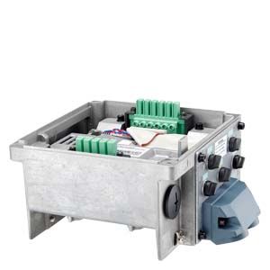
CU240M Control Units
- Заказные данные (24)
- Информационные материалы
Информационные материалы
The Control Unit performs closed-loop control functions for the inverter. In addition to the primary closed-loop control function, it has many additional functions that can be adapted to the particular application through parameterization.
The Control Units are available in two versions for connection to 400 V 3 AC and 24 V DC – screw-type or plug-in. The version in USS fieldbus communication is only available as screw-type. The differences between the screw-type and plug-in versions are presented in the following pictures:

SINAMICS G110M CU240M PN Control Unit cable gland
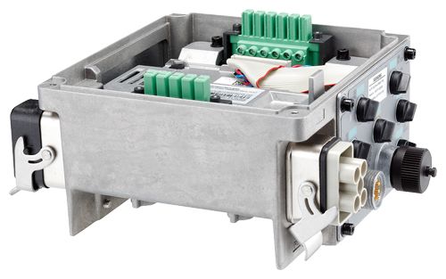
SINAMICS G110M CU240M PN Control Unit plug-in
Several Control Units are available in different versions:
Control Unit
Communications via
Connection system
For motor frame sizes
CU240M Control Unit, screw-type
CU240M
USS, Modbus RTU
Screw-type version
71, 80/90, 100/112
CU240M AS‑i Control Unit, screw-type
CU240M AS‑i
AS-Interface
Screw-type version
71, 80/90, 100/112
CU240M AS‑i Control Unit, plug-in
CU240M AS‑i
AS-Interface
Plug-in version
71, 80/90, 100/112
CU240M DP Control Unit, screw-type
CU240M DP
PROFIBUS
Screw-type version
71, 80/90, 100/112
CU240M DP Control Unit, plug-in
CU240M DP
PROFIBUS
Plug-in version
71, 80/90, 100/112
CU240M PN Control Unit, screw-type
CU240M PN
PROFINET, EtherNet/IP
Screw-type version
71, 80/90, 100/112
CU240M PN Control Unit, plug-in
CU240M PN
PROFINET, EtherNet/IP
Plug-in version
71, 80/90, 100/112
Safety Integrated functions
The safety function "Safe Torque Off" (STO 1)) (certified according to IEC 61508 SIL 2 and EN ISO 13849‑1 PL d and Category 3) is already integrated into the basic versions of the CU240M series (CU240M, CU240M DP and CU240M PN). It prevents active movement of the drive. It can be activated either over PROFIsafe or over the safety input.
Existing systems in particular can be simply updated with safety technology without the need to change the motor or mechanical system.
1) Available for firmware version V4.7 or higher
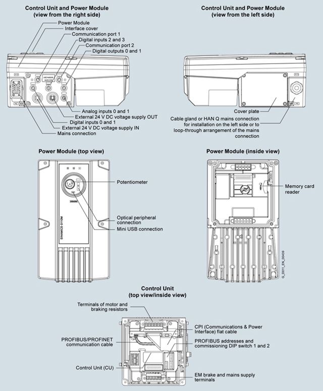
Дизайн
Интеграция

Connection diagram for CU240M Control Units
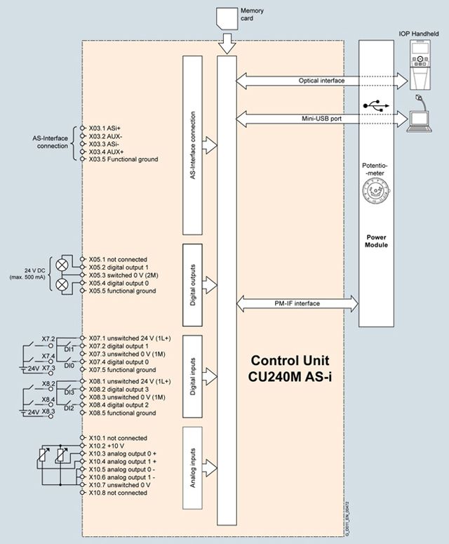
Connection diagram for CU240M AS-i Control Units
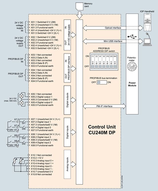
Connection diagram for CU240M DP Control Units

Connection diagram for CU240M PN Control Units
Технические данные
Control Unit
CU240M
CU240M AS-i
CU240M AS-i
CU240M PROFIBUS
CU240M PROFIBUS
CU240M PROFINET
CU240M PROFINET
Screw-type version
Screw-type version
Plug-in version
Screw-type version
Plug-in version
Screw-type version
Plug-in version
6SL3544...
-0LB02-1BA0
-0MB02-1BA0
-0NB02-1BA0-0LB02-1MA0
-0MB02-1MA0
-0NB02-1MA0-0TB02-1MA0
-0PB02-1MA0
-0QB02-1MA0-0LB02-1PA0
-0MB02-1PA0
-0NB02-1PA0-0TB02-1PA0
-0PB02-1PA0
-0QB02-1PA0-0LB02-1FA0
-0MB02-1FA0
-0NB02-1FA0-0TB02-1FA0
-0PB02-1FA0
-0QB02-1FA0Electrical specifications
Operating voltage
External 24 V DC ± 15 %
power supply with protective extra low voltage PELV acc. to EN 61800-5-1 must be used.Current consumption 1)
(from the 24 V DC supply)
- With Power Module frame size FSA
235 mA
290 mA
290 mA
235 mA
235 mA
290 mA
290 mA
- With Power Module frame size FSB
235 mA
290 mA
290 mA
235 mA
235 mA
290 mA
290 mA
Interfaces
Digital inputs
(non-isolated)
4 programmable, PNP, SIMATIC compatible
- Optionally parameterizable as safe inputs
1
Analog inputs
(0 ... 10 V or 0 ... 20 mA with 12-bit resolution)
2
Digital outputs
24 V DC (0 ... 0.5 A)
2, programmable
Bus interface
USS
AS-Interface
AS-Interface
PROFIBUS DP
PROFIBUS DP
PROFINET
PROFINET
- Fieldbus protocols
USS
Modbus RTUAS-Interface
AS-Interface
PROFIBUS DP incl. PROFIsafe
PROFIBUS DP incl. PROFIsafe
PROFINET incl. PROFIsafe
EtherNet/IPPROFINET incl. PROFIsafe
EtherNet/IP- Profiles
–
3.0
3.0
PROFIdrive
PROFIdrive
PROFIdrive
PROFIenergyPROFIdrive
PROFIenergyPTC/KTY interface
(connection via Power Module)
✓
- Motor temperature sensor
1 input, sensors that can be connected: PTC, KTY or bimetal
Control of a mechanical motor brake
(connection via the Control Unit)
✓
Slot for SINAMICS memory card (SD card)
✓
Commissioning interface (mini USB)
✓
Safety functions
Integrated safety functions 2)
acc. to IEC 61508 SIL 2 and EN ISO 13849‑1 PL d and Category 3
Safe Torque Off (STO)
Open-loop/closed-loop control techniques
V/f linear/quadratic/parameterizable
✓
V/f with flux current control (FCC)
✓
Vector control, sensorless
✓
Torque control, sensorless
✓
Software functions
Fixed frequencies
✓
Signal interconnection with BICO technology
✓
Automatic restart after line supply failure or operational fault
✓
Slip compensation
✓
Free function blocks (FFB) for logical and arithmetic operations
✓
Ramp smoothing
✓
Selectable drive data sets
✓ (4)
Selectable command data sets (CDS) (manual/auto)
✓ (4)
Flying restart
✓
JOG
✓
Cyclic recording of ramp-up and ramp-down
✓
Technology controller (PID)
✓
Quick stop
✓
Limit switch logic
✓
Thermal motor protection
✓
Thermal inverter protection
✓
Setpoint input
✓
Motor identification
✓
Motor holding brake
✓
Mechanical specifications and ambient conditions
Degree of protection 3)
IP66/UL Type 3
IP66/UL Type 12 (with wall mounting kit)
IP66/UL Type 3
IP66/UL Type 12 (with wall mounting kit)
IP65/UL Type 3
IP65/UL Type 12 (with wall mounting kit)
IP66/UL Type 3
IP66/UL Type 12 (with wall mounting kit)
IP65/UL Type 3
IP65/UL Type 12 (with wall mounting kit)
IP66/UL Type 3
IP66/UL Type 12 (with wall mounting kit)
IP65/UL Type 3
IP65/UL Type 12 (with wall mounting kit)
Operating temperature
-10 ... +55 ℃
(14 ... 131 °F)Air temperature
-40 ... +70 °C
(40 ... 158 °F)Relative humidity
<95 % RH,
condensation not permissibleDimensions
- Width
205 mm (8.07 in)
- Height
105 mm (4.13 in)
- Depth
171 mm (6.73 in)
Weight, approx.
1.75 kg (3.86 lb)
1.85 kg (4.08 lb)
1.85 kg (4.08 lb)
1.85 kg (4.08 lb)
1.85 kg (4.08 lb)
1.85 kg (4.08 lb)
1.85 kg (4.08 lb)
1) The current consumption of connected sensors (total, max. 200 mA) as well as the current drawn from the digital outputs (total, max. 500 mA).
2) Available for firmware version V4.7 or higher
3) Applies to Power Modules and Control Units in mounted state.