
- Каталог оборудования Siemens
- Каталог продуктов Siemens Industry
- Приводная техника
- Техника автоматизации
- Системы автоматизации
- Системы визуализации SIMATIC HMI
- Системы идентификации
- Промышленные коммуникации SIMATIC NET
- Промышленные аппараты управления SIRIUS
- Промышленные информационные технологии
- Управление на базе РС
- Системы управления процессом
- Контрольно-измерительные приборы
- Анализаторы процесса
- Блоки питания SITOP
- Продукты для специальных требований
- Energy
- Автоматизация и безопасность зданий
- Низковольтная коммутационная техника
- Технология безопасности
- Системные решения и продукты для отраслей
- Сервис
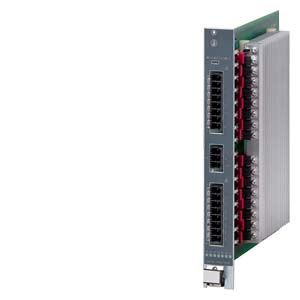
Power Output Module (POM)
- Заказные данные (3)
- Аксессуары (6)
- Информационные материалы
Информационные материалы
The power output modules (POMs) are an essential component of the SIPLUS HCS4200 heating control system.
Up to 24 power output modules can be operated on one CIM, split over two racks.There are three power output module versions:
- POM4220 Lowend
- POM4220 mid-range
- POM4220 mid-range phase control
Дизайн
Power output module POM4220 Lowend
- 16 outputs for connecting resistive loads.
- A current of up to 6.3 A can be used per output.
- The two phases and neutral conductor are connected via a 3-pin connector (mating connectors are included in the scope of delivery).
- The heat emitters are connected via two 8-pin connectors (mating connectors are included in the scope of delivery).
- One fuse per output for supply circuit.
- Module simply slides into the rack.
- Heat dissipation via an optional fan module at the top of the rack (for 4 POM4220).
- Attachment is with one screw at the bottom and another one at the top.
- Three diagnostics LEDs for displaying module faults.
- Sixteen diagnostics LEDs for displaying errors at the outputs.
Power output module POM4220 Midrange
- 12 outputs for connecting resistive loads.
- A current of up to 12 A can be used per output.
- The two phases and neutral conductor are connected via a 3-pin connector (mating connectors are included in the scope of delivery).
- The heat emitters are connected via two 6-pin connectors (mating connectors are included in the scope of delivery).
- One fuse per output for supply circuit.
- Module simply slides into the rack.
- Heat dissipation via an optional fan module at the top of the rack (for 4x POM4220).
- Attachment is with one screw at the bottom and another one at the top.
- Three diagnostics LEDs for displaying module faults.
- 12 diagnostics LEDs for displaying errors at the outputs
Power output module POM4220 Midrange phase control
- 12 outputs for connecting resistive loads.
- A current of up to 16 A can be used per output.
- The two phases and neutral conductor are connected via a 3-pin connector (mating connectors are included in the scope of delivery).
- The heat emitters are connected via two 6-pin connectors (mating connectors are included in the scope of delivery).
- One fuse per output for supply circuit.
- Module simply slides into the rack.
- Heat dissipation via an optional fan module at the top of the rack (for 4x POM4220).
- Attachment is with one screw at the bottom and another one at the top.
- Three diagnostics LEDs for displaying module faults.
- 12 diagnostics LEDs for displaying errors at the outputs
Функции
Power switching elements
- Power triacs
- Protection of triacs and opto-triacs against overvoltages by Transil diodes
- Transfer of the diagnostics information to the central interface module (CIM)
Control modes
Power output module POM4220 Lowend
- Half-wave control:
This is the control type in normal operation. At every zero crossover, the output is controlled depending on the parameterized setpoint value. The control variable is set to values between 0 and 100%.
Power output module POM4220 Midrange
- Half-wave control:
This is the control type in normal operation. At every zero crossover, the output is controlled depending on the parameterized setpoint value. The controller outputs are set in values from 0 to 100 %. - Soft start:
Phase control is executed for a limited time in order to achieve a gradual warming of the heating elements (e.g. for shortwave infrared sources). Switches to half-wave control when the time has expired. The control variable is set to values between 0 and 100%.
Power output module POM4220 Midrange
- Half-wave control:
This is the control type in normal operation. At every zero crossover, the output is controlled depending on the parameterized setpoint value. The control variable is set to values between 0 and 100%. - Soft start:
Phase control is executed for a limited time in order to achieve a gradual warming of the heating elements (e.g. for shortwave infrared sources). Switches to half-wave control when the time has expired. The control variable is set to values between 0 and 100%. - Phase control:
Phase control is executed permanently in order to achieve even heat dissipation and avoid disruptive emitter flickering with low setpoints. Phase control can sometimes cause EMC interference on the power supply lines which then has to be filtered on the system side.
Output power
Power output module POM4220 Lowend
- 16 power outputs of 230 V each (8 outputs per phase)
- Switching capacity per output: Max. 1449 W at 230 V.
Caution: Short-wave halogen or infrared emitters, so-called flash emitters, have a high switch-on current due to their relatively low cold resistance. This switch-on current can be a multiple of the rated current especially during the initial half-waves. This can lead to the fuse being triggered. There is a limit to a switching power of 750 W when using flash emitters. - Switching capacity per power output module: Max. 16100 W at 230 V
Power output module POM4220 Midrange
- 12 power outputs of 230 V/277 V each (6 outputs per phase)
- Switching power per output: max. 2760 W at 230 V or 3324 W at 277 V.
Caution: Short-wave halogen or infrared emitters, so-called flash emitters, have a high switch-on current due to their relatively low cold resistance. This switch-on current can be a multiple of the rated current especially during the initial half-waves. This can lead to the fuse being triggered. There is a limit to a switching power of 1600 W when using flash emitters. - Switching capacity per power output module: Max. 23 000 W at 230 V or 27 700 W at 277 V.
Power output module POM4220 Midrange phase control
- 12 power outputs of 230 V/277 V each (6 outputs per phase)
- Switching capacity per output: max. 3680 W at 230 V or 4432 W at 277 V.
Caution: Short-wave halogen or infrared emitters, so-called flash emitters, have a high switch-on current due to their relatively low cold resistance. This switch-on current can be a multiple of the rated current especially during the initial half-waves. This can lead to the fuse being triggered. There is a limit to a switching power of 1600 W when using flash emitters. - Switching capacity per power output module: max. 23,000 W at 230 V or 27,700 W at 277 V.
Ventilation
- A fan module can be optionally mounted at the top of the rack so that 4 POMs can be ventilated and controlled dependent on the internal temperature.
Temperature monitoring
- An NTC thermistor is installed in the device to monitor the internal temperature. An alarm threshold is defined for the internal temperature. The following reactions are triggered when the threshold is overshot:
- Signal to the higher-level controller.
- The outputs are deactivated - regardless of which output response was configured for the error.
Diagnostic options
Implicit diagnostics functions are provided as standard to detect the following faults (diagnostics cycle does not affect the heating power):
- Leading fuse defective / triac at high resistance (exception: setpoint 0%)
- Triac failure (exception: setpoint 100%)
- Heating element cable is defective (short-circuit and interruption)
- Load defective (short-circuit and interruption)
Технические данные
Order number
6BK1942-2AA00-0AA0
6BK1942-2CA00-0AA0
6BK1942-2CA00-0AA1
General information
Product brand name
SIPLUS
Product designation
POM4220 Lowend
POM4220 Midrange
POM4220 mid-range phase control
Type of control of heat emitters
Half-wave control
Half-wave control and soft start
Half-wave control, phase control and soft start
Installation type/mounting
Mounting type
Screw mounting to rack
Mounting position
vertical
Type of ventilation
Self ventilation or forced ventilation
Supply voltage
Type of supply voltage
AC
Rated value (AC)
230 V
277 V
Relative negative tolerance
10 %
25 %
Relative positive tolerance
10 %
8 %
Line frequency
● Rated value 1
50 Hz
● Rated value 2
60 Hz
● Relative symmetrical tolerance
5 %
Mains buffering
● Recovery time after power failure, typ.
1 s
Resistance thermometer (RTD)
● Design of electrical connection for supply voltage
Connector, 3-pole with spring-loaded connection
Connector, 3-pin
— Connectable conductor cross-sections, solid
1x (0.2 ... 10 mm²)
1x (0.75 ... 16 mm²)
— Connectable conductor cross-sections, finely stranded with wire end processing
1x (0.25 ... 6 mm²)
1x (0.75 ... 16 mm²)
— Connectable conductor cross-sections for AWG cables
1x (24 ... 8)
1x (18 ... 4)
Power supply for the electronics
Design of the power supply
Power supply via rack
Power
Active power input, max.
1 W
Power electronics
Type of load
Ohmic load
Power capacity, max.
16.1 kW
27.7 kW
● for star connection with fan at 40 °C, max.
16.1 kW
27.7 kW
● for star connection without fan at 40 °C, max.
7.3 kW
9 kW
Switching capacity current per phase, max.
35 A
50 A
Heating power
● Number of digital outputs
16
12
● Number of heat emitters per output, max.
1
● Output voltage for heating power
230 V
277 V
● Power carrying capacity per output, min.
100 W
● Power carrying capacity per output, max.
1 449 W
3 324 W
4 432 W
— for heating elements with high inrush current, max.
750 W
1 600 W
● Output current for heating power
6.3 A
12 A
16 A
● Melting I2t value
57 A²·s
68 A²·s
120 A²·s
● Design of short-circuit protection per output
Safety fuse 6.3 A
Fuse 16 A
● Design of overvoltage protection
Transil Diode
Integration and conversion time/resolution per channel
● Design of electrical connection at output for heating and fan
Connector, 8-pin with tension spring connection
Connector, 6-pole with spring-loaded connection
— Connectable conductor cross-sections, solid
1x (0.2 ... 10 mm²)
— Connectable conductor cross-sections, finely stranded with wire end processing
1x (0.25 ... 6 mm²)
— Connectable conductor cross-sections for AWG cables, stranded
1x (24 ... 8)
Interfaces
Interfaces/bus type
system interface
Interrupts/diagnostics/status information
Number of status displays
19
15
LED status display
LED green = ready, LED yellow = heating on/off, LED red = error display, LED red = error for each channel
Diagnostics function
Voltage diagnostics
Diagnostic messages
● Wire-break
Yes
● Fuse blown
Yes
● Heat emitter defect
Yes
Integrated Functions
Monitoring functions
● Temperature monitoring
Yes
● Type of temperature monitoring
NTC thermistor
Potential separation
Design of electrical isolation
Optocoupler and/or protective impedance between main circuit and PELV
between the outputs
No
Isolation
Overvoltage category
III
EMC
EMC interference emission
Limit value in accordance with IEC 61000-6-4:2007 + A1:2011
Electrostatic discharge acc. to IEC 61000-4-2
4 kV contact discharge / 8 kV air discharge
Field-related interference acc. to IEC 61000-4-3
10 V/m (80 ... 1 000 MHz), 3 V/m (1.4 ... 2.0 GHz), 1 V/m (2.0 ... 2.7 GHz)
Conducted interference due to burst acc. to IEC 61000-4-4
2 kV power supply lines, 2 kV load lines
Conducted interference due to surge acc. to IEC 61000-4-5
Supply and load lines: 1 kV symmetrical, 2 kV asymmetrical
Conducted interference due to high-frequency radiation acc. to IEC 61000-4-6
10 V (0.15 ... 80 MHz)
Degree and class of protection
IP degree of protection
IP20
Standards, approvals, certificates
Degree of pollution
2
Device tag according to DIN EN 81346-2
Q
Ambient conditions
Ambient temperature during operation
● min.
0 °C
● max.
55 °C
Ambient temperature during storage/transportation
● Storage, min.
-25 °C
● Storage, max.
70 °C
● Transportation, min.
-25 °C
● Transportation, max.
70 °C
Air pressure acc. to IEC 60068-2-13
● Operation, min.
860 hPa
● Operation, max.
1 080 hPa
● Storage, min.
660 hPa
● Storage, max.
1 080 hPa
● Installation altitude above sea level, max.
2 000 m
Relative humidity
● Operation at 25 ℃, max.
95 %
● Operation at 50 ℃, max.
50 %; 95 % at 25 °C, decreasing linearly to 50 % at 50 °C
Vibrations
● Vibration resistance during operation acc. to IEC 60068-2-6
10 ... 58 Hz / 0.075 mm, 58 ... 150 Hz / 1 g
● Vibration resistance during storage acc. to IEC 60068-2-6
5 ... 8.5 Hz / 3.5 mm, 8.5 ... 500 Hz / 1 g
Shock testing
● Shock resistance during operation acc. to IEC 60068-2-27
15 g / 11 ms / 3 shocks/axis
● Shock resistance during storage acc. to IEC 60068-2-29
25 g / 6 ms / 1 000 shocks/axis
Dimensions
Width
36 mm
Height
285 mm
Depth
281 mm
Дополнительно
The following accessories are available for the power output module:
- Fuse 6.3 A/250 V (set with 50 fuses) as spare part (for POM4220 Lowend)
- Fuse 16 A/500 V (set with 50 fuses) as spare part (for POM4220 Midrange)
- Fuse 16 A/500V (set with 50 fuses) as spare part (for POM4220 Midrange)
- 3-pin connector set (block with 10 connectors) for connecting the incoming supply (for POM4220 Lowend)
- 3-pin connector set (block with 10 connectors) for connecting the incoming supply (for POM4220 Midrange)
- Connector set 8-pin (block with 10 connectors) for connecting the heat emitters
- Connector set 6-pin (block with 10 connectors) for connecting the heat emitters