
- Каталог оборудования Siemens
- Каталог продуктов Siemens Industry
- Приводная техника
- Техника автоматизации
- Системы автоматизации
- Системы визуализации SIMATIC HMI
- Системы идентификации
- Промышленные коммуникации SIMATIC NET
- Промышленные аппараты управления SIRIUS
- Промышленные информационные технологии
- Управление на базе РС
- Системы управления процессом
- Контрольно-измерительные приборы
- Анализаторы процесса
- Блоки питания SITOP
- Продукты для специальных требований
- Energy
- Автоматизация и безопасность зданий
- Низковольтная коммутационная техника
- Технология безопасности
- Системные решения и продукты для отраслей
- Сервис
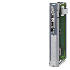
Central Interface Module (CIM)
- Заказные данные (2)
- Аксессуары (4)
- Информационные материалы
Информационные материалы
The central interface module (CIM) is the intelligent processor module of the SIPLUS HCS4200 heating control system.
Дизайн
- Module encapsulated in metal enclosure
- 3 LEDs for: Operating state (green), heating on (yellow) and fault (red)
- PROFINET interface (up to 100 MBaud) with double switch
- Differential serial bus interface for the power output modules (POMs)
- Secured with 6 screws to the left side of the rack
- Power supply for the power output modules and the fan modules of the heating control system
Функции
Communication
PROFINET
- Import of the parameter settings from the higher-level controller
- Transfer of the diagnostic information to the higher-level controller
- Serial bus (internal)
- Control and monitoring of max. 192 power output channels
Performance features
- Calculation of manipulated variables of power output channels
- Setpoints can be adjusted from 0 % to 100 % in increments of 1 %
- Uniform load distribution over all power output channels and over all the SIPLUS HCS4200 heating controllers operated in the group
- Simple adaptation to any production process through the selection of operating modes
- Diagnostic functions
- Evaluation of diagnostics information from connected power output modules
- Automatic detection of the line frequency
Технические данные
Order number
6BK1942-1AA00-0AA0
6BK1942-1BA00-0AA0
6BK1942-1CA00-0AA0
HCS CIM4210 PROFINET
HCS CIM4210 PROFIBUS
HCS CIM4210 EtherNet/IP
General information
Product brand name
SIPLUS
Product designation
CIM4210 PROFINET
CIM4210 PROFIBUS
CIM4210 EtherNet/IP
Installation type/mounting
Mounting type
Screw mounting to rack
Mounting position
vertical
Type of ventilation
Forced ventilation
Supply voltage
Type of supply voltage
DC
Rated value (DC)
24 V
Relative negative tolerance
20 %
Relative positive tolerance
20 %
Resistance thermometer (RTD)
● Design of electrical connection for supply voltage
Connector 2x 2-pin with tension spring connection
— Connectable conductor cross-sections, solid
1x (0.2 ... 2.5 mm²)
— Connectable conductor cross-sections, finely stranded with wire end processing
1x (0.2 ... 2.5 mm²)
— Connectable conductor cross-sections for AWG cables
1x (26 ... 12)
Power
Active power input
3 W
Hardware configuration
Type of power output connectable
POM4220
Slots
● Number of slots
1
Interfaces
Interfaces/bus type
PROFINET IO
PROFIBUS DP
EtherNet/IP
PROFINET IO
● Transmission rate, max.
100 Mbit/s
● Design of electrical connection of PROFINET interface
2 x RJ45
PROFIBUS DP
● Transmission rate, max.
12 Mbit/s
● Design of electrical connection of PROFIBUS interface
9-pin sub D socket
EtherNet/IP
● Transmission rate, max.
100 Mbit/s
● Design of EtherNet/IP interface electrical connection
2 x RJ45
Protocols
Supports protocol for PROFINET IO
Yes
No
PROFIBUS DP
No
Yes
No
Further protocols
● EtherNet/IP
Yes
Interrupts/diagnostics/status information
Number of status displays
3
LED status display
LED green = ready, LED yellow = heating on/off, LED red = error display
Isolation
Overvoltage category
III
EMC
EMC interference emission
Limit value in accordance with IEC 61000-6-4:2007 + A1:2011
Electrostatic discharge acc. to IEC 61000-4-2
4 kV contact discharging, 8 kV air discharging
Field-related interference acc. to IEC 61000-4-3
10 V/m (80 ... 1 000 MHz), 3 V/m (1.4 ... 2.0 GHz), 1 V/m (2.0 ... 2.7 GHz)
Conducted interference due to burst acc. to IEC 61000-4-4
2 kV power supply lines, 2 kV PROFINET cables
2 kV power supply lines / 2 kV PROFIBUS cables
2 kV power supply lines, 2 kV PROFINET cables
Conducted interference due to surge acc. to IEC 61000-4-5
DC supply lines: 0.5 kV symmetric and unsymmetric PROFINET cables: 1 kV unsymmetric
DC supply lines: 0.5 kV symmetrical and asymmetrical, PROFIBUS lines: 1 kV asymmetrical
DC supply lines: 0.5 kV symmetric and unsymmetric PROFINET cables: 1 kV unsymmetric
Conducted interference due to high-frequency radiation acc. to IEC 61000-4-6
10 V (0.15 ... 80 MHz)
Degree and class of protection
IP degree of protection
IP20
Standards, approvals, certificates
Degree of pollution
2
Device tag according to DIN EN 81346-2
K
Ambient conditions
Ambient temperature during operation
● min.
0 °C
● max.
55 °C
Ambient temperature during storage/transportation
● Storage, min.
-25 °C
● Storage, max.
70 °C
● Transportation, min.
-25 °C
● Transportation, max.
70 °C
Air pressure acc. to IEC 60068-2-13
● Operation, min.
860 hPa
● Operation, max.
1 080 hPa
● Storage, min.
660 hPa
● Storage, max.
1 080 hPa
● Installation altitude above sea level, max.
2 000 m
Relative humidity
● Operation at 25 ℃, max.
95 %
● Operation at 50 ℃, max.
50 %; 95 % at 25 °C, decreasing linearly to 50 % at 50 °C
Vibrations
● Vibration resistance during operation acc. to IEC 60068-2-6
10 ... 58 Hz / 0.075 mm, 58 ... 150 Hz / 1 g
● Vibration resistance during storage acc. to IEC 60068-2-6
5 ... 8.5 Hz / 3.5 mm, 8.5 ... 500 Hz / 1 g
Shock testing
● Shock resistance during operation acc. to IEC 60068-2-27
15 g / 11 ms / 3 shocks/axis
● Shock resistance during storage acc. to IEC 60068-2-29
25 g / 6 ms / 1 000 shocks/axis
Dimensions
Width
43 mm
Height
285 mm
Depth
136 mm