
- Каталог оборудования Siemens
- Каталог продуктов Siemens Industry
- Приводная техника
- Техника автоматизации
- Системы автоматизации
- Системы визуализации SIMATIC HMI
- Системы идентификации
- Промышленные коммуникации SIMATIC NET
- Промышленные аппараты управления SIRIUS
- Промышленные информационные технологии
- Управление на базе РС
- Системы управления процессом
- Контрольно-измерительные приборы
- Анализаторы процесса
- Блоки питания SITOP
- Блоки питания серии SITOP lite
- SITOP compact
- Блоки питания серии LOGO!Power
- SITOP lite
- Блоки питания серии SITOP smart
- Модульные блоки питания SITOP
- SITOP modular, PSU8600 power supply system
- SITOP в исполнении SIMATIC
- Специальное исполнение и назначение
- Дополнительные компоненты
- Блоки бесперебойного питания DC-UPS
- Аксессуары
- Блоки питания заказного исполнения
- Семейство SIPLUS
- SIPLUS DC-UPS, бесперебойные источники питания
- Блоки питания для AS-интерфейса
- Техническая информация и проектирование
- SITOP power для AS-Interface
- Продукты для специальных требований
- Energy
- Автоматизация и безопасность зданий
- Низковольтная коммутационная техника
- Технология безопасности
- Системные решения и продукты для отраслей
- Сервис
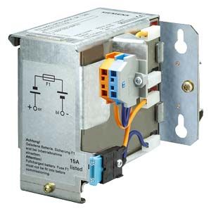
Battery modules DC UPS
- Заказные данные (5)
- Информационные материалы
Информационные материалы
Maintenance-free battery modules with 1.2 Ah up to 12 Ah (lead-gel accumulator) for ambient temperatures from 0 to +40 °C as well as high-temperature battery module with 2.5 Ah (pure-lead accumulator) for ambient temperatures of –40 °C to +60 °C. The battery modules are completely prewired with battery retainer and terminals. For longer buffer times, the battery modules can be connected in parallel. Mounting onto standard mounting rail or directly to the wall.
Технические данные
Order number
6EP1935-6MC01
6EP1935-6MD31
6EP1935-6MD11
6EP1935-6ME21
6EP1935-6MF01
Product
SITOP Battery module
SITOP Battery module
SITOP Battery module
SITOP Battery module
SITOP Battery module
Product type
Battery module 1.2 Ah
Battery module 2.5 Ah
Battery module 3.2 Ah
Battery module 7 Ah
Battery module 12 Ah
Charging current charging voltage
End-of-charge voltage at DC
● at -10 °C recommended
29 V
● at 0 °C recommended
28.6 V
● at 10 °C recommended
27.8 V
28.3 V
27.8 V
27.8 V
27.8 V
● at 20 °C recommended
27.3 V
27.9 V
27.3 V
27.3 V
27.3 V
● at 30 °C recommended
26.8 V
27.5 V
26.8 V
26.8 V
26.8 V
● at 40 °C recommended
26.6 V
27.2 V
26.6 V
26.6 V
26.6 V
● at 50 °C recommended
26.3 V
26.8 V
26.3 V
26.3 V
26.3 V
● at 60 °C recommended
26.4 V
Permissible charging current, max.
0.3 A
5 A
0.8 A
1.75 A
3 A
Rated voltage Vout DC
24 V
24 V
24 V
24 V
24 V
Safety
Short-circuit protection
Battery fuse 7.5 A/32 V (solid-state circuitry blade-type fuse + support)
Battery fuse 15 A/32 V (solid-state circuitry blade-type fuse + support)
Battery fuse 15 A/32 V (solid-state circuitry blade-type fuse + support)
Battery fuse 20 A/32 V (solid-state circuitry blade-type fuse + support)
Battery fuse 20 A/32 V (solid-state circuitry blade-type fuse + support)
Design of the overload protection
Valve control
Valve control
Valve control
Valve control
Valve control
Safety
Protection class
Class III
Class III
Class III
Class III
Class III
CE mark
Yes
Yes
Yes
Yes
Yes
UL/cUL (CSA) approval
cURus-Recognized (UL 1778, CSA C22.2 No. 107.1), File E219627
cURus-Recognized (UL 1778, CSA C22.2 No. 107.1), File E219627
cURus-Recognized (UL 1778, CSA C22.2 No. 107.1), File E219627
cURus-Recognized (UL 1778, CSA C22.2 No. 107.1), File E219627
cURus-Recognized (UL 1778, CSA C22.2 No. 107.1), File E219627
Marine approval
GL, ABS
GL, ABS
GL, ABS
GL, ABS
GL, ABS
Degree of protection (EN 60529)
IP00
IP00
IP00
IP00
IP00
Operating data note
Operating data note
For storage, mounting and operation of lead-acid batteries, the relevant DIN/VDE regulations or country-specific regulations (e.g. VDE 0510 Part 2/EN 50272-2) must be observed. You must ensure that the battery site is sufficiently ventilated. Possible sources of ignition must be at least 50 cm away.
For storage, mounting and operation of lead-acid batteries, the relevant DIN/VDE regulations or country-specific regulations (e.g. VDE 0510 Part 2/EN 50272-2) must be observed. You must ensure that the battery site is sufficiently ventilated. Possible sources of ignition must be at least 50 cm away.
For storage, mounting and operation of lead-acid batteries, the relevant DIN/VDE regulations or country-specific regulations (e.g. VDE 0510 Part 2/EN 50272-2) must be observed. You must ensure that the battery site is sufficiently ventilated. Possible sources of ignition must be at least 50 cm away.
For storage, mounting and operation of lead-acid batteries, the relevant DIN/VDE regulations or country-specific regulations (e.g. VDE 0510 Part 2/EN 50272-2) must be observed. You must ensure that the battery site is sufficiently ventilated. Possible sources of ignition must be at least 50 cm away.
For storage, mounting and operation of lead-acid batteries, the relevant DIN/VDE regulations or country-specific regulations (e.g. VDE 0510 Part 2/EN 50272-2) must be observed. You must ensure that the battery site is sufficiently ventilated. Possible sources of ignition must be at least 50 cm away.
Ambient temperature
● during operation
-15 ... +50 °C
-40 ... +60 °C
-15 ... +50 °C
-15 ... +50 °C
-15 ... +50 °C
● during transport
-20 ... +50 °C
-40 ... +60 °C
-20 ... +50 °C
-20 ... +50 °C
-20 ... +50 °C
● during storage
-20 ... +50 °C
-40 ... +60 °C
-20 ... +50 °C
-20 ... +50 °C
-20 ... +50 °C
Relative temporary capacity loss at 20 °C in a month typical
3 %
3 %
3 %
3 %
3 %
Service life
Service life of energy storage
● typical remark
capacity falls to 50 % of original capacity
capacity falls to 50 % of original capacity
capacity falls to 50 % of original capacity
capacity falls to 50 % of original capacity
capacity falls to 50 % of original capacity
● at 20 °C typical
4 y
10 y
4 y
4 y
4 y
● at 30 °C typical
2 y
7 y
2 y
2 y
2 y
● at 40 °C typical
1 y
3 y
1 y
1 y
1 y
● at 50 °C typical
0.5 y
1.5 y
0.5 y
0.5 y
0.5 y
● at 60 °C typical
1 y
Ambient temperature during storage Note
Along with the storage and operating temperature, other factors such as the duration of the storage period and the charge status during storage have a decisive influence on the possible useful life. Batteries should therefore be stored as briefly as possible, always fully charged, and within the temperature range 0 to +20 °C.
Along with the storage and operating temperature, other factors such as the duration of the storage period and the charge status during storage have a decisive influence on the possible useful life. Batteries should therefore be stored as briefly as possible, always fully charged, and within the temperature range 0 to +20 °C.
Along with the storage and operating temperature, other factors such as the duration of the storage period and the charge status during storage have a decisive influence on the possible useful life. Batteries should therefore be stored as briefly as possible, always fully charged, and within the temperature range 0 to +20 °C.
Along with the storage and operating temperature, other factors such as the duration of the storage period and the charge status during storage have a decisive influence on the possible useful life. Batteries should therefore be stored as briefly as possible, always fully charged, and within the temperature range 0 to +20 °C.
Along with the storage and operating temperature, other factors such as the duration of the storage period and the charge status during storage have a decisive influence on the possible useful life. Batteries should therefore be stored as briefly as possible, always fully charged, and within the temperature range 0 to +20 °C.
Mechanics
Connection technology
spring-loaded terminals
spring-loaded terminals
spring-loaded terminals
spring-loaded terminals
spring-loaded terminals
Connection for power supply unit
1 screw terminal each for 0.08 ... 2.5 mm² for + BATT and - BATT
1 screw terminal each for 0.08 ... 2.5 mm² for + BATT and - BATT
1 screw terminal each for 0.08 ... 2.5 mm² for + BATT and - BATT
1 screw terminal each for 0.08 ... 4 mm² for + BATT and - BATT
1 screw terminal each for 0.08 ... 4 mm² for + BATT and - BATT
Product component belonging to
Accessories pack with solid-state circuitry fuse 7.5 A
Accessories pack with solid-state circuitry fuse 15 A
Accessories pack with solid-state circuitry fuse 15 A
Accessories pack with solid-state circuitry fuse 20 A and 30 A
Accessories pack with solid-state circuitry fuse 20 A and 30 A
Width of the enclosure
96 mm
265 mm
190 mm
186 mm
253 mm
Height of the enclosure
106 mm
151 mm
151 mm
168 mm
168 mm
Depth of the enclosure
108 mm
91 mm
82 mm
121 mm
121 mm
Installation width
116 mm
285 mm
210 mm
206 mm
273 mm
Installation height
126 mm
171 mm
171 mm
188 mm
188 mm
Weight, approx.
1.8 kg
3.8 kg
3.2 kg
6 kg
9 kg
Installation
snaps onto DIN rail EN 60715 35x7.5/15 or keyhole mounting for hooking in to M4 screws
snaps onto DIN rail EN 60715 35x15 or keyhole mounting for hooking in to M4 screws
snaps onto DIN rail EN 60715 35x7.5/15 or keyhole mounting for hooking in to M4 screws
can be screwed onto flat surface (keyhole mounting for hooking in to M4 screws)
can be screwed onto flat surface (keyhole mounting for hooking in to M4 screws)
Number of cells
12
12
12
12
12
Equipment marking acc. to DIN EN 81346-2
G
G
G
G
G
Other information
Specifications at rated input voltage and ambient temperature +25 °C (unless otherwise specified)
Specifications at rated input voltage and ambient temperature +25 °C (unless otherwise specified)
Specifications at rated input voltage and ambient temperature +25 °C (unless otherwise specified)
Specifications at rated input voltage and ambient temperature +25 °C (unless otherwise specified)
Specifications at rated input voltage and ambient temperature +25 °C (unless otherwise specified)