
- Каталог оборудования Siemens
- Каталог продуктов Siemens Industry
- Приводная техника
- Техника автоматизации
- Системы автоматизации
- Системы визуализации SIMATIC HMI
- Системы идентификации
- Промышленные коммуникации SIMATIC NET
- Промышленные аппараты управления SIRIUS
- Промышленные информационные технологии
- Управление на базе РС
- Системы управления процессом
- Контрольно-измерительные приборы
- Анализаторы процесса
- Блоки питания SITOP
- Блоки питания серии SITOP lite
- SITOP compact
- Блоки питания серии LOGO!Power
- SITOP lite
- Блоки питания серии SITOP smart
- Модульные блоки питания SITOP
- SITOP modular, PSU8600 power supply system
- SITOP в исполнении SIMATIC
- Специальное исполнение и назначение
- Дополнительные компоненты
- Блоки бесперебойного питания DC-UPS
- Аксессуары
- Блоки питания заказного исполнения
- Семейство SIPLUS
- SIPLUS DC-UPS, бесперебойные источники питания
- Блоки питания для AS-интерфейса
- Техническая информация и проектирование
- SITOP power для AS-Interface
- Продукты для специальных требований
- Energy
- Автоматизация и безопасность зданий
- Низковольтная коммутационная техника
- Технология безопасности
- Системные решения и продукты для отраслей
- Сервис
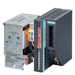
SITOP DC UPS
- Заказные данные (8)
- Информационные материалы
Информационные материалы
By combining a DC UPS module with at least one 24 V battery module and a SITOP power supply unit, longer power failures can be bridged without any interruption. Even if a greater buffering current is required, the DC UPS with maintenance-free lead battery provides optimum safety. It spans power failures up to several hours long and delivers up to 40 A.
Область применения
These battery modules that can be connected in parallel bridge power failures for a few hours. This enables processes or parts of them to be continued, measured values to be recorded without interruption and communication to be maintained. High-performance industrial PCs that have to be shut down also have somewhat higher energy demands. Especially if a large panel continues to be operated during the shutdown. The DC UPS is used, for example, in machine tool production, in the textile industry, in all types of production lines, bottling plants or also for the obstacle lights of wind power plants.
The serial or USB interface and a free software tool enable easy communication with a PC.

Configuration with SITOP DC UPS and battery module: 24 V buffering to maintain communication, signaling and sensor measured values. To relieve the load on the UPS, the actuators are supplied directly from the power supply unit.
Дизайн
- DC UPS modules 24 V/6 A, 15 A, 40 A
- Digital inputs/outputs, optionally with serial or USB interface

- Battery modules 1.2 Ah, 3.2 Ah, 7 Ah, 12 Ah with lead rechargeable batteries of corrosion-resistant lead-calcium high-performance grid plates and glass fiber
- Battery module 2.5 Ah with "high-temperature battery" of pure lead

Функции
SITOP DC UPS software tool
Via the USB interface, all relevant messages about the status of the uninterruptible DC power supply can be transmitted to a PC (e.g. SIMATIC IPC). The DC UPS can also be configured via the USB interface.
The SITOP DC UPS software provides the user with a free tool that is extremely easy to use for the purpose of monitoring and configuring the DC UPS. Signals sent from the uninterruptible DC power supply can be processed on the PC. In monitoring mode, the statuses of the uninterruptible DC power supply are visualized on the PC.
Safe shutdown in the event of a power failure and automatic PC restart are supported. It is also possible to freely define responses to the different operating states of the uninterruptible DC power supply, so that extremely flexible integration into a wide variety of applications is possible.
Overview of configuration possibilities:
- Times for shutting down the PC
- UPS switch-off
- Further processing of all signals, e.g. linking to proprietary software or WinCC flexible
- Monitoring and display of UPS operating status
- OPC server for linking signals to proprietary applications
- Automatic restarting of IPCs when power is restored during shutdown
The software runs under the operating systems Windows 2000, Windows XP, Windows Vista and Windows 7. Free download from:
http://support.automation.siemens.com/WW/view/en/48946053
Monitoring and configuration window of software V3 for SITOP DC UPS
Особенности
- 24 V buffering for a few hours for the purpose of continuing processes
- Maintenance-free battery modules from 1.2 to 12 Ah
- High reliability and availability due to monitoring of the operational readiness, battery feeder, aging and charging status
- Long operating life of loads and batteries due to integrated battery management
- Settings by means of DIP switches: Battery connection threshold, end-of-charge voltage, charging current, bridging time
- SW tool, free of charge, for easy configuring and integrating in PC-based systems
Технические данные
Order number
6EP1931-2DC21
6EP1931-2DC31
6EP1931-2DC426EP1931-2EC21
6EP1931-2EC31
6EP1931-2EC426EP1931-2FC21
6EP1931-2FC42product brandname
SITOP DC UPS module
SITOP DC UPS module
SITOP DC UPS module
Type of current supply
DC UPS 24 V/6 A
DC UPS 24 V/15 A
DC UPS 24 V/40 A
Input
Supply voltage at DC Rated value
24 V
24 V
24 V
Voltage curve at input
DC
DC
DC
input voltage range
22 ... 29 V DC
22 ... 29 V DC
22 ... 29 V DC
Adjustable response value voltage for buffer connection preset
22.5 V
22.5 V
22.5 V
Adjustable response value voltage for buffer connection
22 ... 25.5 V; Adjustable in 0.5 V increments
22 ... 25.5 V; Adjustable in 0.5 V increments
22 ... 25.5 V; Adjustable in 0.5 V increments
Input current at rated input voltage 24 V Rated value
6 A; + approx. 0.6 A with empty battery
15 A; + approx. 1 A with empty battery
40 A; + approx. 2.6 A with empty battery
Mains buffering
Type of energy storage
with batteries
with batteries
with batteries
Design of the mains power cut bridging-connection
Dependent on connected battery and load current, see selection table battery module and mains buffering times as well as the relevant important information notes!
Dependent on connected battery and load current, see selection table battery module and mains buffering times as well as the relevant important information notes!
Dependent on connected battery and load current, see selection table battery module and mains buffering times as well as the relevant important information notes!
Charging current
● 1
0.2 A
0.35 A
1 A
● 2
0.4 A
0.7 A
2 A
adjustable charging current maximum Note
factory setting approx. 0.4 A
factory setting approx. 0.7 A
factory setting approx. 2 A
Output
Output voltage
● in normal operation at DC Rated value
24 V
24 V
24 V
● in buffering mode at DC Rated value
24 V
24 V
24 V
Formula for output voltage
Vin - approx. 0.5 V
Vin - approx. 0.5 V
Vin - approx. 0.5 V
ON-delay time typical
1 s
1 s
1 s
Voltage increase time of the output voltage typical
60 ms
60 ms
360 ms
Output voltage in buffering mode at DC
19 ... 28.5 V
19 ... 28.5 V
19 ... 28.5 V
Output current
● Rated value
6 A
15 A
40 A
● in normal operation
0 ... 6 A
0 ... 15 A
0 ... 40 A
● in buffering mode
0 ... 6 A
0 ... 15 A
0 ... 40 A
Peak current
6.3 A
15.7 A
42 A
Property of the output Short-circuit proof
Yes
Yes
Supplied active power typical
144 W
360 W
960 W
Efficiency
Efficiency in percent
● at rated output current at rated output current typical
95 %
96.2 %
97.2 %
● in case of accumulator operation typical
94.5 %
96 %
96.9 %
Power loss [W]
● at rated output current at rated output current typical
7 W
14 W
28.6 W
● in case of accumulator operation typical
8 W
15 W
33.6 W
Protection and monitoring
Product function
● reverse polarity protection against energy storage unit polarity reversal
Yes
Yes
Yes
● reverse polarity protection against input voltage polarity reversal
Yes
Yes
Yes
Signaling
Display version
● for normal operation
Normal operation: LED green (OK), floating changeover contact "Bat/OK" to setting "OK" ("OK" means: Voltage of the supplying power supply unit is greater than cut-in threshold set at the DC UPS module); Lack of buffer standby: LED red (alarm), floating changeover contact "Alarm/Bat" to setting "Alarm"; Battery replacement required: LED red (alarm) flashing with approx. 0.25 Hz, floating changeover contact "Alarm/Bat" switching with approx. 0.25 Hz; Energy storage > 85%: LED green (Bat > 85%), floating NO contact "Bat > 85" closed; Permissible contact current capacity: DC 60 V/1 A or AC 30 V /1 A
Normal operation: LED green (OK), floating changeover contact "Bat/OK" to setting "OK" ("OK" means: Voltage of the supplying power supply unit is greater than cut-in threshold set at the DC UPS module); Lack of buffer standby: LED red (alarm), floating changeover contact "Alarm/Bat" to setting "Alarm"; Battery replacement required: LED red (alarm) flashing with approx. 0.25 Hz, floating changeover contact "Alarm/Bat" switching with approx. 0.25 Hz; Energy storage > 85%: LED green (Bat > 85%), floating NO contact "Bat > 85" closed; Permissible contact current capacity: DC 60 V/1 A or AC 30 V /1 A
Normal operation: LED green (OK), floating changeover contact "Bat/OK" to setting "OK" ("OK" means: Voltage of the supplying power supply unit is greater than cut-in threshold set at the DC UPS module); Lack of buffer standby: LED red (alarm), floating changeover contact "Alarm/Bat" to setting "Alarm"; Battery replacement required: LED red (alarm) flashing with approx. 0.25 Hz, floating changeover contact "Alarm/Bat" switching with approx. 0.25 Hz; Energy storage > 85%: LED green (Bat > 85%), floating NO contact "Bat > 85" closed; Permissible contact current capacity: DC 60 V/1 A or AC 30 V /1 A
● in buffering mode
Buffered mode: LED yellow (Bat), floating changeover contact "OK/Bat" to setting "Bat"; Prewarning battery voltage < 20.4 VDC: LED red (alarm), floating changeover contact "Alarm/Bat" to setting "Alarm"; Energy storage > 85%: LED green (Bat > 85%), floating NO contact "Bat > 85" closed
Buffered mode: LED yellow (Bat), floating changeover contact "OK/Bat" to setting "Bat"; Prewarning battery voltage < 20.4 VDC: LED red (alarm), floating changeover contact "Alarm/Bat" to setting "Alarm"; Energy storage > 85%: LED green (Bat > 85%), floating NO contact "Bat > 85" closed
Buffered mode: LED yellow (Bat), floating changeover contact "OK/Bat" to setting "Bat"; Prewarning battery voltage < 20.4 VDC: LED red (alarm), floating changeover contact "Alarm/Bat" to setting "Alarm"; Energy storage > 85%: LED green (Bat > 85%), floating NO contact "Bat > 85" closed
Interface
Product component PC interface
No
No
No
Design of the interface
without
without
without
Safety
Galvanic isolation between entrance and outlet
No
No
No
Operating resource protection class
Class III
Class III
Class III
Certificate of suitability
● CE marking
Yes
Yes
Yes
● as approval for USA
cULus-Listed (UL 508, CSA C22.2 No. 107.1), File E197259
cULus-Listed (UL 508, CSA C22.2 No. 107.1), File E197259
cULus-Listed (UL 508, CSA C22.2 No. 107.1), File E197259
● relating to ATEX
-
-
-
● C-Tick
No
No
No
Shipbuilding approval
GL, ABS
GL, ABS
GL, ABS
Protection class IP
IP20
IP20
IP20
EMC
Standard
● for emitted interference
EN 55022 Class B
EN 55022 Class B
EN 55022 Class B
● for interference immunity
EN 61000-6-2
EN 61000-6-2
EN 61000-6-2
Operating data
Ambient temperature
● during operation
-25 ... +60 °C; with natural convection
-25 ... +60 °C; with natural convection
-25 ... +60 °C; with natural convection
● during transport
-40 ... +85 °C
-40 ... +85 °C
-40 ... +85 °C
● during storage
-40 ... +85 °C
-40 ... +85 °C
-40 ... +85 °C
Environmental category acc. to IEC 60721
Climate class 3K3, no condensation
Climate class 3K3, no condensation
Climate class 3K3, no condensation
Mechanics
Type of electrical connection
screw-type terminals
screw-type terminals
screw-type terminals
● at input
24 V DC: 2 screw terminals for 1 ... 4 mm²/17 ... 11 AWG
24 V DC: 2 screw terminals for 1 ... 4 mm²/17 ... 11 AWG
24 V DC: 2 screw terminals for 0.33 ... 10 mm²/22 ... 7 AWG
● at output
24 V DC: 4 screw terminals for 1 ... 4 mm²/17 ... 11 AWG
24 V DC: 4 screw terminals for 1 ... 4 mm²/17 ... 11 AWG
24 V DC: 2 screw terminals for 0.33 ... 10 mm²/22 ... 7 AWG
● for battery module
24 V DC: 2 screw terminals for 1 ... 4 mm²/17 ... 11 AWG
24 V DC: 2 screw terminals for 1 ... 4 mm²/17 ... 11 AWG
24 V DC: 2 screw terminals for 0.33 ... 10 mm²/22 ... 7 AWG
● for control circuit and status message
10 screw terminals for 0.5 ... 2.5 mm²/20 ... 13 AWG
10 screw terminals for 0.5 ... 2.5 mm²/20 ... 13 AWG
10 screw terminals for 0.5 ... 2.5 mm²/20 ... 13 AWG
Width of the enclosure
50 mm
50 mm
102 mm
Height of the enclosure
125 mm
125 mm
125 mm
Depth of the enclosure
125 mm
125 mm
125 mm
Required spacing
● top
50 mm
50 mm
50 mm
● bottom
50 mm
50 mm
50 mm
● left
0 mm
0 mm
0 mm
● right
0 mm
0 mm
0 mm
Net weight
0.4 kg
0.4 kg
1.1 kg
Product feature of the enclosure housing for side-by-side mounting
Yes
Yes
Yes
Mounting type
Snaps onto DIN rail EN 60715 35x7.5/15
Snaps onto DIN rail EN 60715 35x7.5/15
Snaps onto DIN rail EN 60715 35x7.5/15
Electrical accessories
Battery module
Battery module
Battery module
MTBF at 40 °C
1 085 776 h
791 139 h
522 739 h
Equipment marking acc. to DIN EN 81346-2
T
T
T
Other information
Specifications at rated input voltage and ambient temperature +25 °C (unless otherwise specified)
Specifications at rated input voltage and ambient temperature +25 °C (unless otherwise specified)
Specifications at rated input voltage and ambient temperature +25 °C (unless otherwise specified)