
- Каталог оборудования Siemens
- Каталог продуктов Siemens Industry
- Приводная техника
- Техника автоматизации
- Системы автоматизации
- Системы визуализации SIMATIC HMI
- Системы идентификации
- Промышленные коммуникации SIMATIC NET
- Промышленные аппараты управления SIRIUS
- Промышленные информационные технологии
- Управление на базе РС
- Системы управления процессом
- Контрольно-измерительные приборы
- Анализаторы процесса
- Блоки питания SITOP
- Продукты для специальных требований
- Energy
- Автоматизация и безопасность зданий
- Низковольтная коммутационная техника
- Технология безопасности
- Системные решения и продукты для отраслей
- Сервис
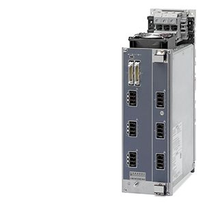
Power Output Module (POM)
- Заказные данные (4)
- Аксессуары (5)
- Информационные материалы
Дизайн
- Module (encapsulated) in a metal enclosure
- 9 outputs for connecting resistive loads
- There are four versions:
- POM4320 busbar mounting (IEC): a current of up to 16 A can be used per output.
- POM4320 busbar mounting (UL): a current of up to 15 A can be used per output.
- POM4320 IEC real panel mounting: a current of up to 16 A can be used per output.
- POM4320 UL rear panel mounting: a current of up to 15 A can be used per output.
- Connection of the phases via rear busbar adapter or connecting terminals
- Two-pole connection of heat emitters using mating connectors (mating connectors are included in the scope of supply!)
- Two fuses per output for supply and return line in a fuse module which can be plugged on and pulled off
- Heat dissipation by fan fitted to top of module
- Internal serial interface
- Three diagnostics LEDs for displaying module faults
- Nine diagnostics LEDs for displaying output errors
Функции
Protector elements
- Power triacs:
- Protection of triacs and opto-triacs against overvoltages by Transil diodes
- Transfer of the diagnostics information to the higher-level control system
Control modes
- Half-wave control:This is the control method used in normal operation. At every zero crossover, the channel is controlled depending on the parameterized setpoint value. The control variable is set to values between 0 and 100%. The reference basis is 1 second.
With half-wave control, it is possible to control loads with peak inrush currents of up to 15 A.
Output power
- 9 power output channels, 400V/480V each (3 outputs per phase)
- Switching capacity per output:
- POM4320 busbar mounting (IEC): max. 6400 W at 400 V or 7680 W at 480 V
- POM4320 busbar mounting (UL): max. 6 000 W at 400 V or 7 200 W at 480 V
- Switching capacity per POM:
- POM4320 busbar mounting (IEC): max. 57 600 W at 400 V or 69 120 W at 480 V
- POM4320 busbar mounting (UL): max. 54 000 W at 400 V or 64 800 W at 480 V
Ventilation
- A fan module can be optionally mounted at the top of the rack so that 4 POMs can be ventilated and controlled depending on the internal temperature.
Temperature monitoring
- There is an NTC thermistor in the device for monitoring the internal temperature. This temperature-dependent resistor switches off the power outputs of the module from an internal temperature of 100 °C ± 3 °C (not yet finalized).
Fuses
- IEC versions: Two 16 A fuses are available for each power output in a fuse module that can be accessed from the front to protect the power triacs.
Diagnostics options
Diagnostics functions are provided to detect the following faults as standard:
- Implicit diagnostics means that the heating power is not influenced by the diagnostics themselves
- Outgoing fuse is defective / triac at high resistance (exception: setpoint value 0%)
- Incoming line fuse is defective
- Triac has failed (exception: setpoint value 100%)
- Emitter cable is defective (short-circuit and interruption)
- Load defective (short-circuit and interruption)
- Monitoring of supply voltage
Line voltage compensation
- Internal compensation is carried out to compensate line voltage fluctuations
- The function runs on the HCS master; it can be switched on and off by the user
- The measured voltage values from each POM are available to the HCS master
Технические данные
Order number
6BK1943-2AA00-0AA0
6BK1943-2BA00-0AA0
6BK1943-2CA00-0AA0
6BK1943-2DA00-0AA0
HCS POM4320 BUSBAR MOUNTING (IEC)
HCS POM4320 BUSBAR MOUNTING (UL)
HCS POM4320 PANEL MOUNTING (IEC)
HCS POM4320 PANEL MOUNTING (UL)
General information
Product brand name
SIPLUS
Product designation
POM4320 BUSBAR MOUNTING (IEC)
POM4320 BUSBAR MOUNTING (UL)
POM4320 rear panel mounting (IEC)
POM4320 rear panel mounting (UL)
Type of control of heat emitters
Half-wave control and soft start
Installation type/mounting
Mounting type
Busbar mounting
Backplane mounting
Mounting position
vertical
Type of ventilation
Self-ventilation
Supply voltage
Type of supply voltage
AC
Rated value (AC)
400 V
Relative negative tolerance
10 %
Relative positive tolerance
30 %
Line frequency
● Rated value 1
50 Hz
● Rated value 2
60 Hz
● Relative symmetrical tolerance
5 %
Mains buffering
● Recovery time after power failure, typ.
1 s
Resistance thermometer (RTD)
● Design of electrical connection for supply voltage
Busbar adapter, 3-pole + PE
Terminal, 3-pin
— Connectable conductor cross-sections, solid
1x (1.5 ... 50 mm²)
— Connectable conductor cross-sections, finely stranded with wire end processing
1x (1.5 ... 35 mm²)
— Connectable conductor cross-sections for AWG cables
1x (16 ... 1)
Power supply for the electronics
Design of the power supply
Power supply via CIM
Power
Power consumption, max.
8 W
Power electronics
Type of load
Ohmic load
Power capacity, max.
69.1 kW
64.8 kW
69.1 kW
64.8 kW
● for delta connection with fan at 40 °C, max.
69.1 kW
64.8 kW
69.1 kW
64.8 kW
Switching capacity current per phase, max.
83 A
80 A
83 A
80 A
Short-time withstand current (SCCR) acc. to UL 508A
50 kA
50 kA
Heating power
● Number of digital outputs
9
● Number of heat emitters per output, max.
1
● Output voltage for heating power
400 V
● Power carrying capacity per output, min.
200 W
● Power carrying capacity per output, max.
7 680 W
7 200 W
7 680 W
7 200 W
— for heating elements with high inrush current, max.
4 000 W
3 000 W
4 000 W
3 000 W
● Output current for heating power
16 A
15 A
16 A
15 A
● Peak current
150 A
135 A
150 A
135 A
● Melting I2t value
250 A²·s
225 A²·s
250 A²·s
225 A²·s
● Design of short-circuit protection per output
Fuse 16 A
Fuse 15 A
Fuse 16 A
Fuse 15 A
● Design of overvoltage protection
Transil Diode
Integration and conversion time/resolution per channel
● Design of electrical connection at output for heating and fan
Connector, 3-pole with spring-loaded connection
— Connectable conductor cross-sections, solid
1x (0.2 ... 10 mm²)
— Connectable conductor cross-sections, finely stranded with wire end processing
1x (0.25 ... 6 mm²)
— Connectable conductor cross-sections for AWG cables, stranded
1x (24 ... 8)
Interfaces
Interfaces/bus type
system interface
Interrupts/diagnostics/status information
Number of status displays
12
LED status display
LED green = ready, LED yellow = heating on/off, LED red = error display, LED red = error for each channel
Diagnostics function
Voltage diagnostics
Diagnostic messages
● Wire-break
Yes
● Fuse blown
Yes
● Heat emitter defect
Yes
Integrated Functions
Monitoring functions
● Temperature monitoring
Yes
● Type of temperature monitoring
NTC thermistor
Measuring functions
● Voltage measurement
Yes
Potential separation
Design of electrical isolation
Optocoupler and/or protective impedance between main circuit and PELV
between the outputs
No
Isolation
Overvoltage category
III
EMC
EMC interference emission
Limit value in accordance with IEC 61000-6-4:2007 + A1:2011
Electrostatic discharge acc. to IEC 61000-4-2
4 kV contact discharge / 8 kV air discharge
Field-related interference acc. to IEC 61000-4-3
10 V/m (80 ... 1 000 MHz), 3 V/m (1.4 ... 2.0 GHz), 1 V/m (2.0 ... 2.7 GHz)
Conducted interference due to burst acc. to IEC 61000-4-4
2 kV power supply lines, 2 kV load lines
Conducted interference due to surge acc. to IEC 61000-4-5
on supply and load lines: 1 kV symmetric, 2 kV unsymmetric
Conducted interference due to high-frequency radiation acc. to IEC 61000-4-6
10 V (0.15 ... 80 MHz)
Degree and class of protection
IP degree of protection
IP20
Standards, approvals, certificates
Degree of pollution
2
Device tag according to DIN EN 81346-2
Q
Ambient conditions
Ambient temperature during operation
● min.
0 °C
● max.
55 °C
Ambient temperature during storage/transportation
● Storage, min.
-25 °C
● Storage, max.
70 °C
● Transportation, min.
-25 °C
● Transportation, max.
70 °C
Air pressure acc. to IEC 60068-2-13
● Operation, min.
860 hPa
● Operation, max.
1 080 hPa
● Storage, min.
660 hPa
● Storage, max.
1 080 hPa
● Installation altitude above sea level, max.
2 000 m
Relative humidity
● Operation at 25 ℃, max.
95 %
● Operation at 50 ℃, max.
50 %; 95 % at 25 °C, decreasing linearly to 50 % at 50 °C
Vibrations
● Vibration resistance during operation acc. to IEC 60068-2-6
10 ... 58 Hz / 0.075 mm, 58 ... 150 Hz / 1 g
● Vibration resistance during storage acc. to IEC 60068-2-6
5 ... 8.5 Hz / 3.5 mm, 8.5 ... 500 Hz / 1 g
Shock testing
● Shock resistance during operation acc. to IEC 60068-2-27
15 g / 11 ms / 3 shocks/axis
● Shock resistance during storage acc. to IEC 60068-2-29
25 g / 6 ms / 1 000 shocks/axis
Dimensions
Width
104 mm
Height
340 mm
344 mm
Depth
250 mm
217 mm