
- Каталог оборудования Siemens
- Каталог продуктов Siemens Industry
- Приводная техника
- Техника автоматизации
- Системы автоматизации
- Системы визуализации SIMATIC HMI
- Системы идентификации
- Промышленные коммуникации SIMATIC NET
- Промышленные аппараты управления SIRIUS
- Промышленные информационные технологии
- Управление на базе РС
- Системы управления процессом
- Контрольно-измерительные приборы
- Анализаторы процесса
- Блоки питания SITOP
- Продукты для специальных требований
- Energy
- Автоматизация и безопасность зданий
- Низковольтная коммутационная техника
- Технология безопасности
- Системные решения и продукты для отраслей
- Сервис
Power output modules
- Заказные данные (2)
- Информационные материалы
Информационные материалы
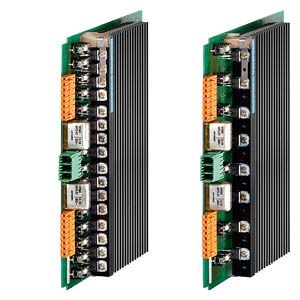
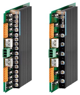
The power output modules are an important component of the SIPLUS HCS716I heater control.
Three different power output modules can be used depending on the application:
- LA716I power output module – the innovative version
- LA716I HP power output module – the HighPower version
LA716I power output module
The innovative power output module provides 16 channels for connecting resistive loads. Up to 1 150 W can be used per output channel.
LA716I HP power output module
The HighPowerversion provides 8 channels for connecting resistive loads. Up to 2,300 W can be used per output channel.
Дизайн
- Connection of the heat emitters by means of two 8-pin mating connectors (the heat emitter and mating connector must be ordered separately.)
- Mains infeed at the front:
- LA716I and LA716I HP power output modules: 3-pole connector (Lx/N/Ly)
Функции
Power switching elements
- Power triacs with zero crossover switching
- Protection of triacs and opto-triacs against overvoltages by Transil diodes
Output power
LA716I power output module
- 16 power channels of 230 V each (8 outputs per phase)
- Max. 14 720 W switching capacity per module
LA716I HP power output module
- 8 power channels of 230 V each (4 outputs per phase)
- Max. 14 720 W switching capacity per module
Temperature monitoring
There is an NTC thermistor on the heat sink for monitoring its temperature. In the event of an overtemperature, this temperature-dependent resistor issues a signal to the higher-level controller.
Fuses
LA716I power output module
- Each output is protected by a 5 A fuse in an accessible fuse holder for protection of the power triac.
- A plexiglass cover is provided as a shock hazard protection on the front.
LA716I HP power output module
- Each output is protected by a 10 A fuse in an accessible fuse holder for protection of the power triac.
- A plexiglass cover is provided as a shock hazard protection on the front.
Diagnostics facilities
Diagnostics functions are provided as standard to detect the following faults:
- Circuit breaker triac at high resistance or internal fuse blown
- Channel fuse blown on the module
- External fault such as blown fuse, heat emitter or cable breakage
Технические данные
Order number
6BK1700-4BA80-0AA0
6BK1700-4CA00-0AA0
HCS Power output module LA716I
HCS Power output module LA716I HP
General information
Product designation
HCS716I power module LA716I
HCS716I power module LA716I HP
Type of control of heat emitters
Full-wave control
Full-wave control
Installation type/mounting
Mounting type
Mounting clip in the rack
Mounting clip in the rack
Mounting position
vertical
vertical
Type of ventilation
Self ventilation or forced ventilation
Self ventilation or forced ventilation
Supply voltage
Rated value (AC)
230 V
230 V
Relative negative tolerance
18 %
18 %
Relative positive tolerance
15 %
15 %
Line frequency
● Rated value 1
50 Hz
50 Hz
● Rated value 2
60 Hz
60 Hz
● Relative symmetrical tolerance
5 %
5 %
Resistance thermometer (RTD)
● Design of electrical connection for supply voltage
Connector, 3-pin
Connector, 3-pin
— Connectable conductor cross-sections, solid
1x (0.2 ... 10 mm²)
1x (0.2 ... 10 mm²)
— Connectable conductor cross-sections, finely stranded with wire end processing
1x (0.25 ... 6 mm²)
1x (0.25 ... 6 mm²)
— Connectable conductor cross-sections for AWG cables
24 ... 8
24 ... 8
Power supply for the electronics
Design of the power supply
Power supply via module rack
Power supply via module rack
Power electronics
Type of load
Ohmic load
Ohmic load
Power capacity, max.
14.72 kW
14.72 kW
● for delta connection with fan at 40 °C, max.
14.72 kW
14.72 kW
● for delta connection without fan at 40 °C, max.
6.5 kW
6.5 kW
Switching capacity current per phase, max.
32 A
32 A
Heating power
● Number of digital outputs
16
8
● Number of heat emitters per output, max.
1
1
● Output voltage for star connection
230 V
230 V
● Power carrying capacity per output, min.
75 W
75 W
● Power carrying capacity per output, max.
1 150 W
2 300 W
● Output current for heating power
5 A
10 A
● Design of short-circuit protection per output
Fuse 5 A
Fuse 10 A
● Design of overvoltage protection
Transil diodes
Transil diodes
Integration and conversion time/resolution per channel
● Design of electrical connection at output for heating and fan
Socket strip, 8-pole
Socket strip, 8-pole
— Connectable conductor cross-sections, solid
1x (0.2 ... 1.5 mm²)
1x (0.2 ... 1.5 mm²)
— Connectable conductor cross-sections, finely stranded with wire end processing
1x (0.2 ... 1.5 mm²)
1x (0.2 ... 1.5 mm²)
— Connectable conductor cross-sections for AWG cables, stranded
28 ... 16
28 ... 16
Interfaces
Interfaces/bus type
system interface
system interface
Interrupts/diagnostics/status information
Diagnostic messages
● Wire-break
Yes
Yes
● Fuse blown
Yes
Yes
● Heat emitter defect
Yes
Yes
Integrated Functions
Monitoring functions
● Type of temperature monitoring
NTC thermistor
NTC thermistor
Potential separation
Design of electrical isolation
Optocoupler between main circuit and SELV / PELV
Optocoupler between main circuit and SELV / PELV
between the outputs
No
No
Isolation
Overvoltage category
III
III
EMC
EMC interference emission
in accordance with EN 61000-6-4:2007 + A1:2011
in accordance with EN 61000-6-4:2007 + A1:2011
Electrostatic discharge acc. to IEC 61000-4-2
4 kV contact discharge / 8 kV air discharge
4 kV contact discharge / 8 kV air discharge
Field-related interference acc. to IEC 61000-4-3
10 V/m (80 ... 1 000 MHz), 3 V/m (1.4 ... 2.0 GHz), 1 V/m (2.0 ... 2.7 GHz)
10 V/m (80 ... 1 000 MHz), 3 V/m (1.4 ... 2.0 GHz), 1 V/m (2.0 ... 2.7 GHz)
Conducted interference due to burst acc. to IEC 61000-4-4
2 kV voltage supply cables / 2 kV signal cables
2 kV voltage supply cables / 2 kV signal cables
Conducted interference due to surge acc. to IEC 61000-4-5
on power supply and signal cables: 1 kV symmetrical, 2 kV unsymmetrical
on power supply and signal cables: 1 kV symmetrical, 2 kV unsymmetrical
Conducted interference due to high-frequency radiation acc. to IEC 61000-4-6
10 V (0.15 ... 80 MHz)
10 V (0.15 ... 80 MHz)
Degree and class of protection
IP degree of protection
IP00
IP00
Standards, approvals, certificates
Certificate of suitability
CE, KCC
CE, KCC
Degree of pollution
2
2
Device tag according to DIN EN 81346-2
Q
Q
Ambient conditions
Ambient temperature during operation
● min.
0 °C
0 °C
● max.
55 °C
55 °C
Ambient temperature during storage/transportation
● Storage, min.
-40 °C
-40 °C
● Storage, max.
70 °C
70 °C
● Transportation, min.
-40 °C
-40 °C
● Transportation, max.
70 °C
70 °C
Air pressure acc. to IEC 60068-2-13
● Operation, min.
860 hPa
860 hPa
● Operation, max.
1 080 hPa
1 080 hPa
● Storage, min.
660 hPa
660 hPa
● Storage, max.
1 080 hPa
1 080 hPa
● Installation altitude above sea level, max.
2 000 m
2 000 m
Relative humidity
● at 25 °C, max.
95 %
95 %
Vibrations
● Vibration resistance during operation acc. to IEC 60068-2-6
10 ... 58 Hz / 0.15 mm, 58 ... 150 Hz / 1 g
10 ... 58 Hz / 0.15 mm, 58 ... 150 Hz / 1 g
● Vibration resistance during storage acc. to IEC 60068-2-6
5 ... 9 Hz / 3.5 mm, 9 ... 500 Hz / 1 g
5 ... 9 Hz / 3.5 mm, 9 ... 500 Hz / 1 g
Shock testing
● Shock resistance acc. to IEC 60068-2-27
15 g / 11 ms / 3 shocks/axis
15 g / 11 ms / 3 shocks/axis
● Shock resistance acc. to IEC 60068-2-29
25 g / 6 ms / 1 000 shocks/axis
25 g / 6 ms / 1 000 shocks/axis
Dimensions
Width
31 mm
31 mm
Height
233.4 mm
233.4 mm
Depth
279 mm
279 mm
Дополнительно
Design
for power output module
Type
Data link
- 5 A quick blow/250 V
LA716, LA716I
200021116
- 10 A quick blow/250 V
LA716I HP
A5E00186303
Mating connectors
- 3-pin for mains connection
LA716I, LA716I HP
A5E30280233
- 8-pin for connection of the heat emitters
LA716, LA716I, LA716I HP
A5E00507233
Дальнейшая информация
For more information, visit http://www.siemens.com/siplus-hcs.