
- Каталог оборудования Siemens
- Каталог продуктов Siemens Industry
- Приводная техника
- Техника автоматизации
- Системы автоматизации
- Промышленные системы автоматизации SIMATIC
- Программируемые контроллеры
- Логические модули LOGO!
- Базовый контроллер
- SIMATIC S7
- S7-1500
- S7-300/ S7-300F/ SIPLUS S7-300
- S7-400/S7-400H/S7-400F/FH
- Demonstration models
- Central processing units
- Signal modules
- Function modules
- Communication
- Connection method
- Racks
- SIPLUS S7-400 racks
- Interface modules
- PS 405/407 power supply
- SIPLUS S7-400 power supplies
- Accessories
- S7-400H
- S7-400F/FH
- Контроллеры для распределенных систем
- Программный контроллер
- Дополнительные компоненты
- Распределенный ввод/вывод
- Система автоматизации SIMATIC TDC
- Программное обеспечение для SIMATIC S7/WinAC
- Программаторы
- SIEMENS Solution Partner
- Test
- Программируемые контроллеры
- Motion Control - система SIMOTION
- Системы автоматизации на базе СЧПУ SINUMERIK
- Система соединителей/ шкафы управления
- Программное обеспечение для систем автоматизации
- Промышленные системы автоматизации SIMATIC
- Системы визуализации SIMATIC HMI
- Системы идентификации
- Промышленные коммуникации SIMATIC NET
- Промышленные аппараты управления SIRIUS
- Промышленные информационные технологии
- Управление на базе РС
- Системы управления процессом
- Контрольно-измерительные приборы
- Анализаторы процесса
- Блоки питания SITOP
- Продукты для специальных требований
- Системы автоматизации
- Energy
- Автоматизация и безопасность зданий
- Низковольтная коммутационная техника
- Технология безопасности
- Системные решения и продукты для отраслей
- Сервис

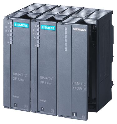
SIPLUS Y-Link for S7-400H
- Заказные данные (4)
- Аксессуары (2)
- Информационные материалы
Информационные материалы
- Bus coupler for transition from a redundant PROFIBUS DP master system to a single-channel PROFIBUS DP master system
- For connection of devices with only one PROFIBUS DP interface to the redundant PROFIBUS DP master system of the SIMATIC S7-400H
Note:
SIPLUS extreme products are based on SIMATIC standard products. The contents listed here were taken from the respective standard products. SIPLUS extreme specific information was added.
Technical documentation on SIPLUS can be found here:
http://www.siemens.de/siplus-extremeОбласть применения
The Y-Link is a transceiver for the transition from a redundant PROFIBUS master system to a single-channel PROFIBUS DP master system. It is used to connect devices with a single PROFIBUS DP interface as switched I/O to S7-400H.
Дизайн
The Y-link comprises:
- 2 IM 153-2 High Feature Outdoor interface modules
- 1 Y coupler
- 1 BM IM/IM bus module
- 1 BM Y-coupler bus module
Snapped on mounting rails for setup with active bus modules.
Configuration options and limitations
A redundant PROFIBUS DP master system can be extended by means of Y links in the following way:
- The number of Y links on a redundant DP master system is only limited by the maximum number of stations. The maximum number of connectable slaves depends on the length of the user data and configuration message frames. The total length of each may not exceed 244 bytes (see slave technical data). Generally, the following applies:
- Max. 64 stations in the lower-level DP master system
- Max. 236 slots in the lower-level DP master system
- Y link configuration and user data message frames comprise message frame contents of the lower-level slaves. The maximum frame length is therefore 244 bytes.
- Direct communication and equidistance not possible in the lower-level master system
Функции
Y link
- Transmission rates for the redundant master system:
9.6 Kbit/s to 12 Mbit/s - Bumpless switchover of the redundant PROFIBUS DP master system's active channel.
- Supports system changes on a SIMATIC S7-400H during operation
- Diagnostics via LEDs and the user program
Y coupler
- Transmission rates for the lower-level master system (independent of redundant DP master system):
187.5 Kbit/s to 12 Mbit/s - Electrical isolation between lower-level DP master system and power supply via the coupler
- IP20 degree of protection
Principle of operation
The Y link maps the lower-level DP master system on the redundant PROFIBUS DP master system as a switched PROFIBUS DP slave .
The Y coupler and the lower-level DP master system form an independent bus system and operate decoupled from the redundant bus system.
The Y link as a DP slave on the redundant DP master system acts as a proxy for the stations on the lower-level DP master system with regard to data.
Configuration
The Y link can be configured with STEP 7 as of Version 5.4. It is not necessary to configure the Y coupler.
When STEP 7 calculates the bus parameters, the stations connected on the lower-level DP master system as well as the Y link itself are taken into account.
Parameter assignment of the DP slaves
The redundant DP master system assigns the parameters for the DP slaves in the lower-level DP master system via the Y link.
Технические данные
Order number
6AG1153-2BA10-7XB0
SIPLUS ET200M IM153-2 HF
General information
Vendor identification (VendorID)
801Eh
Supply voltage
Rated value (DC)
● 24 V DC
Yes
permissible range (ripple included), lower limit (DC)
20.4 V
permissible range (ripple included), upper limit (DC)
28.8 V
external protection for power supply lines (recommendation)
2,5 A
Mains buffering
● Mains/voltage failure stored energy time
5 ms
Input current
Current consumption, max.
650 mA; with 24 V DC supply
Inrush current, typ.
3 A
I²t
0.1 A²·s
Output current
for backplane bus (5 V DC), max.
1.5 A
Power loss
Power loss, typ.
5.5 W
Address area
Addressing volume
● Inputs
244 byte
● Outputs
244 byte
Hardware configuration
Number of modules per DP slave interface, max.
12
Time stamping
Accuracy
1 ms; 1ms at up to 8 modules; 10ms at up to 12 modules
Number of message buffers
15
Messages per message buffer
20
Number of stampable digital inputs, max.
128; Max. 128 signals/station; max. 32 signals/slot
Time format
RFC 1119
Time resolution
0.466 ns
Time interval for transmitting the message buffer if a message is present
1 000 ms
Time stamp on signal change
rising / falling edge as signal entering or exiting
Interfaces
Interface physics, RS 485
Yes
Interface physics, FOC
No
PROFIBUS DP
● Node addresses
1 to 125 permitted
● automatic detection of transmission rate
Yes
● Output current, max.
70 mA
● Transmission rate, max.
12 Mbit/s
● Transmission procedure
RS 485
● SYNC capability
Yes
● FREEZE capability
Yes
● Direct data exchange (slave-to-slave communication)
Yes; as publisher with all IO, as subscriber with F-IO only
● Connector type
9-pin sub D
1. Interface
DP slave
● GSD file
SI05801E.GSG
● automatic baud rate search
Yes
Protocols
Bus protocol/transmission protocol
PROFIBUS DP to EN 50170
Isolation
Isolation tested with
Isolation voltage 500 V
Degree and class of protection
Degree of protection acc. to EN 60529
● IP20
Yes
Standards, approvals, certificates
CE mark
Yes
Ambient conditions
Ambient temperature during operation
● min.
-40 °C; = Tmin; Startup @ -25 °C
● max.
70 °C; = Tmax
Ambient temperature during storage/transportation
● min.
-40 °C
● max.
70 °C
Extended ambient conditions
● relative to ambient temperature-atmospheric pressure-installation altitude
Tmin ... Tmax at 1080 hPa ... 795 hPa (-1000 m ... +2000 m) // Tmin ... (Tmax - 10K) at 795 hPa ... 658 hPa (+2000 m ... +3500 m) // Tmin ... (Tmax - 20K) at 658 hPa ... 540 hPa (+3500 m ... +5000 m)
● At cold restart, min.
-25 °C
Relative humidity
— With condensation, tested in accordance with IEC 60068-2-38, max.
100 %; RH incl. condensation/frost (no commissioning under condensation conditions)
Resistance
— against biologically active substances / conformity with EN 60721-3-3
Yes; Class 3B2 mold, fungus and dry rot spores (with the exception of fauna). The supplied connector covers must remain on the unused interfaces during operation!
— against chemically active substances / conformity with EN 60721-3-3
Yes; Class 3C4 (RH < 75%) incl. salt spray according to EN 60068-2-52 (degree of severity 3). The supplied connector covers must remain on the unused interfaces during operation!
— against mechanically active substances / conformity with EN 60721-3-3
Yes; Class 3S4 incl. sand, dust. The supplied connector covers must remain on the unused interfaces during operation!
Configuration
Configuration software
● STEP 7
Yes; STEP 7 / COM PROFIBUS / non-Siemens tools via GSD file
Dimensions
Width
40 mm
Height
125 mm
Depth
117 mm
Weights
Weight, approx.
360 g
Order number
6AG1197-1LB00-4XA0
SIPLUS S7 Y-Koppler
General information
Requirements for DP master system
● Length of parameter assignment telegram
244 byte
Supply voltage
Design of the power supply
via bus module
permissible range, lower limit (DC)
20.4 V
permissible range, upper limit (DC)
28.8 V
Interfaces
PROFIBUS DP
Properties of the lower-level DP master system
— Transmission rate, max.
12 Mbit/s; 45.45 kbit/s to 12 Mbit/s
— Termination of lower-level DP master system
Active terminating resistor (Bus Terminator)
— Use of OLM/OBT
Yes
— Use of RS 485 repeaters, max.
9
— Number of DP slaves, max.
31; 64 when using RS 485 repeaters or OLM/OBT
Protocols
PROFIBUS DP
Yes
Interrupts/diagnostics/status information
Status indicator
No
Alarms
No
Diagnostic functions
Yes
Potential separation
to lower-level DP master system
Yes
Ambient conditions
Ambient temperature during operation
● min.
0 °C; = Tmin
● max.
60 °C; = Tmax
Ambient temperature during storage/transportation
● min.
-40 °C
● max.
70 °C
Extended ambient conditions
● relative to ambient temperature-atmospheric pressure-installation altitude
Tmin ... Tmax at 1080 hPa ... 795 hPa (-1000 m ... +2000 m) // Tmin ... (Tmax - 10K) at 795 hPa ... 658 hPa (+2000 m ... +3500 m) // Tmin ... (Tmax - 20K) at 658 hPa ... 540 hPa (+3500 m ... +5000 m)
Relative humidity
— With condensation, tested in accordance with IEC 60068-2-38, max.
100 %; RH incl. condensation/frost (no commissioning under condensation conditions)
Resistance
— against biologically active substances / conformity with EN 60721-3-3
Yes; Class 3B2 mold, fungus and dry rot spores (with the exception of fauna). The supplied connector covers must remain on the unused interfaces during operation!
— against chemically active substances / conformity with EN 60721-3-3
Yes; Class 3C4 (RH < 75%) incl. salt spray according to EN 60068-2-52 (degree of severity 3). The supplied connector covers must remain on the unused interfaces during operation!
— against mechanically active substances / conformity with EN 60721-3-3
Yes; Class 3S4 incl. sand, dust. The supplied connector covers must remain on the unused interfaces during operation!
Dimensions
Width
40 mm
Height
125 mm
Depth
130 mm
Weights
Weight, approx.
200 g
Order number
6AG1195-7HD10-2XA0
SIPLUS_ET200M_DP_Busmodul
Standards, approvals, certificates
CE mark
Yes
UL approval
Yes; File E239877
FM approval
Yes; CofC 3028431
RCM (formerly C-TICK)
Yes
KC approval
Yes
EAC (formerly Gost-R)
Yes
Ambient conditions
Ambient temperature during operation
● min.
-40 °C; = Tmin
● max.
70 °C; = Tmax; 60 °C @ UL/cUL, ATEX and FM use
Ambient temperature during storage/transportation
● min.
-40 °C
● max.
70 °C
Extended ambient conditions
● relative to ambient temperature-atmospheric pressure-installation altitude
Tmin ... Tmax at 1080 hPa ... 795 hPa (-1000 m ... +2000 m) // Tmin ... (Tmax - 10K) at 795 hPa ... 658 hPa (+2000 m ... +3500 m) // Tmin ... (Tmax - 20K) at 658 hPa ... 540 hPa (+3500 m ... +5000 m)
Relative humidity
— With condensation, tested in accordance with IEC 60068-2-38, max.
100 %; RH incl. condensation/frost (no commissioning under condensation conditions)
Resistance
— against biologically active substances / conformity with EN 60721-3-3
Yes; Class 3B2 mold, fungus and dry rot spores (with the exception of fauna). The supplied connector covers must remain on the unused interfaces during operation!
— against chemically active substances / conformity with EN 60721-3-3
Yes; Class 3C4 (RH < 75%) incl. salt spray according to EN 60068-2-52 (degree of severity 3). The supplied connector covers must remain on the unused interfaces during operation!
— against mechanically active substances / conformity with EN 60721-3-3
Yes; Class 3S4 incl. sand, dust. The supplied connector covers must remain on the unused interfaces during operation!
Accessories
belongs to product
ET 200M
Dimensions
Width
97 mm
Height
92 mm
Depth
30 mm
Weights
Weight, approx.
133 g