
- Каталог оборудования Siemens
- Каталог продуктов Siemens Industry
- Приводная техника
- Техника автоматизации
- Системы автоматизации
- Промышленные системы автоматизации SIMATIC
- Программируемые контроллеры
- Распределенный ввод/вывод
- Система автоматизации SIMATIC TDC
- Программное обеспечение для SIMATIC S7/WinAC
- Программаторы
- SIEMENS Solution Partner
- Test
- Motion Control - система SIMOTION
- Системы автоматизации на базе СЧПУ SINUMERIK
- Система соединителей/ шкафы управления
- Программное обеспечение для систем автоматизации
- Промышленные системы автоматизации SIMATIC
- Системы визуализации SIMATIC HMI
- Системы идентификации
- Промышленные коммуникации SIMATIC NET
- Промышленные аппараты управления SIRIUS
- Промышленные информационные технологии
- Управление на базе РС
- Системы управления процессом
- Контрольно-измерительные приборы
- Анализаторы процесса
- Блоки питания SITOP
- Продукты для специальных требований
- Системы автоматизации
- Energy
- Автоматизация и безопасность зданий
- Низковольтная коммутационная техника
- Технология безопасности
- Системные решения и продукты для отраслей
- Сервис
SIPLUS S7-400 power supplies
- Заказные данные (4)
- Аксессуары (3)
- Информационные материалы
Информационные материалы
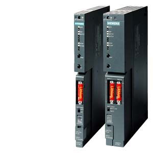
- Power supplies for SIPLUS S7-400
- For conversion of AC or DC line voltages to the 5 V DC and 24 V DC operating voltages required
- 4 A, 10 A and 20 A output currents
Note:
SIPLUS extreme products are based on SIMATIC standard products. The contents listed here were taken from the respective standard products. SIPLUS extreme specific information was added.
Technical documentation on SIPLUS can be found here:
http://www.siemens.de/siplus-extremeОбласть применения
The power supplies supply the S7-400 modules with their 5 V DC and 24 V DC operating voltages via the backplane bus.
Power supplies are available for AC line voltages of 85 to 264 V and for DC voltages of 19.2 to 300 V.
One power supply module is required per rack.
Exception:
With interfaces with current transfer, the power supply module in the central controller also supplies all modules in the expansion units.The load voltage for supplying sensors and actuators must be made available separately.
There are also power supplies to make both the standard system and the H system fail-safe (redundant power supplies).
Дизайн
The power supply modules are inserted at the far left in the rack (starting from slot 1). Depending on the version, they occupy slots 1 to 3. The modules are enclosed and are cooled via natural convection.
The front of the module contains:
- LED displays:
LEDS indicate internal faults, correct output voltages 5 V DC, 24 V DC, and correct back-up battery voltage. - Pushbutton for fault acknowledgment.
- On/off switch for output voltages.
- Battery compartment for back-up battery (batteries).
- Switch for battery monitoring.
- Supply voltage selector switch (not for wide-range power supplies).
- Power supply connection.
The back-up battery is optional and must be ordered in addition. For power supplies at and above 10 A, two back-up batteries are recommended.
Технические данные
Order number
6AG1405-0KA02-7AA0
6AG1405-0KR02-7AA0
6AG1407-0KA02-7AA0
6AG1407-0KR02-7AA0
SIPLUS S7-400 PS405 10A
SIPLUS S7-400 PS405 10A
SIPLUS S7-400 PS407 10A
SIPLUS S7-400 PS407 10A
General information
Product type designation
PS405, 24/48/60 VDC, 5 VDC/10 A
PS405,24/48/60 VDC,5 VDC/10 A,RED
PS407,UC 120/230 V,5 VDC/10 A,RED.
Supply voltage
Rated value (DC)
● 24 V DC
Yes
Yes
● 48 V DC
Yes
Yes
● 60 V DC
Yes
Yes
● 120 V DC
Yes
Yes
● 230 V DC
Yes
Yes
permissible range, lower limit (DC)
19.2 V; Dynamic 18.5 V
19.2 V; Dynamic 18.5 V
88 V
88 V
permissible range, upper limit (DC)
72 V; dynamic 75.5 V
72 V; dynamic 75.5 V
300 V
300 V
Rated value (AC)
● 120 V AC
Yes
Yes
● 230 V AC
Yes
Yes
permissible range, lower limit (AC)
85 V
85 V
permissible range, upper limit (AC)
264 V
264 V
Line frequency
● Rated value 50 Hz
Yes
Yes
● Rated value 60 Hz
Yes
Yes
● permissible range, lower limit
47 Hz
47 Hz
● permissible range, upper limit
63 Hz
63 Hz
Mains buffering
● Mains/voltage failure stored energy time
20 ms
20 ms
20 ms
20 ms
● Mains buffering according to NAMUR recommendation
Yes
Yes
Yes
Yes
Input current
Rated value at 24 V DC
4 A
4 A
Rated value at 48 V DC
2 A
2 A
Rated value at 60 V DC
1.6 A
1.6 A
Rated value at 110 V DC
1 A; at 120 V DC
1 A; at 120 V DC
Rated value at 230 V DC
0.5 A
0.5 A
Rated value at 120 V AC
0.9 A
0.9 A
Rated value at 230 V AC
0.5 A
0.5 A
Inrush current, max.
18 A; Full width at half maximum 20 ms
18 A; Full width at half maximum 20 ms
63 A; Full width at half maximum 1 ms
63 A; Full width at half maximum 1 ms
Output voltage
Type of output voltage
DC
DC
DC
Rated value (DC)
● 5 V DC
Yes
Yes
Yes
Yes
● 24 V DC
Yes
Yes
Yes
Yes
Output current
for backplane bus (5 V DC), max.
10 A; 7A @ > 60 °C, no base load necessary
10 A; no base load required
10 A; no base load required
10 A; no base load required
for backplane bus (24 V DC), max.
1 A; idling-proof
1 A; idling-proof
1 A; idling-proof
1 A; idling-proof
Short-circuit protection
Yes
Yes
Yes
Yes
Power
Active power input, typ.
95 W
95 W
95 W
95 W
Power loss
Power loss, typ.
20 W
20 W
20 W
20 W
Battery
Backup battery
● Backup battery (optional)
Yes; 2x lithium AA; 3.6 V / 2.3 Ah
Yes; 0 °C to +60 °C: 2 x lithium AA; 3.6 V/2.3 Ah // -25 °C to +70 °C and/or 100% RH: 2 x external battery box 6AG1971-0AA00-7AA0 and 2 x MONO cell design D
Yes; 0 °C to +60 °C: 2 x lithium AA; 3.6 V/2.3 Ah // -25 °C to +70 °C and/or 100% RH: 2 x external battery box 6AG1971-0AA00-7AA0 and 2 x MONO cell design D
Yes; 0 °C to +60 °C: 2 x lithium AA; 3.6 V/2.3 Ah // -25 °C to +70 °C and/or 100% RH: 2 x external battery box 6AG1971-0AA00-7AA0 and 2 x MONO cell design D
Hardware configuration
Slots
● required slots
2
2
2
2
Potential separation
primary/secondary
Yes
Yes
Yes
Yes
EMC
Compliance with line harmonic distortion limits
● Compliance with line harmonic distortion acc. to IEC 61000-3-2, IEC 61000-3-3
Yes
Yes
Degree and class of protection
Protection class
1; with protective conductor
1; with protective conductor
1; with protective conductor
1; with protective conductor
Ambient conditions
Ambient temperature during operation
● min.
-25 °C; = Tmin
-25 °C; = Tmin; using the external battery box SIPLUS 6AG1971-0AA00-7AA0 for buffer mode
-25 °C; using the external battery box SIPLUS 6AG1971-0AA00-7AA0 for buffer mode
-25 °C; using the external battery box SIPLUS 6AG1971-0AA00-7AA0 for buffer mode
● max.
70 °C; = Tmax
70 °C; = Tmax; using the external battery box SIPLUS 6AG1971-0AA00-7AA0 for buffer mode
70 °C; using the external battery box SIPLUS 6AG1971-0AA00-7AA0 for buffer mode
70 °C; using the external battery box SIPLUS 6AG1971-0AA00-7AA0 for buffer mode
Extended ambient conditions
● relative to ambient temperature-atmospheric pressure-installation altitude
Tmin ... Tmax at 1080 hPa ... 795 hPa (-1000 m ... +2000 m) // Tmin ... (Tmax - 10K) at 795 hPa ... 658 hPa (+2000 m ... +3500 m) // Tmin ... (Tmax - 20K) at 658 hPa ... 540 hPa (+3500 m ... +5000 m)
Tmin ... Tmax at 1080 hPa ... 795 hPa (-1000 m ... +2000 m) // Tmin ... (Tmax - 10K) at 795 hPa ... 658 hPa (+2000 m ... +3500 m) // Tmin ... (Tmax - 20K) at 658 hPa ... 540 hPa (+3500 m ... +5000 m)
Tmin ... Tmax at 1080 hPa ... 795 hPa (-1000 m ... +2000 m) // Tmin ... (Tmax - 10K) at 795 hPa ... 658 hPa (+2000 m ... +3500 m) // Tmin ... (Tmax - 20K) at 658 hPa ... 540 hPa (+3500 m ... +5000 m)
Tmin ... Tmax at 1080 hPa ... 795 hPa (-1000 m ... +2000 m)
Relative humidity
— With condensation, tested in accordance with IEC 60068-2-38, max.
100 %; Relative humidity, incl. condensation / frost permitted (no commissioning under condensation conditions)
100 %; RH incl. condensation/frost (no commissioning if there is condensation). In buffer mode, use battery box SIPLUS 6AG1971-0AA00-7AA0 for high humidity
100 %; RH incl. condensation/frost (no commissioning if there is condensation). In buffer mode, use battery box SIPLUS 6AG1971-0AA00-7AA0 for high humidity
100 %; RH incl. condensation/frost (no commissioning if there is condensation). In buffer mode, use battery box SIPLUS 6AG1971-0AA00-7AA0 for high humidity
Resistance
— against biologically active substances / conformity with EN 60721-3-3
Yes; Class 3B2 mold, fungus and dry rot spores (with the exception of fauna). The supplied connector covers must remain on the unused interfaces during operation in corrosive atmospheres!
Yes; Class 3B2 mold, fungus and dry rot spores (with the exception of fauna). The supplied connector covers must remain on the unused interfaces during operation!
Yes; Class 3B2 mold, fungus and dry rot spores (with the exception of fauna). The supplied connector covers must remain on the unused interfaces during operation!
Yes; Class 3B2 mold, fungus and dry rot spores (with the exception of fauna). The supplied connector covers must remain on the unused interfaces during operation!
— against chemically active substances / conformity with EN 60721-3-3
Yes; Class 3C4 incl. salt spray according to EN 60068-2-52 (degree of severity 3). The supplied connector covers must remain on the unused interfaces during operation!
Yes; Class 3C4 (RH < 75%) incl. salt spray according to EN 60068-2-52 (degree of severity 3). The supplied connector covers must remain on the unused interfaces during operation!
Yes; Class 3C4 (RH < 75%) incl. salt spray according to EN 60068-2-52 (degree of severity 3). The supplied connector covers must remain on the unused interfaces during operation!
Yes; Class 3C4 (RH < 75%) incl. salt spray according to EN 60068-2-52 (degree of severity 3). The supplied connector covers must remain on the unused interfaces during operation!
— against mechanically active substances / conformity with EN 60721-3-3
Yes; Class 3S4 incl. sand, dust. The supplied connector covers must remain on the unused interfaces during operation!
Yes; Class 3S4 incl. sand, dust. The supplied connector covers must remain on the unused interfaces during operation!
Yes; Class 3S4 incl. sand, dust. The supplied connector covers must remain on the unused interfaces during operation!
Yes; Class 3S4 incl. sand, dust. The supplied connector covers must remain on the unused interfaces during operation!
Connection method
Connecting cables/cross-sections
3x 1.5 mm², solid or stranded wire with end sleeve, external diameter 3 mm to 9 mm
3x 1.5 mm², solid or stranded wire with end sleeve, external diameter 3 mm to 9 mm
3x 1.5 mm², solid or stranded wire with end sleeve, external diameter 3 mm to 9 mm
3x 1.5 mm², solid or stranded wire with end sleeve, external diameter 3 mm to 9 mm
Dimensions
Width
50 mm
50 mm
50 mm
50 mm
Height
290 mm
290 mm
290 mm
290 mm
Depth
217 mm
217 mm
217 mm
217 mm
Weights
Weight, approx.
1.2 kg
1 200 g
1 200 g
1 200 g
Дальнейшая информация
Brochures
Information material for downloading can be found in the Internet:
http://www.siemens.com/simatic/printmaterial