
- Каталог оборудования Siemens
- Каталог продуктов Siemens Industry
- Приводная техника
- Техника автоматизации
- Системы автоматизации
- Системы визуализации SIMATIC HMI
- Системы идентификации
- Промышленные коммуникации SIMATIC NET
- Промышленные аппараты управления SIRIUS
- Промышленные информационные технологии
- Управление на базе РС
- Системы управления процессом
- Контрольно-измерительные приборы
- Анализаторы процесса
- Блоки питания SITOP
- Продукты для специальных требований
- Energy
- Автоматизация и безопасность зданий
- Низковольтная коммутационная техника
- Технология безопасности
- Системные решения и продукты для отраслей
- Сервис
SIDOOR AT40 elevator door drive
- Заказные данные (2)
- Информационные материалы
Информационные материалы

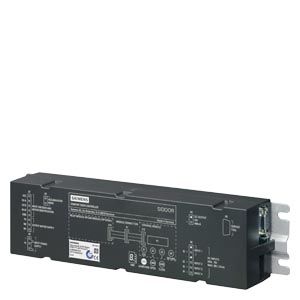
SIDOOR AT40 elevator door drive (relay module version)
SIDOOR AT40 – SIDOOR enables the quick, easy and versatile installation, configuration and operation of a wide range of elevator door systems.
- Version:
- Relay module
- CAN module
- For dynamic door weights up to 600 kg
- Automatic door weight detection
- 4 to 8 kg maximum counterweight (depending on motor version)
- Operating temperature -20 to +50 °C
- Flexible motor management (four different motor types), automatic detection
- Opening width 0.3 to 5 m
- Auxiliary power output 24 V DC ± 15 %; 0.4 A (short-circuit-proof)
- Output stage short-circuit-proof
- Supports power-optimized operation in the elevator cabin
- Vandal-proof
- IP54 degree of protection for 180 to 600 kg motor versions, gear unit IP40 (SIDOOR M5: entirely IP54)
- The current operating states are indicated via a 7-segment display directly in the elevator door drive or externally using the Software Kit or Service Tool, see "Accessories".
Область применения
The comfort SIDOOR AT40 elevator door drive is an intelligent door control system which enables the opening and closing of cabin and shaft doors at adjustable speeds and accelerations.
The maintenance-free, variable speed drive unit comprises a DC motor with non-self-locking gearing.
Four different motors are available:
- SIDOOR M2 geared motor (24 V DC/1.8 A; motor for max. total door leaf weight of 120 kg)
- SIDOOR M3 geared motor (30 V DC/4.0 A; motor for max. total door leaf weight of 180 kg)
- SIDOOR M4 geared motor (30 V DC/4.0 A; motor for max. total door leaf weight of 400 kg)
- SIDOOR M5 geared motor (30 V DC/7.5 A; motor for max. overall door leaf weight of 600 kg)
They must be ordered separately, see "Geared motors".
Operation of the door drive does not require a limit switch. The door width and the "OPEN"/"CLOSE" positions are determined automatically.
The current operating states are indicated by a 7‑Segment display directly in the SIDOOR AT40 elevator door drive. They can also be displayed externally with the aid of the Software Kit or Service Tool, see "Additional Units".
Power transmission is via a toothed belt, which passes over a deflector unit and can be fitted with two door clutch holders. The accessory parts are not included in the scope of supply, see "Accessories".
This enables handling of both one-sided and centrally opening doors.
Дизайн
The SIDOOR AT40 Elevator Door Drive system consists of a number of components:
Version
Type
See
Controller
SIDOOR AT40 elevator door drive
(incl. terminal module and relay or CAN module)- Relay module
6FB1111-0AT10-3AT2
- CAN module
6FB1111-1AT10-3AT3
The following individual components must be ordered separately:
Power supplies
"Power supplies"
- Mains transformer
6FB1112-0AT20-2TR0
- Switch mode power supply NT40
6FB1112-0AT20-3PS0
Additional units
that enable universal implementation and maintenance of the door drive system"Additional units"
- Software Kit
6FB1105-0AT01-6SW0
- Service Tool
6FB1105-0AT01-6ST0
- Emergency power module
6FB1115-0AT10-4CP0
DC geared motors
"Geared motors"
- SIDOOR M2 geared motors (max. door weight 120 kg)
- SIDOOR M2 L (pinion left)
6FB1103-0AT10-5MA0
- SIDOOR M2 R (pinion right)
6FB1103-0AT11-5MA0
- SIDOOR M3 geared motors (max. door weight 180 kg)
- SIDOOR M3 L (pinion left)
6FB1103-0AT10-4MB0
- SIDOOR M3 R (pinion right)
6FB1103-0AT11-4MB0
- SIDOOR M4 geared motors (max. door weight 400 kg)
- SIDOOR M4 L (pinion left)
6FB1103-0AT10-3MC0
- SIDOOR M4 R (pinion right)
6FB1103-0AT11-3MC0
- SIDOOR M5 geared motors (max. door weight 600 kg)
- SIDOOR M5 L (pinion left)
6FB1103-0AT10-3MD0
- SIDOOR M5 R (pinion right)
6FB1103-0AT11-3MD0
Accessories for the complete system
see also overview diagram → "For elevators""Accessories"
- Rubber-metal anti-vibration mounts
for low-noise operation of the door drive system
- for geared motors with a door weight of less than 300 kg
6FB1104-0AT02-0AD0
- for geared motors with a door weight of 300 kg or more
6FB1104-0AT01-0AD0
- Mounting bracket
- for mounting the SIDOOR rubber-metal anti-vibration mount with a mounted geared motor
6FB1104-0AT01-0AS0
- with tensioning device for mounting the deflector unit and setting the toothed belt to the required tension
6FB1104-0AT02-0AS0
- Door clutch holder
for attaching both ends of the toothed belt, and for connecting the respective door panel to the toothed belt
6FB1104-0AT01-0CP0
- for toothed belt width of 12 mm
6FB1104-0AT01-0CP0
- for toothed belt width of 14 mm
6FB1104-0AT02-0CP0
- Deflector unit
for the toothed belt STS, for attaching to the door system
6FB1104-0AT03-0AS0
- Toothed belt STS
as a connection between the door system and the end positions of the door
- Toothed belt width 12 mm
Length 4 m
Length 45 m
6FB1104-0AT01-0AB0
6FB1104-0AT02-0AB0- Toothed belt width 14 mm
Length 4 m
Length 55 m
6FB1104-0AT03-0AB0
6FB1104-0AT04-0AB0Конфигурация
During initial commissioning, please note the following:
- For mechanical installation and configuration, see
- "SIDOOR Automatic Door Controllers AT40, ATD400K, ATD400S, ATD400V, ATD400W" Manual, http://support.automation.siemens.com/WW/view/en/58531074
- Compact user manual "SIDOOR AT40 Elevator Door Drive – Manufacturer-Specific CANopen Objects", http://support.automation.siemens.com/WW/view/en/58992020
- Electrical configuration and commissioning:
- Push the door into the "CLOSED" position.
- Open the device cover
- Plug in the motor connector
- Connect NT40 switch mode power supply to 230 V AC mains supply
- Press and hold the learn run button
- Connect NT40 switch mode power supply output to the input of the SIDOOR AT40 elevator door drive.
- The learn run starts automatically and the learn run button can be released.
- On completion of the learn run, the door is in the "CLOSED" position and the 7-segment display indicates "u".
- The door can now be moved via the "OPEN" and "CLOSE" buttons with the default profile.
Особенности
- 1-button operation for the entire commissioning process
- Optimum and stable drive characteristics
- Reduced service requirements and costs
- SIDOOR User Software (part of the Software Kit, not included in the scope of delivery → see "Additional units") enables user-friendly operation and detailed diagnostics.
- Integrated terminal module enables simple setup and diagnostics via an event and statistics memory
- Small footprint thanks to compact design
- Automated functions for enhanced safety
Програмирование
The Software Kit is available as an additional unit (see "Additional units") and allows quick and easy updating of the firmware using the Siemens HCS12 Firmware Loader.
User-friendly parameter setting and oscilloscope function is carried out via the SIDOOR User Software (part of the Software Kit).
Технические данные
Order number
6FB1111-0AT10-3AT2
6FB1111-1AT10-3AT3
SIDOOR AT40 RELAY
SIDOOR AT40 CAN
General information
Product brand name
SIDOOR
Product designation
Door controller
Product version
AT40 relay
AT40 CAN
Manufacturer's article no. of the usable motor
6FB1103-0AT10-5MA0, 6FB1103-0AT11-5MA0, 6FB1103-0AT10-4MB0, 6FB1103-0AT11-4MB0, 6FB1103-0AT10-3MC0, 6FB1103-0AT11-3MC0, 6FB1103-0AT10-3MD0, 6FB1103-0AT11-3MD0
Manufacturer's article no. of the usable power supply unit
6FB1112-0AT20-2TR0, 6FB1112-0AT20-3PS0
Supply voltage
Type of power supply
via SIDOOR mains transformer / NT40
Input current
Current consumption, max.
10 A
I²t, min.
30 A²·s
Power
Active power input
80 W
Active power input, max.
540 W
Active power input (standby mode)
5 W
6 W
Digital inputs
Control inputs isolated
Yes
Control inputs p-switching
Yes
Input voltage
● per DC input, min.
10 V; Observe polarity !
● per DC input, max.
28 V; Observe polarity !
Input current
● per DC input, min.
9 mA
● per DC input, max.
27 mA
Digital outputs
short-circuit proof
Yes
Remark
Ensure correct polarity! CAUTION: Do not supply with external voltage!
Output voltage
● Output voltage (DC)
24 V
Output current
● For output (24 V DC), max.
400 mA
Relay outputs
Switching capacity of contacts
— at 30 V DC, min.
0.01 A
— at 30 V DC, max.
1 A
0.5 A
— at 50 V DC, min.
0.01 A; 50 V DC switching voltage not released for NFPA-relevant countries
— at 50 V DC, max.
1 A; 50 V DC switching voltage not released for NFPA-relevant countries
— at 230 V AC, min.
0.01 A
— at 230 V AC, max.
1 A
Mechanical data
Opening width of door, min.
0.3 m
Opening width of door, max.
5 m
Weight of door, max.
600 kg
Operating cycle frequency of door, max.
180 1/h
Counterforce, max.
80 N
Kinetic energy, max.
100 J
Counterweight
● with SIDOOR M2 geared motor, max.
4 kg
● with SIDOOR M3 geared motor, max.
6 kg
● with SIDOOR M4 geared motor, max.
8 kg
● with SIDOOR M5 geared motor, max.
8 kg
Interfaces
Interfaces/bus type
without
CANopen, CiA standard 301, profile 417
Number of bus nodes
32
Isolation
Overvoltage category
2
Degree and class of protection
IP degree of protection
IP20
Standards, approvals, certificates
Certificate of suitability according to EN 81
Yes
CE mark
Yes
UL approval
No
EAC (formerly Gost-R)
Yes
TÜV Inspectorate approval
Yes
TÜV prototype tested
Yes
Standard for EMC
EN 12015 / EN 12016
Standard for safety
EN 60950-1 / EN 81-20
Ambient conditions
Ambient temperature during operation
● min.
-20 °C
● max.
50 °C
Ambient temperature during storage/transportation
● Storage, min.
-40 °C
● Storage, max.
50 °C
Air pressure acc. to IEC 60068-2-13
● Installation altitude above sea level, max.
2 000 m
Relative humidity
● No condensation, min.
10 %
● No condensation, max.
93 %
Dimensions
Width
320 mm
Height
60 mm
Depth
80 mm
Дальнейшая информация
For further product details, refer to the
- “SIDOOR AT40, ATD400V, ATD400K, ATD4xxW, ATD400S, ATE250S, ATD400T” System Manual, http://support.automation.siemens.com/WW/view/en/58531074
- "SIDOOR CANopen AT40" Compact User Manual,http://support.automation.siemens.com/WW/view/en/58992020
- Version: