
- Каталог оборудования Siemens
- Каталог продуктов Siemens Industry
- Приводная техника
- Преобразователи
- Стандартные преобразователи
- Общая информация о базовых преобразователях SINAMICS V
- Преобразователи частоты общего назначения SINAMICS G
- Высокопроизводительные преобразователи SINAMICS S
- MICROMASTER
- SIPLUS POSMO A
- SIMODRIVE POSMO
- LOHER DYNAVERT Drive System
- Преобразователи на среднее напряжение
- Преобразователи постоянного тока
- Стандартные преобразователи
- Двигатели переменного тока
- Generators
- Мотор-редукторы
- Flender Gear Units
- Couplings
- Инструментальное программное обеспечение
- Дополнительные компоненты
- Преобразователи
- Техника автоматизации
- Energy
- Автоматизация и безопасность зданий
- Низковольтная коммутационная техника
- Технология безопасности
- Системные решения и продукты для отраслей
- Сервис
- Приводная техника

Active Interface Modules
- Информационные материалы
Информационные материалы
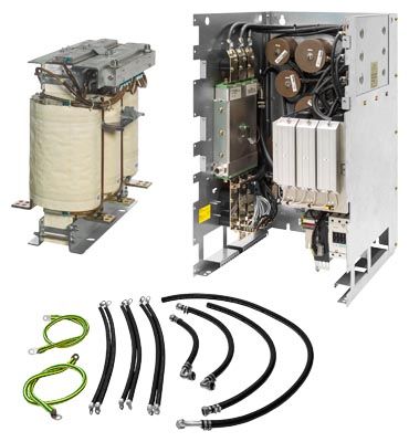
The Active Interface Module essentially comprises a liquid-cooled filter reactor and a liquid-cooled filter module. The filter module contains a Clean Power Filter with basic RI suppression, the pre-charging circuit for the Active Line Module, the line voltage sensing circuit and monitoring sensors.
A bypass contactor is provided separately. Active Interface Modules are used in conjunction with Active Line Modules.
Liquid-cooled Active Interface Modules cannot be supplied for all liquid-cooled Active Line Modules. Where they are not available, air-cooled Active Interface Modules can be ordered instead.
Дизайн
Active Interface Modules have the following interfaces as standard:
- 1 line supply connection
- 1 load connection
- 1 connection for the 24 V DC electronics power supply
- 1 connection for the external 230 V AC supply
- 1 DRIVE‑CLiQ socket (on VSM10 Voltage Sensing Module)
- 1 connection for pre-charging circuit
- 1 PE connection
- 2 coolant connections
The scope of supply of the Active Interface Modules includes:
- Liquid-cooled filter reactor
- Liquid-cooled filter module
- Connection kit (cables and hoses)
- DRIVE‑CLiQ cable for the connection between Active Interface Module and Active Line Module
- 2 seals for coolant connections
- 1 set of warning labels in 30 languages
(BG, CN, CZ, DE, DK, EE, ES, FI, FR, GB, GR, HU, IE, IS, IT, JP, KR, LT, LV, MT, NL, NO, PL, PT, RO, RU, SE, SI, SK, TR)
Интеграция

Connection example of liquid-cooled Active Interface Module with external bypass contactor
Технические данные
Line voltage 380 ... 480 V 3 AC
Active Interface Module
6SL3305-7TE41-4AA3
Suitable for Active Line Module
- Rated power at 400 V
kW
900/630
- Liquid-cooled
6SL3335-7TE41-4AA3
6SL3335-7TE41-0AA3Rated current
A
1405
Bypass contactor 1)
3WL1116-2BB34-4AN2-Z
Z = C22 2)Current demand
- 24 V DC auxiliary power supply
A
0.17
- 230 V 2 AC
- Inrush current
A
1.0
- Holding current
A
0.1
DC link capacitance
of the drive line-up, max. 3)
μF
230400
Coolant volume flow
l/min
16
Pressure drop, typ.
for volume flow
Pa
70000
Sound pressure level LpA
(1 m) at 50/60 Hz
dB
71/71
Frame size
JIL
Filter reactor
Power loss 4)
- At 50 Hz 400 V
kW
8.6
- At 60 Hz 460 V
kW
8.6
- Dissipated to ambient air
kW
0.9
Liquid volume
- Of integrated reactor cooler
dm3
0.6
- Of hoses supplied
dm3/m
0.285
Coolant volume flow
l/min
8
Pressure drop, typ.
for volume flowPa
70000
Heat exchanger material
Aluminum
Line/load connection
L1, L2, L3 / U2, V2, W2
Flat connector for M12 screws
PE/GND connection
M10 stud
- Conductor cross section, max. (IEC)
mm2
1 × 240
Degree of protection
IP00
Dimensions
- Width
mm (in)
373 (14.7)
- Height
mm (in)
716 (28.2)
- Depth
mm (in)
575 (22.6)
Weight, approx.
kg (lb)
299 (659)
Filter module
Power loss 4)
- At 50 Hz 400 V
kW
3.6
- At 60 Hz 460 V
kW
3.6
- Dissipated to ambient air
kW
0.15
Liquid volume
dm3
1
Heat exchanger material
Aluminum
PE/GND connection
Flat connector for M8 screw
- Conductor cross section, max. (IEC)
mm2
2 × 120
Degree of protection
IP00
Dimensions
- Width
mm (in)
511 (20.1)
- Height
mm (in)
840 (33.1)
- Depth
mm (in)
574 (22.6)
Weight, approx.
kg (lb)
110 (243)
1) The bypass contactor is not included in the scope of supply.
2) The breakers must always be switched ON and OFF by the sequence control. An interlocking set 3WL9111‑0BA21‑0AA0 as described in Catalog LV 10 should be provided for the bypass contactor to exclude the risk of unintentional manual operation. Manual operation bypasses the pre-charging circuit and can therefore destroy the Active Line Module.
3)Information on higher capacities is included in the SINAMICS Low Voltage Engineering Manual.
4) The specified power loss represents the maximum value at 100% utilization. The value is lower under normal operating conditions. To ensure safe dissipation of the minor power loss released to the ambient air, it is important to follow the instructions pertaining to control cabinet installation in the SINAMICS Low Voltage Engineering Manual.
Line voltage 500 ... 690 V 3 AC
Active Interface Modules
6SL3305-7TG37-4AA3
6SL3305-7TG41-0AA3
6SL3305-7TG41-3AA3
6SL3305-7TG41-6AA3
Suitable for Active Line Module
- Rated power at 690 V
kW
800
900/1100
1400
1700
- Liquid-cooled
6SL3335-7TG37-4AA3
6SL3335-7TG38-1AA3
6SL3335-7TG41-0AA36SL3335-7TG41-3AA3
6SL3335-7TG41-6AA3
Rated current
A
735
1025
1270
1560
Bypass contactor 1)
3RT1476-6AP36
(3 units)3WL1212-4BB34-4AN2-Z
C22 2)3WL1216-4BB34-4AN2-Z
C22 2)3WL1216-4BB34-4AN2-Z
C22 2)Current demand
- 24 V DC auxiliary power supply
A
0.17
0.17
0.17
0.17
- 230 V 2 AC
- Inrush current
A
1.0
1.0
1.0
1.0
- Holding current
A
0.1
0.1
0.1
0.1
DC link capacitance
of the drive line-up, max. 3)
μF
153600
153600
153600
210000
Coolant volume flow
l/min
10
16
16
16
Pressure drop, typ.
for volume flow
Pa
70000
70000
70000
70000
Sound pressure level LpA
(1 m) at 50/60 Hz
dB
71/71
71/71
71/71
71/71
Frame size
JIL
JIL
JIL
JIL
Filter reactor
Power loss 4)
- At 50 Hz 690 V
kW
5.5
6.2
9.3
11.0
- At 60 Hz 575 V
kW
5.5
6.2
9.3
11.0
- Dissipated to ambient air
kW
0.5
0.6
0.95
1.15
Liquid volume
- Of integrated reactor cooler
dm3
0.6
0.6
0.6
0.6
- Of hoses supplied
dm3/m
0.285
0.285
0.285
0.285
Coolant volume flow
l/min
10
10
10
8
Pressure drop, typ.
for volume flowPa
70000
70000
70000
70000
Heat exchanger material
Aluminum
Aluminum
Aluminum
Aluminum
Line/load connection
L1, L2, L3 / U2, V2, W2
Flat connector for M12 screws
Flat connector for M12 screws
Flat connector for M12 screws
Flat connector for M12 screws
PE/GND connection
M10 stud
M10 stud
M10 stud
M10 stud
- Conductor cross section, max. (IEC)
mm2
1 × 240
1 × 240
1 × 240
1 × 240
Degree of protection
IP00
IP00
IP00
IP00
Dimensions
- Width
mm (in)
358 (14.1)
440 (17.32)
440 (17.32)
440 (17.32)
- Height
mm (in)
680 (26.8)
705 (27.8)
705 (27.8)
705 (27.8)
- Depth
mm (in)
575 (22.6)
575 (22.6)
575 (22.6)
580 (22.8)
Weight, approx.
kg (lb)
324 (714)
365 (805)
365 (805)
460 (1014)
Filter module
Power loss 4)
- At 50 Hz 690 V
kW
4.0
5.0
5.0
7.5
- At 60 Hz 575 V
kW
4.0
5.0
5.0
7.5
- Dissipated to ambient air
kW
0.15
0.15
0.15
0.15
Liquid volume
dm3
1
1
1
1
Heat exchanger material
Aluminum
Aluminum
Aluminum
Aluminum
PE/GND connection
Flat connector for M8 screw
Flat connector for M8 screw
Flat connector for M8 screw
Flat connector for M8 screw
- Conductor cross section, max. (IEC)
mm2
2 × 120
2 × 120
2 × 120
2 × 120
Degree of protection
IP00
IP00
IP00
IP00
Dimensions
- Width
mm (in)
511 (20.1)
511 (20.1)
511 (20.1)
511 (20.1)
- Height
mm (in)
840 (33.1)
840 (33.1)
840 (33.1)
840 (33.1)
- Depth
mm (in)
574 (22.6)
574 (22.6)
574 (22.6)
574 (22.6)
Weight, approx.
kg (lb)
110 (243)
110 (243)
110 (243)
110 (243)
1) The bypass contactor is not included in the scope of supply.
2) The breakers must always be switched ON and OFF by the sequence control. An interlocking set 3WL9111‑0BA21‑0AA0 as described in Catalog LV 10 should be provided for the bypass contactor to exclude the risk of unintentional manual operation. Manual operation bypasses the pre-charging circuit and can therefore destroy the Active Line Module.
3)Information on higher capacities is included in the SINAMICS Low Voltage Engineering Manual.
4) The specified power loss represents the maximum value at 100% utilization. The value is lower under normal operating conditions. To ensure safe dissipation of the minor power loss released to the ambient air, it is important to follow the instructions pertaining to control cabinet installation in the SINAMICS Low Voltage Engineering Manual.