
- Каталог оборудования Siemens
- Каталог продуктов Siemens Industry
- Приводная техника
- Преобразователи
- Стандартные преобразователи
- Общая информация о базовых преобразователях SINAMICS V
- Преобразователи частоты общего назначения SINAMICS G
- Преобразователи частоты SINAMICS G110
- Компактные преобразователи SINAMICS G120C
- Преобразователи для насосов, вентиляторов,компрессоров SINAMICS G120P
- Обзор
- Введение
- Преобразователи для насосов, вентиляторов, компрессоров SINAMICS G120P
- Integrated Drive Systems
- SINAMICS G120P, built-in and wall-mounted units, IP20/IP54/IP55
- SINAMICS G120P Cabinet, cabinet units, IP20 to IP54
- Selection and engineering tools
- Инженерные инструменты
- Services and documentation
- Инструменты проектирования
- Сервис и документация
- Стандартные преобразователи SINAMICS G120
- SINAMICS G110M distributed inverters
- Преобразователь частоты SINAMICS G110D для распределенной периферии
- Преобразователи частоты SINAMICS G120D
- Преобразователи SINAMICS G130 формат шасси
- Преобразователь частоты SINAMICS G150 шкафного исполнения
- SINAMICS G180
- Высокопроизводительные преобразователи SINAMICS S
- MICROMASTER
- SIPLUS POSMO A
- SIMODRIVE POSMO
- LOHER DYNAVERT Drive System
- Преобразователи на среднее напряжение
- Преобразователи постоянного тока
- Стандартные преобразователи
- Двигатели переменного тока
- Generators
- Мотор-редукторы
- Flender Gear Units
- Couplings
- Инструментальное программное обеспечение
- Дополнительные компоненты
- Преобразователи
- Техника автоматизации
- Energy
- Автоматизация и безопасность зданий
- Низковольтная коммутационная техника
- Технология безопасности
- Системные решения и продукты для отраслей
- Сервис
- Приводная техника
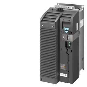
PM240 Power Modules
- Заказные данные (42)
- Информационные материалы
Информационные материалы

SINAMICS G120 PM240 Power Module, frame size FSF
PM240 Power Modules have an integrated braking chopper.
The permissible cable lengths between inverter and motor are limited. Longer cables can be used if output reactors are connected (see load-side power components).
Line reactors are available to minimize line harmonics as well as voltage and current peaks (see line-side components).
Power Modules with integrated line filter class A are suitable for connection to TN systems. Power Modules without integrated line filter can be connected to grounded TN/TT systems and non-grounded IT systems.
Note:
Shield plates and shield connection kits are available. These can be used in the wiring installation for the Control Units and Power Modules to ensure that it complies with EMC guidelines.
For further information, see Shield connection kits and shield plates for Control Units and Power Modules in section Supplementary system components.Характеристика
Derating data, PM240 Power Modules
Pulse frequency
Rated power
Rated output current in A
for a pulse frequency of
400 V
460 V
kW
hp
2 kHz
4 kHz
6 kHz
8 kHz
90
125
–
178
151.3
124.6
110
150
205 1)
178
–
–
132
200
250 1)
202
–
–
1) The pulse frequency can only be switched over from 4 kHz (default) to 2 kHz for the low overload (LO) duty cycle.
Ambient temperature

Low overload (LO) for PM240 Power Modules, frame size FSF
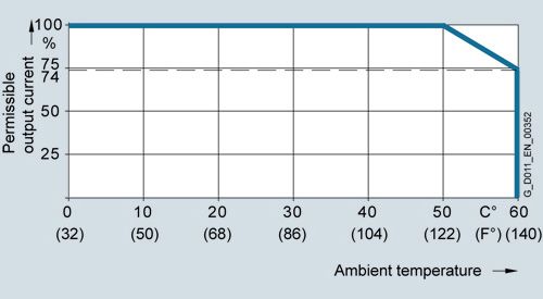
High overload (HO) for PM240 Power Modules, frame size FSF
Note:
The operating temperature ranges of the Control Units should be taken into account. The temperature ranges are specified in the section Technical specifications under Control Units.
Installation altitude
Permissible line supplies depending on the installation altitude
• Installation altitude up to 2000 m above sea level
- Connection to every supply system permitted for the inverter
• Installation altitudes between 2000 m and 4000 m above sea level
- Connection to a TN system with grounded neutral point
- TN systems with grounded line conductor are not permitted
- The TN line system with grounded neutral point can also be supplied using an isolation transformer
- The phase-to-phase voltage does not have to be reduced
Note:
The connected motors, power elements and components must
be considered separately.

Permissible output current as a function of the installation altitude for PM240 Power Modules, frame size FSF
Интеграция
All PM240 Power Modules have the following connections and interfaces:
- PM‑IF interface to connect the Power Module to the Control Unit. The Power Module also supplies power to the Control Unit using an integrated power supply
- Motor connection using screw terminals or screw studs
- 2 PE/protective conductor connections
- Terminals DCP/R1 and R2 for connection of an external braking resistor
- Control for the Brake Relay for controlling a motor brake

Connection diagram for PM240 Power Module with or without integrated line filter class A
Available optional power and DC link components
The following line-side power components, DC link components and load-side power components are optionally available in the appropriate frames sizes for the Power Modules:
Frame size
FSF
PM240 Power Module with integrated braking chopper
Line-side power components
Line filter class A
F/S 1)
Line reactor
S
DC link components
Braking resistor
S
Load-side power components
Output reactor
S
Sine-wave filter
S
S = Lateral mounting
F = Power Modules available with and without integrated filter class A
1) PM240 Power Modules, frame size FSF, 110 kW and higher, are available only without an integrated filter class A. An optional line filter class A for lateral mounting is available instead.
General design information
- With lateral mounting, the line-side components have to be mounted on the left side of the inverter,
and the load-side components on the right side. - Braking resistors have to be mounted directly on the control cabinet wall due to heating issues.
Recommended installation combinations of the inverter and optional power and DC link components
Power Module
Lateral mounting
Frame size
Left of the inverter
(for line-side power components)Right of the inverter
(for load-side power components and DC link components)FSF
Line filter and/or
line reactorOutput reactor or
sine-wave filter and/or
braking resistorMaximum permissible cable lengths from the motor to the inverter when using output reactors or sine-wave filters depending on the voltage range
The following load-side power components in the appropriate frame sizes are optionally available for the Power Modules and result in the following maximum cable lengths:
PM240 Power Module, frame size FSF, with integrated braking chopper
Maximum permissible motor cable lengths (shielded/unshielded) in m
Without output reactor/sine-wave filter
50/100
With optional output reactor
200/300
With optional sine-wave filter
200/300
Derating data
The following inverter output currents can still be achieved with long motor cables without output reactor and sine-wave filter.
Derating for PM240 Power Modules, frame size FSF, with a shielded motor cable.
Rated power 1)
Frame size
Rated output current Irated 2)
Base-load current IH
Motor connection cross-section
Current derating
of the output current as a % of the base-load current for the cable lengths (MOTION-CONNECT)
400 V
460 V
kW
hp
A
A
mm2
50 m
100 m
150 m
200 m
90
125
FSF
178
145
95
100 %
100 %
100 %
95 %
1) Rated power based on the rated output current Irated. The rated output current Irated is based on the duty cycle for low overload (LO).
2) The rated output current Irated is based on the duty cycle for low overload (LO). These current values are valid for 400 V and are specified on the rating plate of the Power Module.
Чертеж
PM240 Power Modules, degree of protection IP20
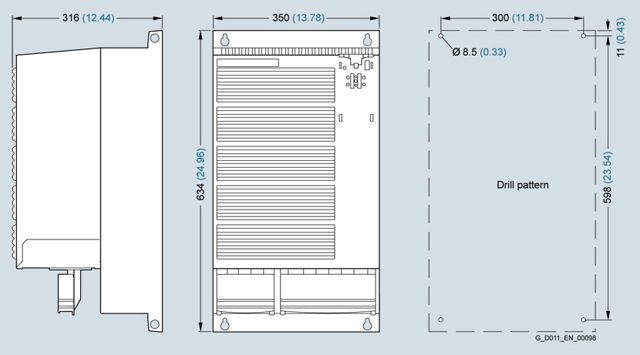
Principle dimension drawing and drill pattern for PM240 Power Modules, frame size FSF, degree of protection IP20, without integrated line filter class A

Principle dimension drawing and drill pattern for PM240 Power Modules, frame size FSF, degree of protection IP20, with integrated line filter class A
Increased depth:
• When the CU230P-2 Control Unit is plugged on, the depth increases by 58 mm (2.28 in).
• When the IOP is plugged on, the depth increases by a further 25 mm (0.98 in)
• When the BOP‑2 is plugged on, the depth increases by a further 15 mm (0.59 in)
Технические данные
General technical specifications
Power Modules
PM240
System operating voltage
380 ... 480 V ±10 % 3 AC
Grid requirement
Short-circuit power RSC>25
>100 line reactor recommended
Input frequency
47 ... 63 Hz
Output frequency
- Control mode V/f
0 ... 550 Hz
- Control type Vector
0 ... 240 Hz
Pulse frequency
75 kW (HO): 4 kHz
as of 90 kW (HO): 2 kHz
Higher pulse frequencies up to 16 kHz, see derating data
Power factor λ
0.7 ... 0.85
Offset factor cos φ
0.95
Inverter efficiency
95 ... 98 %
Output voltage, max.
As % of input voltage
95%
Overload capability
- Low overload
(LO)
Note:
When the overload capability is used, the base-load current IL is not reduced.
90 kW (LO):
1.5 × base-load current IL (i. e. 150 % overload) for 3 s plus 1.1 × base-load current IL (i. e. 110 % overload) for 57 s within a cycle time of 300 s110 kW and higher (LO):
1.5 × base-load current IL (i. e. 150 % overload) for 1 s plus 1.1 × base-load current IL (i. e. 110 % overload) for 59 s within a cycle time of 300 s- High overload
(HO)
Note:
When the overload capability is used, the base-load current IH is not reduced.
75 kW (HO):
2 × base-load current IH (i. e. 20 % overload) for 3 s plus 1.5 × base-load current IH (i. e. 150 % overload) for 57 s within a cycle time of 300 s90 kW and higher (HO):
1.6 × base-load current IH (i. e. 160 % overload) for 3 s plus 1.36 × base-load current IH (i. e. 136 % overload) for 57 s within a cycle time of 300 sElectromagnetic compatibility
- Devices without line filter
- Devices with line filter class A for compliance with conducted and radiated interference requirements of Category C2
Possible braking methods
- DC braking
- Dynamic braking with integrated braking module
Degree of protection
IP20
Operating temperature
- Low overload
(LO)
0 ... 40 °C (32 ... 104 °F) without derating
>40 ... 60 °C (>104 ... 140 °F) see derating characteristics- High overload
(HO)
0 ... 50 °C (32 ... 122 °F) without derating
>50 ... 60 °C (>122 ... 140 °F) see derating characteristicsStorage temperature
-40 ... +70 °C (-40 ... +158 °F)
Relative humidity
<95 %, condensation not permissible
Cooling
Internal ventilation, power units with increased air cooling by built-in fans
Installation altitude
Up to 1000 m (3281 ft) above sea level without derating,
> 1000 m (3281 ft) see derating characteristicsProtection functions
- Undervoltage
- Overvoltage
- Overcurrent/overload
- Overtemperature
- Ground fault
- Short-circuit
- Stall protection
- Motor blocking protection
- Motor overtemperature
- Inverter overtemperature
- Parameter locking
Short-Circuit Current Rating SCCR
(Short-Circuit Current Rating) 1)
65 kA
Compliance with standards
UL, cUL, CE, RCM, SEMI F47
CE marking
According to Low Voltage Directive 2014/35/EU, EMC Directive 2014/30/EU
1) Applies to industrial control panel installations acc. to NEC Article 409 or UL 508A/508C.
PM240 Power Modules
Line voltage 380 ... 480 V 3 AC
PM240 Power Modules
Without integrated line filter
6SL3224-0BE37-5UA0
6SL3224-0BE38-8UA0
6SL3224-0BE41-1UA0
With integrated line filter
6SL3224-0BE37-5AA0
–
–
Output current
at 50 Hz 400 V 3 AC
- Rated current Irated1)
A
178
205
250
- Base-load current IL1)
A
178
205
250
- Base-load current IH2)
A
145
178
205
- Maximum current Imax
A
290
308
375
Rated power
- Based on IL
kW (hp)
90 (125)
110 (148)
132 (200)
- Based on IH
kW (hp)
75 (100)
90 (125)
110 (148)
Rated pulse frequency
kHz
4
2
2
Efficiency η
>0.97
>0.97
>0.97
Power loss 3)
at rated current
kW
2.376
2.274
2.964
Cooling air requirement
m3/s (ft3/s)
0.15 (5.3)
0.15 (5.3)
0.15 (5.3)
Sound pressure level
LpA (1 m/3.28 ft)
dB
<65
<65
<65
24 V DC power supply
for Control Unit
A
1
1
1
Rated input current 4)
- With line reactor
A
186
210
250
- Without line reactor
A
204
245
299
Length of cable to braking resistor, max.
m (ft)
15 (49)
15 (49)
15 (49)
Line supply connection
U1/L1, V1/L2, W1/L3
M8 screw studs
M8 screw studs
M8 screw studs
- Conductor cross-section
mm2
25 ... 120
25 ... 120
25 ... 120
Motor connection
U2, V2, W2
M8 screw studs
M8 screw studs
M8 screw studs
- Conductor cross-section
mm2
25 ... 120
25 ... 120
25 ... 120
DC link connection, connection for braking resistor
DCP/R1, DCN, R2
M8 screw studs
M8 screw studs
M8 screw studs
- Conductor cross-section
mm2
25 ... 120
25 ... 120
25 ... 120
PE connection
On housing with M8 screw
On housing with M8 screw
On housing with M8 screw
Motor cable length 5), max.
- Shielded
m (ft)
50 (164)
50 (164)
50 (164)
- Unshielded
m (ft)
100 (328)
100 (328)
100 (328)
Degree of protection
IP20
IP20
IP20
Dimensions
- Width
mm (in)
350 (13.78)
350 (13.78)
350 (13.78)
- Height
- Without integrated line filter
mm (in)
634 (24.96)
634 (24.96)
634 (24.96)
- With integrated line filter
mm (in)
934 (36.77)
–
–
- Depth
- Without operator panel
mm (in)
316 (12.44)
316 (12.44)
316 (12.44)
- With operator panel, max.
mm (in)
387 (15.24)
387 (15.24)
387 (15.24)
Frame size
FSF
FSF
FSF
Weight, approx.
- Without integrated line filter
kg (lb)
36 (79.4)
39 (86)
39 (86)
- With integrated line filter
kg (lb)
52 (115)
–
–
1) The rated output current Irated and the base-load current IL are based on the duty cycle for low overload (LO).
2) The base-load current IH is based on the duty cycle for high overload (HO).
3) Typical values. You can find additional information on the Internet at https://support.industry.siemens.com/cs/document/94059311
4) The input current depends on the motor load and line impedance. The input currents apply for rated power loading (based on Irated) for a line impedance corresponding to uK = 1 %. These current values without line reactor are specified on the rating plate of the Power Module.
5) Max. motor cable length 25 m (82 ft) (shielded) for PM240 Power Modules with integrated line filter to maintain the limit values acc. to EN 61800‑3 Category C2.