
- Каталог оборудования Siemens
- Каталог продуктов Siemens Industry
- Приводная техника
- Преобразователи
- Стандартные преобразователи
- Общая информация о базовых преобразователях SINAMICS V
- Преобразователи частоты общего назначения SINAMICS G
- Преобразователи частоты SINAMICS G110
- Компактные преобразователи SINAMICS G120C
- Преобразователи для насосов, вентиляторов,компрессоров SINAMICS G120P
- Обзор
- Введение
- Преобразователи для насосов, вентиляторов, компрессоров SINAMICS G120P
- Integrated Drive Systems
- SINAMICS G120P, built-in and wall-mounted units, IP20/IP54/IP55
- SINAMICS G120P Cabinet, cabinet units, IP20 to IP54
- Selection and engineering tools
- Инженерные инструменты
- Services and documentation
- Инструменты проектирования
- Сервис и документация
- Стандартные преобразователи SINAMICS G120
- SINAMICS G110M distributed inverters
- Преобразователь частоты SINAMICS G110D для распределенной периферии
- Преобразователи частоты SINAMICS G120D
- Преобразователи SINAMICS G130 формат шасси
- Преобразователь частоты SINAMICS G150 шкафного исполнения
- SINAMICS G180
- Высокопроизводительные преобразователи SINAMICS S
- MICROMASTER
- SIPLUS POSMO A
- SIMODRIVE POSMO
- LOHER DYNAVERT Drive System
- Преобразователи на среднее напряжение
- Преобразователи постоянного тока
- Стандартные преобразователи
- Двигатели переменного тока
- Generators
- Мотор-редукторы
- Flender Gear Units
- Couplings
- Инструментальное программное обеспечение
- Дополнительные компоненты
- Преобразователи
- Техника автоматизации
- Energy
- Автоматизация и безопасность зданий
- Низковольтная коммутационная техника
- Технология безопасности
- Системные решения и продукты для отраслей
- Сервис
- Приводная техника
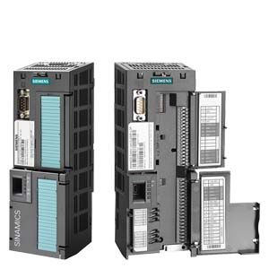
CU230P-2 Control Units
- Заказные данные (3)
- Аксессуары (2)
- Информационные материалы
Информационные материалы

Example: CU230P-2 PN Control Unit
The CU230P-2 Control Units are designed for drives with integrated technological functions for pump, fan and compressor applications. The I/O interface, the fieldbus interfaces and the additional software functions optimally support these applications.
Note:
Shield plates and shield connection kits are available. These can be used in the wiring installation for the Control Units and PM230/PM240 Power Modules to ensure that it complies with EMC guidelines.
For further information, see Shield connection kits and shield plates for Control Units and Power Modules in section Supplementary system components.PM330 Power Modules are supplied with the accessories needed to create an EMC-compliant wiring installation for Control Units and Power Modules. The Control Unit mounting surface on the Power Modules has mounting slots for shielding terminals.
Дизайн
CU230P‑2 HVAC, CU230P‑2 DP and CU230P‑2 PN Control Units

Example: CU230P‑2 Control Unit with open and closed terminal covers
Terminal No.
Signal
Features
Digital inputs (DI) – Standard
69
DI COM
Reference potential for digital inputs
5 ... 8,
16.17DI0 … DI5
Freely programmable
isolated, inputs in compliance with IEC 61131-2Digital outputs (DO)
18
DO0, NC
Relay output 1
NC contact (5 A, 30 V DC or 2 A, 250 V AC) 1)19
DO0, NO
Relay output 1
NO contact (5 A, 30 V DC or 2 A, 250 V AC)20
DO0, COM
Relay output 1
Common contact (5 A, 30 V DC or 2 A, 250 V AC) 1)21
DO1, NO
Relay output 2
NO contact (0.5 A, 30 V DC)22
DO1, COM
Relay output 2
Common contact (0.5 A, 30 V DC)23
DO2, NC
Relay output 3
NC contact (5 A, 30 V DC or 2 A, 250 V AC) 1)24
DO2, NO
Relay output 3
NO contact (5 A, 30 V DC or 2 A, 250 V AC)25
DO2, COM
Relay output 3
Common contact (5 A, 30 V DC or 2 A, 250 V AC) 1)Analog inputs (AI)
3
AI0+
Differential input, switchable between current and voltage
Value range: 0 ... 10 V, -10 ... +10 V, 0/2 ... 10 V, 0/4 ... 20 mA4
AI0-
10
AI1+
Differential input, switchable between current and voltage
Value range: 0 ... 10 V, -10 ... +10 V, 0/2 ... 10 V, 0/4 ... 20 mA11
AI1-
50
AI2+
Non-isolated input, switchable between current and temperature sensors, type Pt1000/LG-Ni1000
Value range: 0/4 ... 20 mA,
Pt1000: -50 ... +250 °C
LG-Ni1000: -50 ... +150 °C51
GND
Reference potential of the AI2/internal electronics ground
52
AI3+
Non-isolated input for temperature sensors, type Pt1000/LG-Ni1000
value range:
- Pt1000: -50 ... +250 °C
- LG-Ni1000: -50 ... +150 °C53
GND
Reference potential of the AI3/internal electronics ground
Analog outputs (AO)
12
AO0+
Non-isolated output
Freely programmable
Value range: 0 ... 10 V; 0/4 ... 20 mA13
GND
Reference potential of the AO0/internal electronics ground
26
AO1+
Non-isolated output
Freely programmable
Value range: 0 ... 10 V; 0/4 ... 20 mA27
GND
Reference potential of the AO1/internal electronics ground
Motor temperature sensor interface
14
T1 MOTOR
Positive input for motor temperature sensor
Type: PTC, Pt1000, KTY sensor, bimetal15
T2 MOTOR
Negative input for motor temperature sensor
Power supply
9
+24 V OUT
Power supply output
24 V DC, max. 100 mA28
GND
Reference potential of the power supply/internal electronics ground
1
+10 V OUT
Power supply output
10 V DC ±0.5 V, max. 10 mA2
GND
Reference potential of the power supply/internal electronics ground
31
+24 V IN
Power supply input
20.4 ... 28.8 V DC, max. 1500 mA32
GND IN
Reference potential of the power supply input
35
+10 V OUT
Power supply output
10 V DC ±0.5 V, max. 10 mA36
GND
Reference potential of the power supply/internal electronics ground
1) The following applies to systems complying with UL: A maximum of 3 A, 30 V DC or 2 A, 250 V AC may be connected via terminals 18 / 20 (DO0 NC) and 23 / 25 (DO2 NC).
Функции
Below is a list of functions sorted according to the following categories:
Control modes
- Linear and quadratic torque characteristic for fluid flow and positive displacement machines
- ECO mode for additional energy saving in U/f control mode
- Sensorless vector control for sophisticated control tasks and high-output motors
Connections
- 2 analog inputs (current/voltage can be selected) to directly connect pressure/level sensors
- 2 additional analog inputs to connect Pt1000/LG‑Ni1000 temperature sensors
- Direct control of valves and flaps using two 230 V AC relays
Interfaces
- PROFINET, EtherNet/IP, PROFIBUS, USS, BACnet MS/TP, FLN P1, and Modbus-RTU communication
Software functions
- Automatic restart function after power failure
- Automatic restart
- Flying restart
- Skip frequencies
- 1 PID controller for the closed-loop control of the motor speed as process controller for temperature, pressure, air quality or levels
- 3 freely-programmable PID controllers
- Hibernation mode
- Load check function to monitor belts and flow
- Cascade connection
- Multi-zone controller
- Essential service mode
- Real time clock with three time generators
IOP wizards for special applications with and without PID controller, such as
- Pumps: Positive displacement (constant load torque) and centrifugal pumps (quadratic load torque)
- Fans: Radial and axial fans (quadratic load torque)
- Compressors: Positive displacement (constant load torque) and fluid flow machines (quadratic load torque)
Интеграция

Connection diagram for the CU230P‑2 Control Unit series
More information about the interfaces of the Control Unit is available on the Internet at
https://support.industry.siemens.com/cs/document/109477360
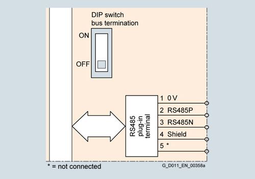
Communication interface USS, Modbus RTU, BACnet MS/TP, FLN P1 for CU230P‑2 HVAC
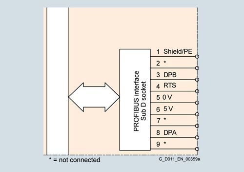
PROFIBUS DP communication interface
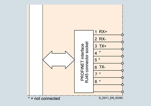
PROFINET communication interface, EtherNet/IP
Технические данные
Control Unit
CU230P‑2 HVAC
CU230P‑2 DP
CU230P‑2 PN
6SL3243-0BB30-1HA3
6SL3243-0BB30-1PA3
6SL3243-0BB30-1FA0
Electrical specifications
Operating voltage
24 V DC via the Power Module or by connecting to an external 20.4 ... 28.8 V DC power supply
Current consumption, max.
0.5 A
Protective insulation
PELV according to EN 50178
Protective separation from the line supply using double/reinforced insulationPower loss, max.
5 W
Interfaces
Digital inputs – Standard
6 isolated inputs, optically isolated;
free reference potential (own potential group)NPN/PNP logic can be selected using the wiring
- Switching level: 0 → 1
11 V
- Switching level: 1 → 0
5 V
- Input current
5.5 mA
Digital outputs
3 relays
- 2 relay changeover contacts
250 V AC, 2 A (inductive load)
30 V DC, 5 A (ohmic load)
The following applies to UL-compliant installations: A maximum of 3 A, 30 V DC or 2 A, 250 V AC may be connected via terminals 18 / 20 (DO0 NC) and 23 / 25 (DO2 NC).- 1 relay NO contact
30 V DC, 0.5 A (ohmic load)
Analog inputs
Analog inputs are protected against inputs in a voltage range of ± 30 V and have a common-mode voltage in the ± 15 V range
- 2 differential inputs
Switchable with DIP switch between voltage and current:
-10 ... +10 V, 0/4 ... 20 mA, 12-bit resolutionThese differential inputs can be configured as additional digital inputs.
Switching thresholds:
0 → 1: Rated voltage 4 V
1 → 0: Rated voltage 1.6 V- 1 non-isolated input
Switchable with DIP switch between 0/4 ... 20 mA current and temperature sensor type Pt1000/LG-Ni1000,
12-bit resolution- 1 non-isolated input
Temperature sensor, type Pt1000/LG‑Ni1000,
12-bit resolutionAnalog outputs
The analog outputs have short circuit protection
- 2 non-isolated outputs
Switchable between voltage and current using parameter setting:
0 ... 10 V, 0/4 ... 20 mAVoltage mode: 10 V, min. burden 10 kΩ
Current mode: 20 mA, max. burden 500 ΩPTC/KTY interface
1 motor temperature sensor input,
connectable sensors PTC, Pt1000, KTY and bimetal,
accuracy ±5 °CBus interface
Fieldbus protocols
- USS
- Modbus RTU
- BACnet MS/TP
- FLN P1 (switchable using software)
- PROFIBUS DP
- PROFINET
- EtherNet/IP
- ODVA AC drive
- SINAMICS profile
Profile
–
- PROFIdrive
- PROFIdrive
- PROFIenergy
Hardware
Plug-in terminal, insulated,
USS: max. 187.5 kBaud
Modbus RTU: 19.2 kBaud,
Bus terminating resistor that can be switched in9-pin SUB-D socket, insulated,
max. 12 Mbit/s
Slave address can be set using DIP switches2 × RJ45, PROFIdrive profile V4.1, device name can be stored on the device
Max. 100 Mbit/s (full duplex)
Control Unit
CU230P‑2 HVAC
CU230P‑2 DP
CU230P‑2 PN
6SL3243-0BB30-1HA3
6SL3243-0BB30-1PA3
6SL3243-0BB30-1FA0
Tool interfaces
Memory card
SINAMICS SD card
Operator panels
- Intelligent Operator Panel IOP
Can be directly plugged on
- Basic Operator Panel BOP-2
Can be directly plugged on
- Blanking cover
Required when no operator panel is plugged in order to achieve degree of protection IP55 on PM230 Power Modules degree of protection IP55/UL Type 12
PC interface
USB (connection via PC inverter connection kit 2)
Open-loop/closed-loop control techniques
U/f linear/quadratic/parameterizable
✓
U/f with flux current control (FCC)
✓
U/f ECO; linear/quadratic
✓
Vector control, sensorless
✓
Software functions
Setpoint input
✓
Fixed frequencies
16, parameterizable
JOG
✓
Digital motorized potentiometer (MOP)
✓
Ramp smoothing
✓
Extended ramp-function generator (with ramp smoothing OFF3)
✓
Slip compensation
✓
Signal interconnection with BICO technology
✓
Free function blocks (FFB)
for logical and arithmetic operations
✓
Switchable drive data sets (DDS)
✓ (4)
Switchable command data sets (CDS)
✓ (4)
Flying restart
✓
Automatic restart
after line supply failure or operating fault (AR)
✓
Technology controller (internal PID)
✓
Hibernation mode
with internal/external PID controller
✓
Belt monitoring
with and without sensor (load torque monitoring)
✓
Dry-running/overload protection monitoring
(load torque monitoring)
✓
Thermal motor protection
✓ (I2t, sensor: PTC/Pt1000/KTY/bimetal)
Thermal inverter protection
✓
Motor identification
✓
Auto-ramping (Vdcmax controller)
✓
Kinetic buffering (Vdcmin controller)
✓
Possible braking functions
- DC braking (PM230, PM240, PM330, Cabinet)
- Dynamic braking with integrated braking chopper and external braking resistor (PM240)
- Dynamic braking with optional Braking Module and braking resistor (PM330, Cabinet)
Control Unit
CU230P‑2 HVAC
CU230P‑2 DP
CU230P‑2 PN
6SL3243-0BB30-1HA3
6SL3243-0BB30-1PA3
6SL3243-0BB30-1FA0
Mechanical specifications and ambient conditions
Degree of protection
IP20
Signal cable cross-section
0.15 ... 1.5 mm2 (AWG28 ... AWG16)
Operating temperature
For CU230P‑2 HVAC/DP: -10 ... 60 °C (14 ... 140 °F)
For CU230P‑2 PN:-10 ... 55 °C (14 ... 131 °F)
With IOP/BOP‑2: 0 ... 50 °C (32 ... 122 °F)
Derating of 3 K/1000 m applies to Control Units as of an installation altitude of 1000 m above sea level.
Storage temperature
-40 ... +70 °C (-40 ... +158 °F)
Relative humidity
<95 %, condensation not permissible
Dimensions
- Width
73 mm (2.87 in)
- Height
199 mm (7.83 in)
- Depth
65.5 mm (2.58 in)
Weight, approx.
0.61 kg (1.34 lb)