
- Каталог оборудования Siemens
- Каталог продуктов Siemens Industry
- Приводная техника
- Техника автоматизации
- Системы автоматизации
- Промышленные системы автоматизации SIMATIC
- Программируемые контроллеры
- Логические модули LOGO!
- Базовый контроллер
- SIMATIC S7
- S7-1500
- S7-300/ S7-300F/ SIPLUS S7-300
- S7-400/S7-400H/S7-400F/FH
- Demonstration models
- Central processing units
- Signal modules
- Function modules
- Communication
- Connection method
- Racks
- SIPLUS S7-400 racks
- Interface modules
- PS 405/407 power supply
- SIPLUS S7-400 power supplies
- Accessories
- S7-400H
- S7-400F/FH
- Контроллеры для распределенных систем
- Программный контроллер
- Дополнительные компоненты
- Распределенный ввод/вывод
- Система автоматизации SIMATIC TDC
- Программное обеспечение для SIMATIC S7/WinAC
- Программаторы
- SIEMENS Solution Partner
- Test
- Программируемые контроллеры
- Motion Control - система SIMOTION
- Системы автоматизации на базе СЧПУ SINUMERIK
- Система соединителей/ шкафы управления
- Программное обеспечение для систем автоматизации
- Промышленные системы автоматизации SIMATIC
- Системы визуализации SIMATIC HMI
- Системы идентификации
- Промышленные коммуникации SIMATIC NET
- Промышленные аппараты управления SIRIUS
- Промышленные информационные технологии
- Управление на базе РС
- Системы управления процессом
- Контрольно-измерительные приборы
- Анализаторы процесса
- Блоки питания SITOP
- Продукты для специальных требований
- Системы автоматизации
- Energy
- Автоматизация и безопасность зданий
- Низковольтная коммутационная техника
- Технология безопасности
- Системные решения и продукты для отраслей
- Сервис
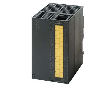
SIPLUS S7-300 SM 326 - Safety Integrated
- Заказные данные (4)
- Аксессуары (16)
- Информационные материалы
Информационные материалы
- Digital outputs for the fail-safe SIMATIC S7 systems
- For connection of solenoid valves, DC contactors and indicator lights
- With integral safety functions for fail-safe operation
- Can be used in fail-safe mode
- Centrally: With S7-31xF-2 DP
- Distributed in ET 200M: With SIMATIC IM 151-7 F-CPU, S7-31xF-2 DP, S7-416F-2 and S7-400F/FH
Note:
SIPLUS extreme products are based on SIMATIC standard products. The contents listed here were taken from the respective standard products. SIPLUS extreme specific information was added.
Область применения
Fail-safe digital output modules are used centrally with SIMATIC S7-31xF-2 DP, and in the ET 200M distributed I/O device together with SIMATIC IM 151-7 F-CPU, S7-31xF-2 DP, S7-416F-2 and S7-400F/FH.
The modules are, for example, suitable for connecting solenoid valves, DC contactors and indicator lights.
In the case of the SM 326 F-DO 10 x DC 24V/2A PP (6ES7 326-2BF10-0AB0), the function "Keep last valid value" can be used optionally in safety mode too. Together with the diagnostics capability of the module, this can be used for cost-optimized implementation of applications in, for example, the area of fire and gas alarm systems (in accordance with EN 54-2/-4 or NFPA72).
Дизайн
Fail-safe digital output modules have the following mechanical features:
- Compact design:
- 2 connections per output for single-channel or redundant actuator control
- Green LEDs for indicating signal states at the outputs
- Green LED for indicating safety operation
- Red LED for group error display
- Connection options for the front connector, protected behind the front door
- Labeling field on the front door
- Simple installation:
installation is the same as for the other I/O modules of the ET 200M - User-friendly wiring via the front connector
- Module width:
- SM 326 F-DO 10 x DC 24V/2A PP (6ES7 326-2BF10-0AB0) single-width (40mm)
- SM 326 F-DO 8 x DC 24V/2A PM (6ES7 326-2BF41-0AB0) double-width (80 mm)
Функции
Failsafe digital output modules convert the internal signal level of the failsafe SIMATIC S7 CPUs into the external signal levels required for the process. The safety functions required for failsafe operation are integrated in the modules.
Технические данные
Order number
6AG1326-2BF10-2AB0
6AG1326-2BF10-2AY0
6AG1326-2BF41-2AB0
6AG1326-2BF41-2AY0
SIPLUS S7-300 SM326F 10 DO
SIPLUS S7-300 SM326 10F-DO
SIPLUS S7-300 SM326F DO8
SIPLUS S7-300 SM326 F DO8 EN50155
Supply voltage
Rated value (DC)
24 V; 1L+
24 V; 1L+
24 V; 1L+
24 V; 1L+
Load voltage L+
● Rated value (DC)
24 V; 2L+, 3L+
24 V; 2L+, 3L+
24 V; 2L+, 3L+
24 V; 2L+, 3L+
Input current
from supply voltage 1L+, max.
100 mA
100 mA
75 mA
75 mA
from load voltage 2L+ (without load), max.
100 mA
100 mA
100 mA
100 mA
from load voltage 3L+ (without load), max.
100 mA
100 mA
100 mA
100 mA
from backplane bus 5 V DC, max.
100 mA
100 mA
100 mA
100 mA
Power loss
Power loss, typ.
6 W
6 W
12 W
12 W
Digital outputs
Number of digital outputs
10
10
8
8
Short-circuit protection
Yes
Yes
Yes
Limitation of inductive shutdown voltage to
L+ (-33 V)
L+ (-33 V)
Switching capacity of the outputs
● on lamp load, max.
5 W
5 W
5 W
5 W
Output voltage
● for signal "1" without series diode, min.
L+ (-1.0 V)
L+ (-1.0 V)
Output current
● for signal "1" rated value
2 A
2 A
2 A
2 A
● for signal "1" permissible range for 0 to 40 °C, min.
7 mA
7 mA
7 mA
7 mA
● for signal "1" permissible range for 0 to 40 °C, max.
2.4 A
2.4 A
2 A; 2 A for horizontal installation, 1 A for vertical installation
2 A; with horizontal installation, 1 A with vertical installation
● for signal "1" permissible range for 40 to 60 °C, min.
7 mA
7 mA
7 mA
7 mA
● for signal "1" permissible range for 40 to 60 °C, max.
2.4 A
2.4 A
1 A; for horizontal installation
1 A; for horizontal installation
● for signal "0" residual current, max.
0.5 mA
0.5 mA
0.5 mA
0.5 mA
Switching frequency
● with resistive load, max.
25 Hz
25 Hz
30 Hz
30 Hz
● with inductive load, max.
25 Hz
25 Hz
2 Hz
2 Hz
● on lamp load, max.
10 Hz
10 Hz
10 Hz
10 Hz
Total current of the outputs (per group)
horizontal installation
— up to 40 °C, max.
10 A
10 A
7.5 A
7.5 A
— up to 60 °C, max.
6 A
6 A
5 A
4 A
vertical installation
— up to 40 °C, max.
5 A
5 A
5 A
5 A
Cable length
● shielded, max.
1 000 m
1 000 m
200 m; 200 m for SIL3, AK 6, Cat 4
200 m; 200 m for SIL3, AK 6, Cat 4
● unshielded, max.
600 m
600 m
200 m
200 m
Interrupts/diagnostics/status information
Alarms
● Diagnostic alarm
Yes
Yes
Yes; Parameterizable
Yes; Parameterizable
Diagnostic messages
● Diagnostic information readable
Yes
Yes
Yes
Yes
Potential separation
Potential separation digital outputs
● between the channels
Yes
Yes
Yes
Yes
● between the channels, in groups of
5
5
4
4
● between the channels and backplane bus
Yes
Yes
Yes
Yes
● between the channels and the power supply of the electronics
Yes
Yes
Yes
Yes
Isolation
Isolation tested with
370V for 1 min
500V AC for 1 min (internal voltage limiting to ±120V)
500 V DC/350 V AC
500V AC for 1 min (internal voltage limiting to ±120V)
Standards, approvals, certificates
CE mark
Yes
Yes
Yes
Yes
UL approval
Yes; File E239877
Yes; File E239877
Yes; File E239877
FM approval
Yes; CofC 3028431
Yes; CofC 3028431
Yes; CofC 3028431
RCM (formerly C-TICK)
Yes
Yes
Yes
Yes
KC approval
Yes
Yes
Yes
Yes
EAC (formerly Gost-R)
Yes
Yes
Yes
Yes
Railway application
● EN 50155
Yes; T1 Category 1 Class A/B horizontal mounting position
No
Yes; T1 Category 1 Class A/B horizontal mounting position
Highest safety class achievable in safety mode
● acc. to EN 954
Cat. 4
Cat. 4
Cat. 4
Cat. 4
● SIL acc. to IEC 61508
SIL 3
SIL 3
SIL 3
SIL 3
Ambient conditions
Ambient temperature during operation
● min.
-25 °C
-25 °C; = Tmin
-25 °C
-25 °C; = Tmin
● max.
60 °C; = T max; *+70 °C when forced convection at a minimum air speed of 0.3 m/s through the modules is ensured. If in the course of maintenance or automatic diagnosis it is determined that the admissible specified parameters have been exceeded, the modules should be subjected to a proof test (function check) by the manufacturer.
60 °C; = Tmax; the rated temperature range of -25 ... +55 °C (T1) applies for the use on railway vehicles according to EN50155
60 °C
60 °C; = Tmax; the rated temperature range of -25 ... +55 °C (T1) applies for the use on railway vehicles according to EN50155
Extended ambient conditions
● relative to ambient temperature-atmospheric pressure-installation altitude
Tmin ... Tmax at 1080 hPa ... 795 hPa (-1000 m ... +2000 m)
Tmin ... Tmax at 1080 hPa ... 795 hPa (-1000 m ... +2000 m)
Tmin ... Tmax at 1080 hPa ... 795 hPa (-1000 m ... +2000 m)
Tmin ... Tmax at 1080 hPa ... 795 hPa (-1000 m ... +2000 m)
Relative humidity
— With condensation, tested in accordance with IEC 60068-2-38, max.
100 %; RH incl. condensation/frost (no commissioning under condensation conditions)
100 %; RH incl. condensation/frost (no commissioning under condensation conditions)
Resistance
— against biologically active substances / conformity with EN 60721-3-3
Yes; Class 3B2 mold, fungus and dry rot spores (with the exception of fauna). The supplied connector covers must remain on the unused interfaces during operation!
Yes; Class 3B2 mold, fungus and dry rot spores (with the exception of fauna). The supplied connector covers must remain on the unused interfaces during operation!
— against chemically active substances / conformity with EN 60721-3-3
Yes; Class 3C4 (RH < 75%) incl. salt spray according to EN 60068-2-52 (degree of severity 3). The supplied connector covers must remain on the unused interfaces during operation!
Yes; Class 3C4 (RH < 75%) incl. salt spray according to EN 60068-2-52 (degree of severity 3). The supplied connector covers must remain on the unused interfaces during operation!
— against mechanically active substances / conformity with EN 60721-3-3
Yes; Class 3S4 incl. sand, dust. The supplied connector covers must remain on the unused interfaces during operation!
Yes; Class 3S4 incl. sand, dust. The supplied connector covers must remain on the unused interfaces during operation!
Connection method
required front connector
40-pin
40-pin
40-pin
40-pin
Dimensions
Width
40 mm
40 mm
80 mm
80 mm
Height
125 mm
125 mm
125 mm
125 mm
Depth
120 mm
120 mm
120 mm
120 mm
Weights
Weight, approx.
330 g
330 g
465 g
465 g