
- Каталог оборудования Siemens
- Каталог продуктов Siemens Industry
- Приводная техника
- Техника автоматизации
- Системы автоматизации
- Промышленные системы автоматизации SIMATIC
- Программируемые контроллеры
- Логические модули LOGO!
- Базовый контроллер
- SIMATIC S7
- Контроллеры для распределенных систем
- Программный контроллер
- Дополнительные компоненты
- Распределенный ввод/вывод
- Система автоматизации SIMATIC TDC
- Программное обеспечение для SIMATIC S7/WinAC
- Программаторы
- SIEMENS Solution Partner
- Test
- Программируемые контроллеры
- Motion Control - система SIMOTION
- Системы автоматизации на базе СЧПУ SINUMERIK
- Система соединителей/ шкафы управления
- Программное обеспечение для систем автоматизации
- Промышленные системы автоматизации SIMATIC
- Системы визуализации SIMATIC HMI
- Системы идентификации
- Промышленные коммуникации SIMATIC NET
- Промышленные аппараты управления SIRIUS
- Промышленные информационные технологии
- Управление на базе РС
- Системы управления процессом
- Контрольно-измерительные приборы
- Анализаторы процесса
- Блоки питания SITOP
- Продукты для специальных требований
- Системы автоматизации
- Energy
- Автоматизация и безопасность зданий
- Низковольтная коммутационная техника
- Технология безопасности
- Системные решения и продукты для отраслей
- Сервис
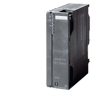
IM 153-1/153-2
- Заказные данные (8)
- Аксессуары (14)
- Информационные материалы
Информационные материалы
The ET 200M system with various interface modules is available for the distributed use of S7-300 I/O modules. Depending on the application purpose, the best suited IM in terms of costs and functions can be selected:
IM153-1 Standard
The IM153-1 is one reasonably priced variant that is excellently suited for most applications in the manufacturing environment. It permits the use of up to 8 S7-300 I/O modules.
IM153-2 High Feature
For higher requirements in manufacturing technology, such as the use of F-technology or the highest performance in conjunction with clock synchronization, the IM153-2 High Feature is available. This IM is also designed for use with the PCS7 in the field of process-oriented applications. This IM can be redundantly used and supports typical functions as they are required in the control field. These include, for example, clock synchronization or time stamping with an accuracy of up to 1ms.
Область применения
The IM 153-1 / IM 153-2 HF interface modules are required to connect the modular I/O device ET 200M to the PROFIBUS DP fieldbus.
These heads can be used in many different applications.
Special functions and modules for PCS7
The IM 153-2 is provided with special functions, such as clock synchronization, time stamping or I&M functions. In addition, special modules are available that take into account the increased diagnosis requirements in process engineering. For example, digital input modules allow for the connection of NAMUR sensors, have wire-break detectors at "0" and "1" signals and functions such as flatter monitoring or pulse stretching. In order to obtain a reasonable channel price, 8-channel HART modules may be used.
High availability systems
High availability systems are used in all cases where no system outage is permitted or the system restart after an unscheduled outage is tied to very high costs. Typical applications include, for example, power generation, power distribution, tunnel systems, baggage conveyor systems at airports, oil platforms, oil refineries, the manufacture of special glass, the semiconductor industry, etc.
In conjunction with the high-availability S7-400H (redundant CPUs), the ET 200M can be connected one-way (normal availability) or switched (increased availability).
Furthermore, the IM 153-2 can also be used in applications with S5-155H, with S7-300 / S7-400 with software redundancy as well as with the normal redundancy standardized in the PNO.
Area subject to explosion hazard
Various digital and analog modules exist as intrinsically safe versions for the Ex area. This means the modules themselves are installed in Zone 2 cost effectively; however, they can reach the sensors and actuators to be connected up to Zone 1. They are used, for example, in the chemical and pharmaceutical industry, on oil rigs or also in classic manufacturing plants, such as the printing industry or in paint shops in the automobile industry. They allow channel-wise, isolated processing of signals from the Ex zone 1. For use in the non-Ex area, the isolation from channel to channel for these modules is 250 V AC. In addition, there are still HART-capable analog modules.
Fail-safe systems
Fail-safe controllers switch to a safe state when a fault occurs and thus protect operators, machines, and the environment, e.g. for presses, robots or passenger transportation. For the connection of fail-safe signals to S7-300F or S7-400F/FH, several signal modules are available that provide SIL 2 or SIL 3 depending on the type of connection.
For the application of safety-related I/O modules, the IM 153-2 HF interface module must be used.
Highly dynamic production processes
Distributed solutions for the control of high-speed machines for production and machining processes with high accuracy are becoming increasingly important, e.g. for drive controls. For this reason, the time from the acquisition of a signal by the distributed I/O through to the appropriate response of the actuator must be kept as short and as accurately reproducible as possible. Synchronous coupling of a SIMATIC automation solution to the equidistant PROFIBUS is called "isochronous mode" and is supported by various signal modules of the ET 200M.
Дизайн
- The IM 153-1/153-2 interface module serves as the head module (IM; Interface Module) of the ET 200M. Up to 8 or 12 I/O modules from the module product range of the S7-300 automation system can be connected to the interface module.
- The interface module and the necessary I/O modules are assembled on a profile rail for the S7-300. During assembly, the I/O modules are connected to one another using bus connectors and using the IM 153 interface modules.
- For redundant operation, two IM 153-2 are mounted onto the BM IM/IM bus module. Special profile rails are available to accommodate the bus modules.
- When equipping the IM153 with S7-300 modules, slot rules do not have to be taken into account.
Функции
Features
IM 153-1 (Standard)
6ES7 153-1AA03-0XB0
IM153-2 High Feature
6ES7 153-2BA10-0XB0
6ES7 153-2BA70-0XB0
Mechanical data
Dimensions (W x H x D)
40 x 125 x 117 mm
40 x 125 x 117 mm
PROFIBUS-DP interface
Physics
RS 485 (copper)
RS 485 (copper)
PROFIBUS addresses
1 ... 125 (via DIP switch)
1 ... 125 (via DIP switch)
Baud rates
9.6 kBd ... 12 MBd
9.6 kBd ... 12 MBd
Autom. baud rate search
Yes
yes
SYNC / FREEZE capable
yes
yes
Specifications
Number of insertable modules
8
12
Number of E / A bytes (user data specifications)
128 / 128
244 / 244
Parameterized data
244
244
Diagnostics data
64
96
Module range
Digital IO
Unrestricted
unrestricted
Analog IO
unrestricted
unrestricted
FM
Restricted
(no K-bus module)unrestricted
CP
Restricted
Restricted
F modules
No
unrestricted
HART modules
no
unrestricted
IQ Sense
no
Unrestricted
Functionality
FW update
no
Yes (PROFIBUS)
I&M data1)
no
yes
Clock synchronization
no
yes
Module change during operation
Yes, with active backplane bus
yes, with active backplane bus
Clock synchronization
no
Yes
- Time stamping2)
yes
Accuracy class
no
10 ms / 1 ms
Number of signals/station
no
128
Redundancy
- System redundancy with S7-400H
no
Yes
- Software redundancy
no
Yes
- S5 redundancy with PLC155H
no
Yes
- Normal redundancy according to PNO3)
no
yes
Direct data exchange with F modules
no
yes
Forwards parameterized data from PG / PC ("C2 channel")
no
yes
Extended range of environmental conditions (outdoors)
no
Yes (only -2BA82-)
Configuration change in RUN 4)
- in the redundant system (H-CiR
no
Yes
- In the non-redundant system (Cir)
no
Yes
1) I&M data: Set-up and data access in accordance with the provisions in the PROFIBUS Guideline – Order No. 3.502, Version 1.1 of May 2003
2) Changes to digital inputs are tagged with a time stamp locally (in the IM 153 of the ET 200M) and transferred to the CPU by means of a process interrupt. If you want to achieve high-precision time stamping of 1ms with the IM153-2BAx2, a max. of 8 modules per IM can remain plugged in. Observe the installation and configuration guidelines in the ET 200M and PCS7 manual.
3) Normal redundancy according to PNO: "Flying Redundancy" according to PROFIBUS International Slave Redundancy Specification V1.2, Nov. 2004; Order No: 2.212
4) Changing the configuration in RUN means that changes to the hardware configuration, e.g. reparameterization or the addition of modules, can be performed during normal operation without any adverse effects.
How they work
The IM 153 interface module completely handles communication of the modular ET 200M I/O device with the host master device on the PROFIBUS DP.
The inputs and outputs are assigned to the respective master during configuration.
The IM 153-2 interface module allows the design of redundant PROFIBUS DP systems. On failure of the active branch, the passive IM 153-2 takes over the corresponding functions without interruption.
Parameterization
TIA Portal
The PROFIBUS modules are integrated in the TIA Portal (configurable as of Version V10.0, IM153-2BA10 as of Version V13.0.1).
STEP 7
Configuration is carried out using HW Config by selecting the respective headend from the corresponding HW catalog. The configuration with modules is also carried out from the corresponding HW catalog.
Third-party tools
Interfacing to third-party masters and configuration using third-party tools is carried out using the GSD file.
Технические данные
Order number
6ES7153-1AA03-0XB0
6ES7153-2BA10-0XB0
6ES7153-2BA70-0XB0
ET200M, INTERFACE MODULE IM153-1
ET200M, INTERFACE IM153-2 HF
ET200M, INTERFACE IM153-2 HF OUTDOOR
General information
Product type designation
IM 153-1 DP ST
IM 153-2 DP HF
Vendor identification (VendorID)
801Dh
801Eh
801Eh
Supply voltage
Rated value (DC)
24 V
24 V
● 24 V DC
Yes
Yes
Yes
permissible range (ripple included), lower limit (DC)
20.4 V
20.4 V
20.4 V
permissible range (ripple included), upper limit (DC)
28.8 V
28.8 V
28.8 V
external protection for power supply lines (recommendation)
not necessary
2,5 A
2,5 A
Mains buffering
● Mains/voltage failure stored energy time
5 ms
5 ms
5 ms
Input current
Current consumption, max.
350 mA; at 24 V DC
650 mA; with 24 V DC supply
650 mA
Inrush current, typ.
2.5 A
3 A
3 A
I²t
0.1 A²·s
0.1 A²·s
0.1 A²·s
Output voltage
Rated value (DC)
5 V
Output current
for backplane bus (5 V DC), max.
1 A
1.5 A
1.5 A
Power loss
Power loss, typ.
3 W
5.5 W
5.5 W
Address area
Addressing volume
● Inputs
128 byte
244 byte
244 byte
● Outputs
128 byte
244 byte
244 byte
Hardware configuration
Number of modules per DP slave interface, max.
8
12
12
Time stamping
Accuracy
1 ms; 1ms at up to 8 modules; 10ms at up to 12 modules
1 ms; 1ms at up to 8 modules; 10ms at up to 12 modules
Number of message buffers
15
15
Messages per message buffer
20
20
Number of stampable digital inputs, max.
128; Max. 128 signals/station; max. 32 signals/slot
128; Max. 128 signals/station; max. 32 signals/slot
Time format
RFC 1119
RFC 1119
Time resolution
0.466 ns
0.466 ns
Time interval for transmitting the message buffer if a message is present
1 000 ms
1 000 ms
Time stamp on signal change
rising / falling edge as signal entering or exiting
rising / falling edge as signal entering or exiting
Interfaces
Interface physics, RS 485
Yes
Yes
Yes
Interface physics, FOC
No
No
No
PROFIBUS DP
● Node addresses
1 to 125 permitted
1 to 125 permitted
1 to 125 permitted
● automatic detection of transmission rate
Yes
Yes
Yes
● Output current, max.
90 mA
70 mA
70 mA
● Transmission rate, max.
12 Mbit/s
12 Mbit/s
12 Mbit/s
● Transmission procedure
RS 485
RS 485
RS 485
● SYNC capability
Yes
Yes
Yes
● FREEZE capability
Yes
Yes
Yes
● Direct data exchange (slave-to-slave communication)
Yes; Sender
Yes; as publisher with all IO, as subscriber with F-IO only
Yes; as publisher with all IO, as subscriber with F-IO only
● Connector type
9-pin sub D socket
9-pin sub D
9-pin sub D
1. Interface
DP slave
● GSD file
(for DPV1) SIEM801D.GSD; SI01801D.GSG
SI05801E.GSG
SI05801E.GSG
● automatic baud rate search
Yes
Yes
Yes
Protocols
Bus protocol/transmission protocol
PROFIBUS DP to EN 50170
PROFIBUS DP to EN 50170
PROFIBUS DP to EN 50170
Isolation
Isolation tested with
Isolation voltage 500 V
Isolation voltage 500 V
Isolation voltage 500 V
Degree and class of protection
Degree of protection acc. to EN 60529
● IP20
Yes
Yes
Yes
Ambient conditions
Ambient temperature during operation
● min.
0 °C
0 °C
● max.
60 °C
60 °C
Air pressure acc. to IEC 60068-2-13
● Installation altitude above sea level, max.
3 000 m
3 000 m
3 000 m
Configuration
Configuration software
● STEP 7
STEP 7 / COM PROFIBUS / non-Siemens tools via GSD file
Yes; STEP 7 / COM PROFIBUS / non-Siemens tools via GSD file
Yes; STEP 7 / COM PROFIBUS / non-Siemens tools via GSD file
Dimensions
Width
40 mm
40 mm
40 mm
Height
125 mm
125 mm
125 mm
Depth
117 mm
117 mm
117 mm
Weights
Weight, approx.
360 g
360 g
360 g
Order number
6ES7195-7HD10-0XA0
ET200M, BUS UNIT F. 2 IM 153-2 RED.
Accessories
belongs to product
ET 200M
Dimensions
Width
97 mm
Height
92 mm
Depth
30 mm
Weights
Weight, approx.
133 g
Order number
6ES7195-7HA00-0XA0
6ES7195-7HB00-0XA0
6ES7195-7HC00-0XA0
ET200M, BUS UNIT F. PS AND IM 153
ET200M, BUS UNIT F. 2 40MM I/O MODULES
ET200M, BUS UNIT F. 1 80MM I/O MODULE
Accessories
belongs to product
ET 200M
ET 200M
ET 200M
Dimensions
Width
97 mm
97 mm; 80 mm when installed
97 mm; 80 mm when installed
Height
92 mm
92 mm
92 mm
Depth
30 mm
30 mm
30 mm
Weights
Weight, approx.
111 g
140 g
127 g
Дальнейшая информация
Brochures
Information material for downloading can be found in the Internet:
http://www.siemens.com/simatic/printmaterial