
- Каталог оборудования Siemens
- Каталог продуктов Siemens Industry
- Приводная техника
- Техника автоматизации
- Системы автоматизации
- Системы визуализации SIMATIC HMI
- Системы идентификации
- Промышленные коммуникации SIMATIC NET
- Промышленные аппараты управления SIRIUS
- Системы
- Коммутационные аппараты SIRIUS
- Аппаратура защиты
- Фидеры и пускатели двигателей
- Функциональные, коммутирующие реле и преобразователи
- Сиcтема обслуживания двигателей
- Логические модули LOGO!
- Реле контроля SIRIUS 3RR, 3UG для электрических и неэлектрических величин.
- Электронное реле времени
- Monitoring relays
- Реле контроля SIRIUS 3RR2 для установки на контакторы 3RT2
- Реле контроля тока SIRIUS 3RR24 с IO-Link
- Реле контроля электрических величин
- Реле контроля SIRIUS 3UG48 для отдельной установки (с возможностью коммуникации по IO-Link)
- Реле контроля температуры
- Реле контроля температуры SIRIUS 3RS14, 3RS15 с возможностью коммуникации по IO-LinkРеле для одного датчика (с цифровым параметрированием)Реле для 3-х датчиков (с цифровым параметрированием)Принадлежности
- Реле контроля температуры SIRIUS 3RS14, 3RS15 с возможностью коммуникации по IO-Link
- SIRIUS 3RN2 thermistor motor protection
- Для холодно-паянных температурных датчиков
- Термисторная защита двигателей
- Согласующие реле и преобразователи сигналов
- Оборудование безопасности
- Позиционные выключатели и выключатели для систем безопасности
- Устройства управления и индикации
- Планирование и конфигурирование для SIRIUS
- Блоки питания SITOP
- Блоки питания SIRIUS 4AV
- Transformers
- Фильтры SIDAC-F
- Дроссели SIDAC-D
- Промышленные информационные технологии
- Управление на базе РС
- Системы управления процессом
- Контрольно-измерительные приборы
- Анализаторы процесса
- Блоки питания SITOP
- Продукты для специальных требований
- Energy
- Автоматизация и безопасность зданий
- Низковольтная коммутационная техника
- Технология безопасности
- Системные решения и продукты для отраслей
- Сервис
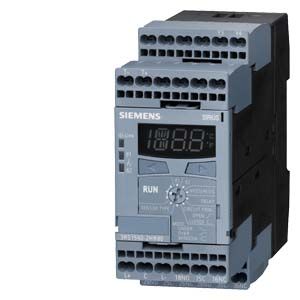
Реле контроля температуры SIRIUS 3RS14, 3RS15 с возможностью коммуникации по IO-Link
- Информационные материалы
Информационные материалы
Реле контроля температуры SIRIUS 3RS10/3RS11 могут применяться для измерения температуры в твердых, жидких и газообразных средах. Температура измеряется датчиком в среде и обрабатывается реле, которое контролирует превышение верхней или нижней границы рабочего диапазона, а также уставки в пределах заданного диапазона (функция окна).
Кроме предупреждения и срабатывания приборы могут использоваться и как одно-, двух- и трехточечные термоконтроллеры
- 3RS14: для резистивных датчиков
- 3RS15: для термоэлементов
Функция
Реле
3RS14 40
3RS14 41
3RS15 40
Тип датчика
Количество датчиков
1
3
1
Резистивный датчик
x
--
x
Термоэлемент
--
--
x
Контроль температуры
Превышение
x
x
x
Понижение
x
x
x
Количество настраиваемых пределов
2
2
2
x поддерживается
-- не поддерживается

Обычное реле температуры
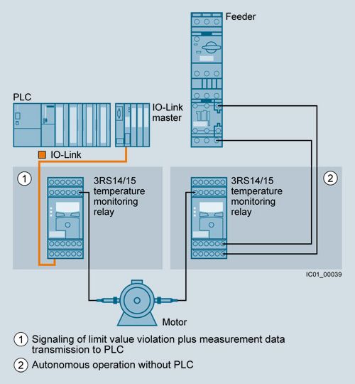
Реле температуры с IO-Link
Примечания:
Устройства с коммуникацией по IO-Link:
- Любой контроллер с поддержкой IO-Link (напр. ET200S с CPU или S7-300 с ET200S9 распределенной периферией)
- IO-Link мастер (IO-Link мастер 4SI IO-Link или модуль интерфейса 4SI SIRIUS , соединяющий приборы SIRIUS IO-Link с контроллером)
Каждое реле требует IO-Link канала.
Схема заказного номера
Разряд заказного No.
1. - 3.
❒❒❒4.
❒5.
❒6.
❒7.
❒
–8.
❒9.
❒10.
❒11.
❒12.
❒Реле контроля t
3RS
Тип прибора
❒
❒
Тип датчика
❒
❒
Тип присоединения
❒
Кол-во и тип выходов
❒
Напряжение питания
❒
Диапазон измерения
❒
Особые модификации
❒
Пример
3RS
1
4
4
0
–
1
H
B
5
0
Примечание:
Схема заказного номера приведена только для лучшего понимания логики образования номеров
Особенности
Преимущества от энергоэффективности

Процесс энергоменеджмента
Новые промышленные аппараты SIRIUS могут внести основной вклад в энергоэффективность предприятия (http://webservices.siemens.com/medaps/webeditor/www.siemens.de/sirius/energiesparen).
Реле контроля температуры 3RS14 и 3RS15 на IO-Link вносят следующий вклад:
- Контроль обогрева и вентиляции технологических процессов и пространства шкафов управления
Технические данные
More information
For technical specifications, see https://support.industry.siemens.com/cs/ww/en/ps/16370/td
For FAQs, see https://support.industry.siemens.com/cs/ww/en/ps/16370/faq
For the manual and circuit diagrams, see https://support.industry.siemens.com/cs/ww/en/view/54375463
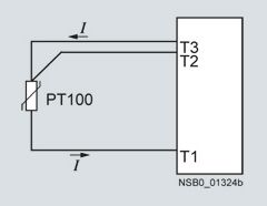
Connection for resistance sensors
Two-wire measurement
When two-wire temperature sensors are used, the resistances of the sensor and wiring are added. The resulting systematic error must be taken into account when the signal evaluation unit is calibrated. A jumper must be connected between terminals T2 and T3 for this purpose.

Wiring errors
The errors that are generated by the wiring comprise approximately 2.5 K/Ω. If the resistance of the cable is not known and cannot be measured, the wiring errors can also be estimated using the following table.
Temperature drift dependent on the length and cross-section of the cable with PT100 sensors and an ambient temperature of 20 °C, in K:
Cable length in m
Cross-section mm²
0.5
0.75
1
1.5
Temperature drift in K:
0
0
0
0
0
10
1.8
1.2
0.9
0.6
25
4.5
3.0
2.3
1.5
50
9.0
6.0
4.5
3.0
75
13.6
9.0
6.8
4.5
100
18.1
12.1
9.0
6.0
200
36.3
24.2
18.1
12.1
500
91.6
60.8
45.5
30.2
Example: on a PT100 sensor with a cable length of 10 m and a conductor cross-section of 1 mm2 the temperature drift equals 0.9 K.
Three-wire measurement
To minimize the effects of the line resistances, a three-wire circuit is often used. Using the additional cable, two measuring circuits can be formed of which one is used as a reference. The signal evaluation unit can then automatically calculate the line resistance and take it into account.
Connection of thermocouples
Based on the thermo-electrical effect, a differential temperature measurement will be performed between the measuring point and the signal evaluation unit.
This principle assumes that the signal evaluation unit knows the temperature at the clamping point (T2). For this reason, the 3RS15 temperature monitoring relay has an integral compensator that determines this comparison temperature and builds it into the result of the measurement. The thermal sensors and cables must therefore be insulated.
The absolute temperature is therefore calculated from the ambient temperature of the signal evaluation unit and the temperature difference measured by the thermocouple. Temperature detection is therefore possible (T1) without needing to know the precise ambient temperature of the clamping point at the signal evaluation unit (T2).
The connecting cable is only permitted to be extended using connecting leads that are made from the same material as the thermocouple. If a different type of conductor is used, an error will result in the measurement.

For more information, see http://www.ephy-mess.de/en/welcome/
Operating principle
When the temperature reaches the set limit value ϑ1, the output relay K1 changes its switching state once the set time t has elapsed. The delay time can be adjusted. K2 responds in the same manner to the lower threshold ϑ2.
The output relays return immediately to their original state (the RESET response is configured at Auto RESET) once the temperature reaches the respective hysteresis value.
Both thresholds ϑ1 and ϑ2 can be parameterized for overshooting or undershooting. This makes it possible to use a limit value for issuing an alarm signal to announce that a limit value is about to be overshot or undershot. The other limit value can be used for disconnection or to implement two-point or three-point control.
Note:
The "Temperature monitoring mode" parameter can be used to set the desired monitoring type (monitoring for overshooting or undershooting or range monitoring).
With the closed-circuit principle selected
Temperature overshoot

Temperature undershoot

Range monitoring

Memory function
The digitally adjustable temperature monitoring relays for IO-Link have a memory function. The memory function is illustrated below by the example of a temperature overshoot.
When the temperature reaches the set limit value ϑ1, the output relay K1 changes its switching state once the set time t has elapsed (output relay K2 responds to ϑ2 in the same way).
The temperature monitoring relays for IO-Link respond as described below:
- With temperature monitoring relays for IO-Link the memory function is activated as standard (RESET). The output relays only return to the original state when the temperature falls below the set hysteresis value and when one of the following steps is performed:
- Brief jumpering of the Y3/Y4 terminals
- Set the rotary knob to "RUN" position and press the right-hand arrow key
- Perform a RESET through IO-Link
- If the Y3/Y4 terminals are permanently jumpered, the memory function is deactivated (Auto RESET). The output relays return immediately to their original state once a previously occurred fault has been rectified and the temperature falls below the respective hysteresis value.
With the closed-circuit principle selected

Characteristic curves
For resistance sensors

Short-circuit and open-circuit detection as well as the measuring range are limited, depending on the sensor type.
Measuring ranges for resistance sensors
Sensor type
Short circuit
Open circuit
3RS1040/3RS1041
Measuring range in °C3RS1042
Measuring range in °CPT100
✓
✓
–50 ... +750
–58 ... +1382
PT1000
✓
✓
–50 ... +500
–58 ... +932
KTY83-110
✓
✓
–50 ... +175
–58 ... +347
KTY84
✓
✓
–40 ... +300
–40 ... +572
NTC1)
✓
--
+80 ... +160
+176 ... +320
✓ Detection possible
-- Detection not possible1) NTC type: B57227-K333-A1 (100 °C: 1.8 kΩ; 25 °C: 32.762 kΩ).
For thermocouples

Characteristic curves for sensor types K, N, J, E and T

Characteristic curves for sensor types S, R and B
Measuring ranges for thermocouples
Sensor type
Short circuit
Open circuit
3RS1040/3RS1041
Measuring range in °C3RS1042
Measuring range in °CK
--
✓
–99 ... +1350
–146.2 ... +2462
N
--
✓
–99 ... +1300
–146.2 ... +2372
J
--
✓
–99 ... +1200
–146.2 ... +2192
E
--
✓
–99 ... +999
–146.2 ... +1830.2
T
--
✓
–99 ... +400
–146.2 ... +752
S
--
✓
0 ... +1750
32 ... +3182
R
--
✓
0 ... +1750
32 ... +3182
B
--
✓
400 ... +1800
+752 ... +3272
✓ Detection possible
-- Detection not possible
Дальнейшая информация
Инструкция "3RS14/3RS15 temperature monitoring relays for IO-Link"
http://support.automation.siemens.com/WW/view/en/54375463.
Примечание по безопасности
Для безпасной эксплуатации установки должны быть приняты соответствующие защитные меры (включая безпасность IT, например, сегментированием цепи).
Для получения дальнейшей информации по промышленной безопасности, пройдите по ссылке:
http://www.siemens.com/industrialsecurity.