
- Каталог оборудования Siemens
- Каталог продуктов Siemens Industry
- Приводная техника
- Преобразователи
- Стандартные преобразователи
- Общая информация о базовых преобразователях SINAMICS V
- Преобразователи частоты общего назначения SINAMICS G
- Высокопроизводительные преобразователи SINAMICS S
- MICROMASTER
- SIPLUS POSMO A
- SIMODRIVE POSMO
- LOHER DYNAVERT Drive System
- Преобразователи на среднее напряжение
- Преобразователи постоянного тока
- Стандартные преобразователи
- Двигатели переменного тока
- Generators
- Мотор-редукторы
- Flender Gear Units
- Couplings
- Инструментальное программное обеспечение
- Дополнительные компоненты
- Преобразователи
- Техника автоматизации
- Energy
- Автоматизация и безопасность зданий
- Низковольтная коммутационная техника
- Технология безопасности
- Системные решения и продукты для отраслей
- Сервис
- Приводная техника
CU310-2 Control Unit
- Заказные данные (2)
- Аксессуары (12)
- Информационные материалы
Информационные материалы

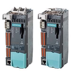
CU310-2 PN and CU310-2 DP Control Units
The CU310‑2 Control Unit for the communication and open-loop/closed-loop control functions of a Power Module is combined with the Power Module to create a powerful single drive. A PROFINET (PN) variant and a PROFIBUS (DP) variant are available for fieldbus communication.
Дизайн
CU310‑2 Control Units feature the following interfaces as standard:
- Fieldbus interface
- CU310‑2 PN:
1 PROFINET interface with 2 ports (RJ45 sockets) with PROFIdrive V4 profile - CU310‑2 DP:
1 PROFIBUS interface with PROFIdrive V4 profile
- CU310‑2 PN:
- 1 DRIVE‑CLiQ socket to allow communication with other DRIVE‑CLiQ nodes
- 1 encoder evaluation for evaluating the following encoder signals
- Incremental encoder TTL/HTL
- SSI encoders without incremental signals
- 6 parameterizable digital inputs (isolated) or alternatively
3 parameterizable, fail-safe digital inputs (isolated, can be used with firmware V4.5 and higher).
The fail-safe digital inputs can be routed, i.e. they can be routed via PROFIsafe to a higher-level controller. - 1 digital output (isolated) or alternatively
1 parameterizable, fail-safe digital output (isolated, can be used with firmware V4.5 or higher) - 5 parameterizable digital inputs (floating)
- 8 parameterizable bidirectional digital inputs/digital outputs (non-floating)
- 1 analog input, either ± 10 V (resolution 12 bits + sign) or ± 20 mA (11 bits + sign)
- 1 Ethernet interface (RJ45 socket) for commissioning and diagnostics
- 1 serial RS232 interface
- 1 connection for the electronics power supply via the 24 V DC supply connector
- 1 temperature sensor input (KTY84‑130 or PTC)
- 3 measuring sockets and one reference ground for commissioning support
- 1 slot for the CompactFlash card on which firmware and parameters are stored
- 1 PM-IF interface for communication with Power Modules in blocksize format
- 1 interface to the BOP20 Basic Operator Panel
- 1 PE connection
The status of the CU310-2 Control Unit is indicated via multi-color LEDs.
A BOP20 Basic Operator Panel can also be snapped directly onto the CU310‑2 Control Unit for diagnostic procedures.
As the firmware and parameter settings are stored on a plug-in CompactFlash card, the Control Unit can be changed without the need for software tools.
Интеграция
Power Modules in chassis format are controlled from the CU310-2 Control Unit via the DRIVE-CLiQ interface. Sensor Modules and Terminal Modules must be connected to the free DRIVE‑CLiQ sockets of the Power Module.
Parameter settings can be changed directly via the BOP20 Basic Operator Panel. The BOP20 Basic Operator Panel can also be snapped onto the CU310‑2 Control Unit during operation to perform diagnostics.
The CU310‑2 Control Unit and other connected components are commissioned and diagnosed with the STARTER commissioning tool.
A CU310-2 DP Control Unit communicates with the higher-level control system using PROFIBUS and the PROFIdrive V4 profile.
A CU310‑2 PN Control Unit communicates with the higher-level control system using PROFINET IO and the PROFIdrive V4 profile.
The SINAMICS S120 drive system with the CU310‑2 PN Control Unit then assumes the function of a PROFINET IO device and can perform the following functions:
- PROFINET IO device
- 100 Mbit/s full duplex
- Supports real-time classes of PROFINET IO:
- RT (Real-Time)
- IRT (Isochronous Real-Time), minimum send cycle 500 μs
- Connects to controls as PROFINET IO devices using PROFIdrive compliant with Specification V4
- Standard TCP/IP communication for engineering processes using the STARTER commissioning tool
- Integrated 2-port switch with two RJ45 sockets based on the ERTEC ASIC. The optimum topology (line, star, tree) can therefore be configured without additional external switches.
A 24 V supply voltage must be connected to terminal X124 for the digital outputs to be used. The CU310-2 DP Control Unit requires a CompactFlash card with firmware V4.5 or higher.

Connection example of CU310-2 Control Unit
Технические данные
CU310‑2 Control Unit
PROFINET: 6SL3040-1LA01-0AA0
PROFIBUS: 6SL3040-1LA00-0AA0
Power requirement, max.
At 24 V DC,
without taking into account the digital outputs and DRIVE‑CLiQ supply0.35 A for CU310-2 Control Unit + 0.5 A for Power Module
Conductor cross-section, max.
2.5 mm2
Fuse protection, max.
20 A
Digital inputs
in accordance with IEC 61131‑2 Type 1
5 floating digital inputs
8 bidirectional non-floating digital inputs/outputs
3 parameterizable, fail-safe digital inputs (isolated) or alternatively 6 parameterizable digital inputs (isolated)
- Voltage
-3 ... +30 V
- Low level (an open digital input is interpreted as "low")
-3 ... +5 V
- High level
15 ... 30 V
- Current consumption at 24 V DC, typ.
10 mA
- Delay time of digital inputs 1), approx.
- L → H
50 μs
- H → L
100 μs
- Delay time of high-speed digital inputs 1), approx.
(high-speed digital inputs can be used for position detection)
- L → H
5 μs
- H → L
50 μs
- Conductor cross-section, max.
1.5 mm2
Digital outputs
continuously short-circuit proof
8 bidirectional non-floating digital inputs/outputs
- Voltage
24 V DC
- Load current per digital output 2), max.
500 mA
- Delay time 1), typ./max.
- L → H
150 μs/400 μs
- H → L
75 μs/100 μs
- Conductor cross-section, max.
1.5 mm2
Analog input
1 analog input for current or voltage input, switchable
- Voltage
-10 ... +10 V; Ri > 100 Ω
- Current
-20 ... +20 mA; Ri > 250 Ω
- Max. range that can be resolved
-11 ... +11 V
- Common mode range
±12 V
- Resolution
13 bits (with respect to the maximum range that can be resolved)
Encoder evaluation
- Incremental encoder TTL/HTL
- SSI encoders without incremental signals
- Input impedance
- TTL
570 Ω
- HTL, max.
16 mA
- Encoder supply
24 V DC / 0.35 A or
5 V DC / 0.35 A- Encoder frequency, max.
300 kHz
- SSI baud rate
100 ... 250 kBaud
- Resolution absolute position SSI
30 bits
- Cable length, max.
- TTL encoder
100 m
(only bipolar signals permitted) 3)
- HTL encoder
100 m for unipolar signals
300 m for bipolar signals 3)
- SSI encoder
100 m
Power loss
<20 W
PE connection
M5 screw
Dimensions
- Width
73 mm
- Height
- CU310-2 PN
191 mm
- CU310-2 DP
187 mm
- Depth
75 mm
Weight, approx.
0.95 kg
1) The specified delay times refer to the hardware. The actual reaction time depends on the time slice in which the digital input or output is processed.
2) In order to use the digital outputs, an external 24 V power supply must be connected to terminal X124.
3) Signal cables twisted in pairs and shielded.
- Fieldbus interface