
- Каталог оборудования Siemens
- Каталог продуктов Siemens Industry
- Приводная техника
- Преобразователи
- Стандартные преобразователи
- Общая информация о базовых преобразователях SINAMICS V
- Преобразователи частоты общего назначения SINAMICS G
- Преобразователи частоты SINAMICS G110
- Компактные преобразователи SINAMICS G120C
- Преобразователи для насосов, вентиляторов,компрессоров SINAMICS G120P
- Обзор
- Введение
- Преобразователи для насосов, вентиляторов, компрессоров SINAMICS G120P
- Integrated Drive Systems
- SINAMICS G120P, built-in and wall-mounted units, IP20/IP54/IP55
- SINAMICS G120P Cabinet, cabinet units, IP20 to IP54
- Selection and engineering tools
- Инженерные инструменты
- Services and documentation
- Инструменты проектирования
- Сервис и документация
- Стандартные преобразователи SINAMICS G120
- SINAMICS G110M distributed inverters
- Преобразователь частоты SINAMICS G110D для распределенной периферии
- Преобразователи частоты SINAMICS G120D
- Преобразователи SINAMICS G130 формат шасси
- Преобразователь частоты SINAMICS G150 шкафного исполнения
- SINAMICS G180
- Высокопроизводительные преобразователи SINAMICS S
- MICROMASTER
- SIPLUS POSMO A
- SIMODRIVE POSMO
- LOHER DYNAVERT Drive System
- Преобразователи на среднее напряжение
- Преобразователи постоянного тока
- Стандартные преобразователи
- Двигатели переменного тока
- Generators
- Мотор-редукторы
- Flender Gear Units
- Couplings
- Инструментальное программное обеспечение
- Дополнительные компоненты
- Преобразователи
- Техника автоматизации
- Energy
- Автоматизация и безопасность зданий
- Низковольтная коммутационная техника
- Технология безопасности
- Системные решения и продукты для отраслей
- Сервис
- Приводная техника
SINAMICS G120P Cabinet, 110 kW to 630 kW
- Заказные данные (30)
- Информационные материалы
Информационные материалы

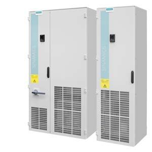
SINAMICS G120P Cabinet drive inverter cabinet units, versions A and C
With its SINAMICS G120P Cabinet drive inverter cabinet units, Siemens is offering a cost-effective drive system on which all line-side and motor-side components as well as the Power Module are integrated into a ready-to-use standardized cabinet system.
A wide range of catalog options are available for the implementation of customer-specific configurations, which are complemented and type tested in the overall system. Special requests can be implemented on request on account of the flexible production process.
The SINAMICS G120P Cabinet is especially suitable for pumps, fans, and compressor applications on account of the special functions included in the standard version, such as pump cascading, multi-zone control, emergency mode, etc.
With its high-performance, sensorless vector control, the very ruggedly designed inverter covers a wide range of applications – even in harsh industrial environments. Simple, clear engineering supports assist the correct selection of components, and thus form the basis for safe, long-term operation.
Commissioning with the Intelligent Operator Panel (IOP) integrated in the control cabinet door can be performed quickly and easily. A commissioning wizard guides the user conveniently through all the essential commissioning parameters.
There are two versions of the drive inverter cabinet units:
- Version A (110 kW to 630 kW - 148 to 845 hp)
enables all optionally available line connection components, such as the main switch, main contactor, line fuses, line filter, motor-side components and additional monitoring devices to be installed - Version C (110 kW to 400 kW - 148 to 536 hp)
space-saving design with line reactor and optional main switch. This particularly slimline design can be used, for example, when line connection components are accommodated in a central low-voltage distribution panel (MCC) in the customer's plant or system.
SINAMICS G120P Cabinet drive inverter cabinet units are available for the following voltages and outputs:
Line voltage
Power range
380 ... 480 V 3 AC
110 ... 560 kW (148 ... 751 hp)
500 ... 690 V 3 AC
500 ... 630 kW (671 ... 845 hp)
The units have degree of protection IP20 as standard. They are optionally available with degrees of protection IP21, IP23, IP43 and IP54.
Область применения
Variable-speed drives are ideal for all applications that involve moving, conveying, pumping, or compressing liquids or gases.
This means the following applications in particular:
- Pumps
- Fans
- Compressors
Дизайн
SINAMICS G120P Cabinet drive inverter cabinet units are characterized by their modular and service-friendly design.
A wide range of options is available depending on the cabinet version, which permits optimum adaptation of the drive system to the respective requirements (see section Options).
Example of design of a SINAMICS G120P Cabinet drive inverter cabinet unit, version A with a CU230P-2 Control Unit

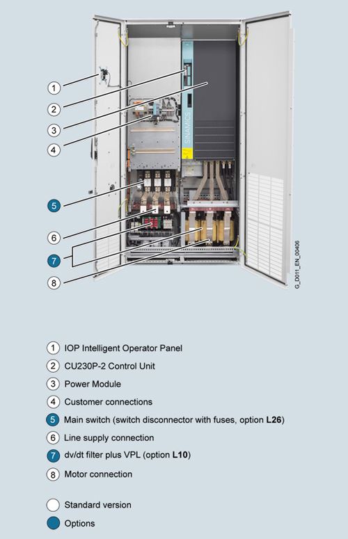
Basic design of a SINAMICS G120P Cabinet drive inverter cabinet unit with several significant options
Coated modules
The following inverter components are equipped as standard with coated modules:
- Power Modules
- Control Units
- Intelligent Operator Panel IOP
The coating on the modules protects the sensitive SMD components against corrosive gases, chemically active dust and moisture.
Nickel-plated busbars
All of the busbars used in the inverter cabinet are nickel-plated in order to achieve the best possible immunity to environmental effects. Further, the bare copper connections do not have to be cleaned for customer connections.
Note:
For some options, for technical reasons, parts of the copper busbars cannot be nickel-plated.
EMC shielding busbars and PE busbars
The Cabinet Modules are delivered with a EMC shielding busbar and a PE busbar as standard. The EMC shielding busbar is used to connect shielded power cables for line and motor supply cables. The PE busbar is used to connect and secure PE cables.
Crane transport aids
The inverter cabinet units are supplied with a crane transport aid mounted on the top. In the case of single cabinets up to a width of 1200 mm (47.2 in), transport eyebolts are provided to transport the unit by crane. Transport rails are used with cabinet widths >1200 mm (47.2 in) or for several cabinets (e.g. option L01). Rope spreaders should be used for low crane hook heights.
Degrees of protection of cabinet units
The EN 60529 standard covers the protection of electrical equipment by means of housings, covers or equivalent, and includes:
- Protection of persons against accidental contact with live or moving parts within the housing and protection of the equipment against the ingress of solid foreign matter (touch protection and protection against ingress of solid foreign bodies)
- Protection of the equipment against the ingress of water (water protection)
- Abbreviations for the internationally agreed degrees of protection
The degrees of protection are specified by abbreviations comprising the code letters IP and two digits.
Degrees of protection of the drive inverter cabinet unit
First digit
(touch protection and protection against ingress of foreign solid matter)Second digit
(protection of the equipment against the ingress of water)IP20 (standard)
Protected against solid foreign bodies with a diameter ≥ 12.5 mm.
No water protection
IP21 (option M21)
Protected against solid foreign bodies with a diameter ≥ 12.5 mm.
Protected against drip water
Vertically falling drip water shall not have a harmful effect.
IP23 (option M23)
Protected against solid foreign bodies with a diameter ≥ 12.5 mm.
Protected against spray water
Water sprayed on both sides of the vertical at an angle of up to 60° shall not have a harmful effect.
IP43 (option M43)
Protected against solid foreign bodies with a diameter ≥ 1 mm.
Protected against spray water
Water sprayed on both sides of the vertical at an angle of up to 60° shall not have a harmful effect.
IP54 (option M54)
Dust protected.
Ingress of dust is not totally prevented, but dust must not be allowed to enter in such quantities that the functioning or safety of the equipment is impaired.
Protected against splash water
Water splashing onto the enclosure from any direction shall not have a harmful effect.
Характеристика
Derating data
SINAMICS G120P Cabinet units and the associated system components are rated for an ambient temperature of 40 °C and installation altitudes up to 1000 m above sea level.
At ambient temperatures of > 40 °C, the output current must be reduced. Ambient temperatures above 50 °C are not permissible.
At installation altitudes > 1000 m above sea level, it must be taken into account that the air pressure, and therefore air density, decreases as the height increases. As a consequence, the cooling efficiency and the insulation capacity of the air also decrease.
Due to the reduced cooling efficiency, it is necessary, on the one hand, to reduce the ambient temperature, and on the other hand, to lower heat loss in the inverter cabinet unit by reducing the output current.
As additional measure for installation altitudes from 2000 m up to 4000 m, an isolating transformer is required in order to reduce transient overvoltages according to EN 60664‑1.
Automatic adjustment of pulse frequency
In the factory setting, the drive starts with a pulse frequency of 4 kHz and reduces the pulse frequency automatically to the associated required frequencies when loaded. When the load decreases, the pulse frequency is increased automatically up to 4 kHz. The values of the rated current apply to a pulse frequency of 2 kHz and an ambient temperature of 40 °C and are reached at any time by the automatic adaptation of the output pulse frequency.
Current derating as a function of installation altitude

Permissible output current as a function of the installation altitude for SINAMICS G120P Cabinet units, frame size GX

Permissible output current as a function of the installation altitude for SINAMICS G120P Cabinet units, frame sizes HX and JX
Note:
The connected motors and power elements must be considered separately.
Current derating as a function of ambient temperature

Permissible output current as a function of the ambient temperature
Current derating as a function of the line voltage
The SINAMICS G120P Cabinet inverter cabinet units supply a constant power over the full permissible range of line voltage.
The constant power results in current derating as a function of the line voltage.
SINAMICS G120P Cabinet
Rated output current Irated at 380/400 V
380 V
400 V
415 V
460 V
480 V
Type
A
%
%
%
%
%
6SL3710-1PE32-1 . A0-Z
205
100
100
95.9
83.5
78
6SL3710-1PE32-5 . A0-Z
245
100
100
95.3
83.1
75
6SL3710-1PE33-0 . A0-Z
300
100
100
96.6
86.2
81.6
6SL3710-1PE33-7 . A0-Z
370
100
100
96.9
87.8
83.7
6SL3710-1PE34-6 . A0-Z
460
100
100
96.4
85.4
80.6
6SL3710-1PE35-8 . A0-Z
585
100
100
96.9
87.8
83.7
6SL3710-1PE36-6 . A0-Z
655
100
100
96.4
85.4
80.6
6SL3710-1PE37-4 . A0-Z
735
100
100
96.6
86.6
82.1
6SL3710-1PE38-4AA0-Z
840
100
100
96.4
85.4
80.6
6SL3710-1PE38-8AA0-Z
910
100
100
96.4
85.8
81.2
6SL3710-1PE41-0AA0-Z
1021
100
100
96.8
87.3
83
SINAMICS G120P Cabinet
Rated output current Irated at 500 V/690 V
500 V
575 V
600 V
660 V
690 V
Type
A
%
%
%
%
%
6SL3710-1PG35-8AA0-Z
581/535
100
96.9
95.4
93.3
92.1
6SL3710-1PG36-5AA0-Z
654/595
100
96.5
95.3
92.4
91.0
6SL3710-1PG37-2AA0-Z
725/665
100
96.7
95.6
93.0
91.7
Operating ranges
An additional dimensioning aid is available for all inverters with a PM330 Power Module. The purpose of this aid is to ensure the constant reliable operation of the inverter, in particular with regard to service life expectancy.
The dimensioning aid clearly distinguishes between continuous operating ranges and short-time operating ranges. As a result, due consideration can be given to operating ranges when the plant is configured. For further details, please refer to the diagram below and the explanatory text.

Continuous operation (green area) permissible.
Short-time operation (yellow area) permissible for 2 % of the total operating period without significant reduction in the inverter service life; no overload reaction triggered by the thermal monitoring model.
Sporadic short-time operation (red area) permissible for only very short, rare operating states lasting less than 0.1 % of the total operating period without significant reduction in the inverter service life; no overload reaction triggered by the thermal monitoring model on condition of compliance with the duty times specified in the diagram.
Overload capability
SINAMICS G120P Cabinet drive inverter cabinet units are equipped with an overload reserve to deal with breakaway torques, for example. If larger surge loads occur, this must be taken into account when configuring. In drives with overload requirements, the appropriate base-load current must, therefore, be used as a basis for the required load.
The unit can operate in two different duty cycles in the permissible continuous operating range shown in the diagram (green area). Depending on how the system is dimensioned, the relevant base-load current is effective as a rated quantity.
The criterion for overload is that the drive is operated with its base-load current before and after the overload occurs on the basis of a duty cycle duration of 300 s.
The base-load current for a low overload IL is the basis for a duty cycle of 110 % for 60 s or 135 % for 3 s.
The base-load current IH for a high overload is based on a duty cycle of 150 % for 60 s.

Overload capability, low overload

Overload capability, high overload
Функции
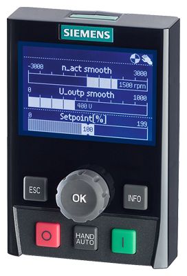
Intelligent Operator Panel IOP
The IOP (Intelligent Operator Panel) is mounted in the door of the cabinet units. It is used to operate and commission the drive system. The IOP is an extremely user-friendly, powerful operator panel.
The IOP supports both entry-level personnel and drive experts. Thanks to the large plain text display, the menu prompting and the application wizards, it is easy to perform commissioning. A drive can be essentially commissioned without having to use a printed parameter list – as the parameters are displayed in plain text, and explanatory help texts and the parameter filtering function are provided.
Application wizards interactively guide you when commissioning important applications such as pumps and fans. There is a basic commissioning wizard for general commissioning.
The drives are easily controlled manually using directly assigned buttons and the navigation wheel. The IOP has a dedicated switchover button to switch from automatic to manual mode.
The inverter can be diagnosed in a user-friendly fashion using the plain text display of faults and alarms. Help texts can be obtained by pressing the INFO button. Up to two process values can be graphically visualized and up to four process values can be numerically visualized on the status screen/display. Process values can also be displayed in technological units.
The IOP supports standard commissioning of identical drives. For this purpose, a parameter list can be copied from an inverter into the IOP and downloaded into other drive units of the same type as required. This functionality is available only if a memory card is installed in the Control Unit.
The IOP supports the following languages 1): German, English, French, Italian, Spanish, Portuguese, Dutch, Swedish, Russian, Czech, Polish, Turkish, Finnish.
If option D91 is selected, in the factory, an IOP containing the Chinese, English and German languages is integrated into the cabinet door of the inverter.
The operating temperature of the IOP is 0 to 50 °C (32 to 122 °F).
1) Further information is available at
https://support.industry.siemens.com/cs/document/67273266Communication with higher-level control and customer terminal block
Depending on the selected CU230P‑2 Control Unit, the following interfaces for communication with the higher-level control system are provided:
- PROFINET, EtherNet/IP (option K96)
- PROFIBUS (option K97)
- USS/Modbus RTU/BACnet MS/TP, FLN P1 protocol (option K98)
The Control Unit can be connected to the higher-level control via its digital inputs and outputs.
Open-loop and closed-loop control functions
The inverter control contains a high-quality, sensorless vector control with speed and current controls as well as motor and inverter protection.
Software and protective functions
The software functions available as standard are described below:
Software and protective functions
Description
Setpoint input
The setpoint can be input both internally and externally. It is applied internally as a fixed setpoint, motorized potentiometer setpoint or jog setpoint and externally via the communications interface or an analog input on the customer terminal block. The internal fixed setpoint and the motorized potentiometer setpoint can be switched over or adjusted using control commands from any interface.
Motor identification
The automatic motor identification function makes commissioning faster and easier and optimizes closed-loop control of the drive.
Ramp-function generator
An advanced ramp-function generator with separately adjustable ramping times, together with adjustable rounding times in the lower and upper speed ranges, allows the drive to be smoothly accelerated and braked. As a consequence, this avoids the drive train from being overloaded and reduces the stress on mechanical components. The down ramps can be parameterized separately for quick stop.
Vdc max controller
The Vdc max controller automatically prevents overvoltages in the DC link if the set down ramp is too short, for example. This may also extend the set ramp-down time.
Kinetic buffering (KIP)
In the event of supply voltage dips, the kinetic energy of the rotating drive is used to buffer the DC link so as to prevent fault trips. The inverter remains operational as long as the drive can provide regenerative energy as a result of its motion and the DC link voltage does not drop below the trip threshold. When the line supply recovers within this time, the drive is again accelerated up to its setpoint speed.
Automatic restart1)
The automatic restart switches the drive on again when the power is restored after a power failure, and ramps up to the current speed setpoint.
Flying restart1)
The "Flying restart" function allows the inverter to be switched to a motor that is still turning.
Technology controller
The technology controllers (in the form of PID controllers) can be used to implement simple closed-loop control functions.
A PID controller controls the motor speed as a process controller for temperature, pressure, air quality or fill levels. Three further PID controllers are freely programmable. The P, I, and D component can be disabled.
Free function blocks
Using the freely programmable function blocks, it is easy to implement logic and arithmetic functions for controlling the SINAMICS G120P Cabinet unit. The blocks can be programmed by means of an operator panel or the STARTER commissioning tool.
I²t detection for motor protection
A motor model stored in the inverter software calculates the motor temperature based on the current speed and load. More exact sensing of the temperature, which also takes into account the influence of the ambient temperature, is possible by means of direct temperature sensing using KTY sensors in the motor winding.
Motor temperature evaluation
Motor protection by evaluating a temperature sensor of type KTY, PTC or bimetal NC contact. When a KTY sensor is connected, the limit values can be set for warning or shutdown. When a PTC thermistor is connected, the system reaction to triggering of the thermistor (alarm or shutdown) can be defined.
Motor blocking protection
A blocked motor is detected and protected against thermal overloading by a fault trip.
Multi-zone control
Closed-loop control of a zone with up to 3 sensors for pressure or temperature, or closed-loop control of two independent zones each with one sensor.
Essential service mode
Special inverter operating mode that enhances the availability of the drive system in the event of a fire.
Bypass 2)
When the setpoint is reached or a fault occurs, there is a changeover to mains operation.
Cascade connection 2)
Load-dependent connection and disconnection of a maximum of three additional motors by the inverter in order to provide a largely constant output power.
Hibernation mode
Startup or shutdown of the drive when the relevant value drops below an external setpoint or the internal PID controller setpoint
1)Factory setting: not activated (can be parameterized)
2) This function requires an additional external circuit.
Power unit protection
Description
Ground fault monitoring at output end
A ground fault at the output end is detected by a summation current monitor and results in shutdown in grounded systems.
Electronic short-circuit protection at the output end
A short-circuit at the output end (e.g. at the inverter output terminals, in the motor cable or in the motor terminal box) is detected and the inverter shuts down with "fault".
Thermal overload protection
An alarm is issued first when the overtemperature threshold responds. If the temperature rises further, the unit independently adjusts the pulse frequency or output current so that a reduction in the thermal load is achieved. Once the cause of the fault has been eliminated (e.g. cooling has been improved), the original operating values are automatically resumed.
Конфигурация
Cable cross-sections and connections
The table below lists the recommended and maximum possible cable connections at the line and motor ends (versions A and C).
The recommended cross-sections are based on the specified fuses. They are applicable for 3-wire cables manufactured out of copper with PVC insulation, routed horizontally in air and a permissible wire temperature of 70 °C (e.g. Protodur NYY or NYCWY) for an ambient temperature of 40 °C and individual routing.
When the conditions differ from those specified above (cable routing, cable grouping, ambient temperature), the appropriate correction factors according to IEC 60364‑5‑52 must be taken into account.
Rated power
Inverter
Line supply connection
Motor connection
Cabinet grounding
400 V/690 V
SINAMICS G120P Cabinet versions A and C
Recommended cross-section 1)
Maximum conductor cross-section
Fixing screw
Recommended cross-section 1)
Maximum conductor cross-section
Fixing screw
Maximum conductor cross-section
Fixing screw
IEC
IEC
IEC
IEC
IEC
kW (hp)
6SL3710‑ ...
mm2
mm2
mm2
mm2
mm2
380 ... 480 V 3 AC
110 (148)
1PE32-1 . A0-Z
2 × 70
2 × 240
M12
2 × 50
2 × 240
M12
3 × 240
M12
132 (177)
1PE32-5 . A0-Z
2 × 95
2 × 70
160 (215)
1PE33-0 . A0-Z
2 × 120
2 × 95
200 (268)
1PE33-7 . A0-Z
2 × 120
2 × 95
250 (335)
1PE34-6 . A0-Z
2 x 185
2 x 150
315 (422)
1PE35-8 . A0-Z
2 x 240
4 × 240
2 x 185
4 x 240
6 x 240
355 (476)
1PE36-6 . A0-Z
3 x 185
2 x 240
400 (536)
1PE37-4 . A0-Z
3 x 185
2 x 240
450 (603)
1PE38-4AA0-Z
3 x 185
6 × 240
4 × 150
4 × 240
6 × 240
500 (671)
1PE38-8AA0-Z
3 x 185
4 × 150
8 × 240
560 (751)
1PE41-0AA0-Z
3 x 240
4 × 150
500 ... 690 V 3 AC
500 (671)
1PG35-8AA0
2 x 240
6 × 240
M12
2 x 185
4 x 240
M12 x 40 2)
6 × 240
M12
560 (751)
1PG36-5AA0
3 x 185
2 x 240
630 (845)
1PG37-2AA0
3 x 185
2 x 240
1) The recommendations for the North American market in AWG or MCM should be taken from the appropriate NEC (National Electrical Code) or CEC (Canadian Electrical Code) standards.
2) The connecting blocks can be damaged when using longer screws.
Cable cross-sections required for connecting to the line supply and to motors
It is always recommended to use shielded - for higher power ratings - where possible symmetrical, 3-wire three-phase cables between the inverter and the motor, and where required, to connect several of these cables in parallel. There are essentially 2 reasons for this:
- Only then can the high IP55 degree of protection at the motor terminal box be easily achieved. The reason for this is that cables are routed into the terminal box through glands, and the number of possible glands is restricted by the terminal box geometry. Individual cables are less suitable in achieving this.
- With symmetrical 3-wire three-phase cables, the summed ampere-turns over the cable outer diameter are equal to zero. They can easily be routed in conductive, metal cable ducts or racks without any significant currents (ground current or leakage current) being induced in these conductive, metal connections. The danger of induced leakage currents, and thus of increased cable sheath losses, is significantly higher for single-wire cables.
The cable cross-section required depends on the current being conducted in the cable. The permissible current loading of cables is defined, for example, in IEC 60364‑5‑52. It depends on ambient conditions, such as temperature, but also on the routing method. It should be taken into account as to whether cables are routed individually and therefore relatively well ventilated, or whether groups of cables are routed together. In the latter case, the cables have significantly poorer ventilation and can therefore heat one another up more significantly. For the relevant correction factors applicable to these boundary conditions, please refer to IEC 60364‑5‑52.
The table below provides a guide to the recommended cross-sections (based on IEC 60364‑5‑52) for PVC-insulated, 3-wire copper and aluminum cables, a permissible conductor temperature of 70 °C (e.g. Protodur NYY or NYCWY), and an ambient temperature of 40 °C.
Current-carrying capacity according to IEC 60364‑5‑52 at 40 °C
Cross-section 3-wire cable
Copper cable
Aluminum cable
Single routing
Several cables lying next to one another 1)
Single routing
Several cables lying next to one another 1)
mm2
A
A
A
A
3 × 2.5
22
17
17
13
3 × 4
30
23
23
18
3 × 6
37
29
29
22
3 × 10
52
41
40
31
3 × 16
70
54
53
41
3 × 25
88
69
68
53
3 × 35
110
86
84
65
3 × 50
133
104
102
79
3 × 70
171
133
131
102
3 × 95
207
162
159
124
3 × 120
240
187
184
144
3 × 150
278
216
213
166
3 × 185
317
247
244
190
3 × 240
374
292
287
224
1)A maximum of 9 cables may be routed directly next to one another horizontally on a cable tray.
Cables must be connected in parallel for higher currents.
Note:
The recommendations for the North American market in AWG or MCM should be taken from the corresponding standards NEC (National Electrical Code) or CEC (Canadian Electrical Code).
Grounding and protective conductor cross-sections
The protective conductor must be dimensioned taking into account the following data:
- In the case of a ground fault, no impermissibly high contact voltages resulting from voltage drops on the PE conductor caused by the ground fault current may occur (< 50 V AC or < 120 V DC, IEC 61800‑5‑1, IEC 60364, IEC 60543).
- The PE conductor should not be excessively loaded by any ground fault current it carries.
- If it is possible for continuous currents to flow through the PE conductor when a fault occurs, the PE conductor cross-section must be dimensioned for this continuous current.
- The PE conductor cross-section should be selected according to IEC 60204‑1, IEC 60439‑1, IEC 60364.
Cross-section, line conductor
Minimum cross-section, external protective conductor
mm2
mm2
up to 16
Minimum cross-section of external conductor
16 ... 35
16
from 35
At least half the cross-section of external conductor
Note:
The recommendations for the North American market in AWG or MCM should be taken from the corresponding standards NEC (National Electrical Code) or CEC (Canadian Electrical Code).
Switchgear and motors are usually grounded separately via a local ground electrode. With this constellation, the ground fault current flows via the parallel ground connections and is divided. In spite of the relatively small protective conductor cross-sections used in accordance with the table above, no inadmissible touch voltages occur with this grounding system.
However, from experience gained with different grounding constellations, we recommend that the ground cable from the motor returns directly to the drive inverter. For EMC reasons and to prevent bearing currents – for higher power ratings – symmetrical, 3-wire, three-phase cables should be preferentially used instead of four-wire cables. For 3-wire cables, the protection or PE wire must be routed separately or arranged symmetrically in the motor cable. The symmetry of the PE conductor is achieved using a conductor surrounding all phase conductors or using a cable with a symmetrical arrangement of the three phase conductors and three ground conductors.Through their high-speed controllers, the inverters limit the load current (motor and ground fault currents) to an rms value corresponding to the rated current. We therefore recommend the use of a PE conductor cross-section analogous to the phase conductor cross-section for grounding the control cabinet.
Особенности
- Simple, safe configuration: The SINAMICS G120P Cabinet can be easily and safely configured with the aid of operating characteristics and the SIZER dimensioning tool.
- Simple selection: Multiple options facilitate an individual customer configuration (special applications can be realized on request)
- Simple, local connection: The cabinets are tested, supplied ready-to-use, and can be easily connected – without disassembly of components.
- Simple, fast commissioning: Commissioning via the Intelligent Operator Panel (IOP) integrated in the cabinet door can be performed quickly and easily. The user-friendly guidance enables a reliably configured drive to be realized in a few steps.
- A range of field bus interfaces provide simple, diverse networking facilities. The SINAMICS G120P Cabinet can be especially easily integrated into operating, machine and process sequences via the Totally Integrated Automation (TIA) portal and other tools.
- Safe operation through comprehensive monitoring and protection functions, and a maintenance-free design. As well as complete monitoring of the electrical parameters and safe shutdown if the set limiting values are exceeded, thermal parameters are continuously monitored.
- Resource and energy saving: The SINAMICS G120P Cabinet has very high efficiency verified according to EN 50598. Energy-saving functions and the automatic pulse frequency adjustment offer the the best possible energy efficiency, thus saving on operating costs with every hour of use.
- Long lived through the rugged design, for use in harsh ambient conditions and suitable system components. The protective coating of modules and metal surfaces, as well as the hardest operational tests enable long-term, safe operation, even in harsh industrial environments.
- Integrated Drive System (IDS): The integration of the SINAMICS G120P Cabinet into the IDS concept offers an optimal interaction of individual components in the drive train with the highest energy efficiency and the highest possible reliability.
- EPLAN macros: EPLAN macros are available not only for built-in units but also for the customer-specific, configurable SINAMICS G120P Cabinet system. This enables the entire cabinet system to be very easily integrated into a CAE system by import.
Опции
Refer also to ordering examples for orders with order codes.
Available options
Order code
Version A
110 ... 630 kW (148 ... 845 hp)Version B
110 ... 400 kW (148 ... 536 hp)Control Unit (it is essential to specify one of these four order codes)
CU230P‑2 PN Control Unit
K96
✓
✓
CU230P‑2 DP Control Unit
K97
✓
✓
CU230P‑2 HVAC Control Unit
K98
✓
✓
Line-side options
Use in the first environment to EN 61800‑3
Category C2 (TN systems or TT systems with grounded neutral point) 1)L00
✓
–
Clean Power version with integrated Line Harmonics Filter (380 ... 415 V ±10 %)
L01
✓ 3)
–
Main contactor
L13
✓ 3)
–
Main switch, incl. fuses
L26
✓
✓
Motor-side options
dv/dt filter compact plus VPL (Voltage Peak Limiter)
L07
✓
–
Motor reactor
L08
✓
–
Motor protection and safety functions
EMERGENCY OFF pushbutton installed in the cabinet door
L45
✓
–
EMERGENCY OFF category 0, 24 VDC
L57
✓ 3)
–
EMERGENCY STOP Category 1, 24 V DC 2)
L60
✓ 3)
–
Thermistor motor protection unit (alarm)
L83
✓ 3)
–
Thermistor motor protection unit (trip)
L84
✓ 3)
–
Pt100 evaluation unit
L86
✓ 3)
–
Degree of protection increase
Degree of protection IP21
M21
✓ 4)
✓
Degree of protection IP23
M23
✓ 3)
✓
IP43 degree of protection
M43
✓ 3)
✓
Degree of protection IP54
M54
✓ 3)
✓
Mechanical options
Base 100 mm high, RAL 7035
M06
✓
✓
Cable compartment 200 mm high, RAL 7035
M07
✓
✓
Other options
Switchover to a 120 V AC auxiliary power supply
K69
✓
✓
Provision of a cabinet-internal 230 V AC auxiliary power supply
K74
✓
–
Connection for external auxiliary equipment
L19
✓
–
Cabinet lighting with service socket
L50
✓
✓
Cabinet anti-condensation heating
L55
✓
✓
Braking unit 50 kW (P20 power: 200 kW) for line voltages 380 V ... 480 V
L62
✓
–
One-line label for system identification, 40 × 80 mm (1.57 x 3.15 in) 5)
Y31
✓
✓
Two-line label for system identification, 40 × 180 mm (1.57 x 7.09 in) 5)
Y32
✓
✓
Four-line label for system identification, 40 × 180 mm (1.57 x 7.09 in) 5)
Y33
✓
✓
Documentation (standard: English/German)
Customer documentation (circuit diagram, terminal diagram, layout diagram) in DXF format
D02
✓
✓
Customer documentation as hard copy
D04
✓
✓
Preliminary version of customer documentation
D14
✓
✓
Documentation language: English/French
D58
✓
✓
Documentation language: English/Spanish
D60
✓
✓
Documentation language: English/Italian
D80
✓
✓
Documentation language: English/Chinese
D91
✓
✓
Documentation language: English/Russian
D94
✓
✓
Languages (standard: English/German)
Type plate data in English/French
T58
✓
✓
Type plate data in English/Spanish
T60
✓
✓
Type plate data in English/Italian
T80
✓
✓
Rating plate data in English/Russian
T85
✓
✓
Rating plate data in English/Chinese
T91
✓
✓
Device acceptance inspections in presence of customer
Visual acceptance
F03
✓
✓
Function test with no motor connected
F71
✓
✓
Function test with test bay motor under no-load conditions
F75
✓
✓
Insulation test
F77
✓
✓
Customer-specific acceptance inspections (on request)
F97
✓
✓
Device acceptance inspections without presence of customer
Function test with no motor connected
F72
✓
✓
Function test with test bay motor under no-load conditions
F74
✓
✓
Insulation test
F76
✓
✓
Extension of the liability for defects
Extension of the liability for defects by 12 months to a total of 24 months from delivery
Q80
✓
✓
Extension of the liability for defects by 18 months to a total of 30 months from delivery
Q81
✓
✓
Extension of the liability for defects by 24 months to a total of 36 months from delivery
Q82
✓
✓
Extension of the liability for defects by 30 months to a total of 42 months from delivery
Q83
✓
✓
Extension of the liability for defects by 36 months to a total of 48 months from delivery
Q84
✓
✓
Extension of the liability for defects by 48 months to a total of 60 months from delivery
Q85
✓
✓
1) Applies to shielded motor cable lengths ≤100 m.
2) The stopping requirements must be taken into account with this option. Additional braking units may be required.
3) If there is no 230 V AC power supply in the customer installation, it is essential to select option K74 in order to ensure proper functioning of the option.
4) If there is no 230 V AC power supply in the customer installation, it is essential to select option K74 in order to ensure power supply to the fan for frame sizes HX and JX.
5) The order code Y.. requires data in plain text.
Legend
✓
Option that can be ordered
–
Option that cannot be ordered
Option selection matrix
Certain options are mutually exclusive. The tables below only provide an overview. Please refer to the descriptions of the individual options for a precise description of options and other exclusions.
Legend
✓
Combination possible
–
Combination not possible
Interdependencies of mechanical and electrical options
L00
L01
L07
L08
L13
L19
L26
L45
L50
L55
L57
L60
L62
L83
L84
L86
L00
✓
✓
✓
✓
✓
✓
✓
✓
✓
✓
✓
✓
✓
✓
✓
L01
✓
✓
✓
✓
✓
✓
✓
✓
✓
✓
✓
✓
✓
✓
✓
L07
✓
✓
–
✓
✓
✓
✓
✓
✓
✓
✓
–
✓
✓
✓
L08
✓
✓
–
✓
✓
✓
✓
✓
✓
✓
✓
–
✓
✓
✓
L13
✓
✓
✓
✓
✓
✓
✓
✓
✓
1)
1)
✓
✓
✓
✓
L19
✓
✓
✓
✓
✓
✓
✓
✓
✓
✓
✓
✓
✓
✓
✓
L26
✓
✓
✓
✓
✓
✓
✓
✓
✓
✓
✓
✓
✓
✓
✓
L45
✓
✓
✓
✓
✓
✓
✓
✓
✓
✓
✓
✓
✓
✓
✓
L50
✓
✓
✓
✓
✓
✓
✓
✓
✓
✓
✓
✓
✓
✓
✓
L55
✓
✓
✓
✓
✓
✓
✓
✓
✓
✓
✓
✓
✓
✓
✓
L57
✓
✓
✓
✓
1)
✓
✓
✓
✓
✓
–
✓
✓
✓
✓
L60
✓
✓
✓
✓
1)
✓
✓
✓
✓
✓
–
2)
✓
✓
✓
L62
✓
✓
–
–
✓
✓
✓
✓
✓
✓
✓
2)
✓
✓
✓
L83
✓
✓
✓
✓
✓
✓
✓
✓
✓
✓
✓
✓
✓
✓
✓
L84
✓
✓
✓
✓
✓
✓
✓
✓
✓
✓
✓
✓
✓
✓
✓
L86
✓
✓
✓
✓
✓
✓
✓
✓
✓
✓
✓
✓
✓
✓
✓
1) The options L57 and L60 always require option L13.
2) Option L60 requires a braking unit for rapid standstill of the motor (option L62).
Ordering examples
Example 1
Task:
A drive inverter cabinet unit is needed to control the fan speed for a 180 kW fan drive for connecting to an existing 400 V MCC outgoing circuit. The rated speed of the fan is 975 rpm. Due to the prevailing ambient conditions, the inverter must be mounted on a 100 mm cabinet base and have IP54 degree of protection. The installation altitude is <1000 m above sea level, the ambient temperature is 45 °C.Solution:
Because an MCC outgoing circuit already exists, the line connection components, such as main switch, main contactor and line fuses, can be omitted and the space-saving version C can be selected. A single-phase 230 V connection for the auxiliary power supply inside the inverter cabinet is not required with this configuration. Taking into account the 7.5 % derating factor for the increased ambient temperature, a drive inverter cabinet unit with 200 kW, 400 V is sufficient for this application. The increased degree of protection and installation altitude do not necessitate additional derating. In total, the following additional options are required:K96-K98 (selection of a fieldbus option on the CU) – required option
M06 (100 mm (3.94 in) cabinet base)
M54 (degree of protection IP54).The information to be stated on the order is therefore (taking PROFINET as an example):
6SL3710-1PE33-7CA0-Z
+K96 +M06 +M54Example 2
Task:
A 160 kW pump to control the pressure equalization is to be supplied via an inverter for a brand new district heating pumping station. A 400 V supply is available. The installation altitude is 350 m above sea level and the ambient temperature is maximum 35 °C. The rated speed of the pump is 740 rpm. Since the pump unit with the motor is installed in an unmanned remote station, the possibility of low ambient temperatures with risk of condensation cannot be excluded. A PROFIBUS connection must be provided to allow remote monitoring of the inverter. The customer wants a ready-to-connect inverter that includes a main switch, fuses and contactors for safe disconnection from the supply. The inverter must also be equipped with a 230 V AC service socket and cabinet lighting system.Solution:
An anti-condensation heating system must be provided in order to protect the inverter against condensation caused by low ambient temperatures. To keep the heating system operational at all times, an external 230 V AC supply is required. The same applies to the service socket and lighting system options. Since an external 230 V AC supply is already available, there is no need to order option K74 to supply the contactor control circuit.
An inverter cabinet unit 160 kW, 400 V, version A, with the following options must be selected for this application:K97 (CU230P‑2 DP Control Unit),
L13 (main contactor),
L26 (main switch including fuses),
L50 (cabinet lighting system with service socket) and
L55 (cabinet anti-condensation heating system)The information to be stated on the order is therefore:
6SL3710-1PE33-0AA0-Z
+K97 +L13 +L26 +L50 +L55Description of options
D02
Customer documentation (circuit diagram, terminal diagram, layout diagram) in DXF formatThis option can be used to order documents such as circuit diagrams, terminal diagrams, layout diagrams, and dimension drawings in DXF format, in order to process them further in CAD systems, for example. They are supplied on the documentation CD in the desired language (standard is English/German, for other languages, see options D58, D60, D80, D91, D94).
D04
Customer documentation as hard copyEquipment documentation is supplied electronically on DVD-ROM as standard. If the customer also requires a hard copy of the documentation and selects option D04, the following documents will be shipped in a folder with the inverter:
- Operating instructions
- Circuit diagram
- Terminal diagram
- Layout diagram
- Dimension drawing
- Spare parts list
- Test certificate
Regardless of whether option D04 is selected, a hard copy of the safety and transportation guidelines and a registration form are always supplied.
D14
Preliminary version of customer documentationIf documents such as circuit diagrams, terminal diagrams, layout diagrams and dimensional drawings are required in advance for system engineering, a preliminary copy of the relevant documentation can be ordered with the inverter. These documents are then supplied electronically a few working days after the order has been recorded. The system-specific documentation is supplied to the customer via e-mail in the desired language (standard is English/German, for other languages, see options D58, D60, D80, D91, D94). The recipient's e-mail address must be provided with the order for this purpose. If option D02 is selected at the same time, the documents are provided in the DXF format, otherwise they are sent in PDF format. In the e-mail, the recipient is also provided with a link for downloading general preliminary documentation.
D58, D60, D80, D91, D94
Documentation languageOrder code
Language
D58
English/French
D60
English/Spanish
D80
English/Italian
D91
English/Chinese
D94
English/Russian
Note:
If option D91 is selected, in the factory, an IOP containing the Chinese, English and German languages is integrated into the cabinet door of the inverter.
F03, F71, F75, F77, F97
Equipment acceptance in the presence of the customerF72, F74, F76
Equipment acceptance without the presence of the customerOption
Description
F03
Visual acceptance
The tests are carried out with the inverter de-energized.
The following is included in the scope of the acceptance tests:
- Checking the degree of protection
- Checking the equipment (components)
- Checking the equipment identifiers
- Checking clearance and creepage distances
- Checking cables
- Checking customer documentation
- Submission of the acceptance report
F71, F72
Function test with no motor connected
After the visual inspection with the inverter switched off, the inverter is connected to rated voltage. No current at the inverter output end.
The following is included in the scope of the acceptance tests:
- Visual inspection as described for option F03
- Checking power supply
- Checking protective and monitoring devices (simulation)
- Checking fans
- Precharging test
- Function test without connected motor
- Submission of the acceptance report
F74, F75
Function test with test bay motor under no-load conditions
After the visual inspection with the inverter switched off, the inverter is connected to rated voltage. A small current flows at the inverter's output in order to operate the test bay motor under no-load conditions.
The following is included in the scope of the acceptance tests:
- Visual inspection as described for option F03
- Checking power supply
- Checking protective and monitoring devices (simulation)
- Checking fans
- Function test with test bay motor under no-load conditions
- Submission of the acceptance report
F76, F77
Acceptance of insulation test of the inverter
The following is included in the scope of the acceptance tests:
- High-voltage test
- Measurement of the insulation resistance
- Submission of the acceptance report
F97
Customer-specific system acceptance tests (on request)
If acceptance tests are desired which are not covered by the options F03, F71/F72, F74/F75 or F76/F77, customer-specific acceptance tests/supplementary tests can be ordered using order code F97 on request and following technical clarification.
K69
Switchover to a 120 V AC auxiliary power supplyWith this option, the supply voltage range is adjusted to all relevant loads in the control cabinet to 110 V AC to 120 V AC, e.g. for fans and monitoring devices.
If the supply voltage is made available in the cabinet via the option K74, the voltage range is also adjusted to110 V to 120 V.
K74
Provision of a cabinet-internal 230 V AC auxiliary power supplyIf there is no 230 V AC power supply in the customer installation, option K74 can be used to provide a cabinet-internal auxiliary power supply for the required auxiliary voltages of the external control circuits of the cabinet unit. The auxiliary voltages are generated by a transformer.
Note:
If there is no 230 V AC power supply in the customer installation, it is essential to select option K74 in order to ensure proper functioning of the options L01, L13, L19, L57, L60, L83, L84 and L86 and for the options M23, M43 and M54 for cabinet version A and for the option M21 for cabinet version A, frame size HX!
Options L50 and L55 always require an external supply voltage and must not be supplied via option K74.
K96
CU230P‑2 Control Unit PROFINET, EtherNet/IPThe inverter is shipped with a CU230P‑2 PN Control Unit (PROFINET).
For further information about the CU230P‑2 PN Control Unit, refer to SINAMICS G120P built-in and wall-mounted units.
K97
CU230P‑2 Control Unit PROFIBUSThe inverter is shipped with a CU230P‑2 DP Control Unit (PROFIBUS).
For further information about the CU230P‑2 DP Control Unit, refer to SINAMICS G120P built-in and wall-mounted units.
K98
CU230P‑2 HVAC Control UnitThe inverter is shipped with a CU230P‑2 HVAC Control Unit (USS, Modbus RTU, BACnet MS/TP, FLN P1).
For further information about the CU230P‑2 HVAC Control Unit, refer to SINAMICS G120P built-in and wall-mounted units.
L00
Use in the first environment to EN 61800‑3, Category C2 (TN systems or TT systems with grounded neutral point)To limit the emitted interference, the inverters are equipped as standard with a radio interference suppression filter that conforms to the limits defined in Category C3. SINAMICS G120P Cabinet units equipped with the line filter also meet the limits for use in the first environment (Category C2) as specified in EN 61800‑3. 1)
SINAMICS G120P Cabinet units comply with the noise immunity requirements defined in EN 61800‑3 as standard for the first and second environments.
In conjunction with line reactors, line filters also limit the conducted interference emitted by the Power Modules to the limit values of Category C2 defined in product standard EN 61800‑3.
To allow the power cable shield to be connected in conformance with EMC requirements, an additional EMC shield bus (M70 option) is installed in the cabinet. A separate order is not required in this case.
1) Applies to shielded motor cable lengths ≤100 m.
Note:
Option L00 increases the cabinet width for frame size JX by 200 mm (7.87 in).
L01
Clean Power version with integrated Line Harmonics FilterInstead of the line reactor, an innovative Line Harmonics Filter is integrated in the control cabinet; this minimizes the harmonics that occur due to the principle of operation. As a consequence, the unit fully complies with the limit values stipulated in standard IEEE 519‑1992 without any exceptions (precondition: RSC ≥ 20).
SINAMICS G120P Cabinet with integrated Line Harmonics Filter is available for power ratings up to 560 kW (751 hp) at 380 V to 415 V AC in all available degrees of protection up to IP54 (see options M21 to M54).
Notice:
If there is no 230 V AC power supply in the customer installation, it is essential to select option K74 in order to ensure proper functioning of option L01.
Notice:
1) For the option L01, the line voltage is limited to 380 to 415 V AC ±10 %.
The table below specifies the widths and weights of supplementary cabinets for the Clean Power version of SINAMICS G120P Cabinet units (Option L01).
Article No.
Rated power
Width of supplementary cabinet
Weight of supplementary cabinet
Z = +L01
kW (hp)
mm (in)
kg (lb)
6SL3710-1PE32-1AA0-Z
110 (148)
400 (15.7)
460 (1014)
6SL3710-1PE32-5AA0-Z
132 (177)
400 (15.7)
460 (1014)
6SL3710-1PE33-0AA0-Z
160 (215)
400 (15.7)
460 (1014)
6SL3710-1PE33-7AA0-Z
200 (268)
400 (15.7)
460 (1014)
6SL3710-1PE34-6AA0-Z
250 (335)
400 (15.7)
460 (1014)
6SL3710-1PE35-8AA0-Z
315 (422)
600 (23.6)
600 (1323)
6SL3710-1PE36-6AA0-Z
355 (476)
600 (23.6)
600 (1323)
6SL3710-1PE37-4AA0-Z
400 (536)
600 (23.6)
600 (1323)
6SL3710-1PE38-4AA0-Z
450 (603)
800 (31.5)
800 (1764)
6SL3710-1PE38-8AA0-Z
500 (671)
800 (31.5)
800 (1764)
6SL3710-1PE41-0AA0-Z
560 (751)
800 (31.5)
800 (1764)
To allow the power cable shield to be connected in conformance with EMC requirements, an EMC shield bus is installed in the cabinet at the factory.
L07
dv/dt filter compact plus VPLdv/dt filters compact plus VPL (Voltage Peak Limiter) limit the voltage rate-of-rise dv/dt to values of <1600 V/μs and the typical voltage peaks to the following values according to the limit value curve A to IEC 60034‑25: 2007:
- < 1150 V at Uline < 575 V
- <1400 V at 660 V < Uline < 690 V
The dv/dt filter compact plus VPL functionally consists of two components, the dv/dt reactor and the voltage limiting network (VPL), which limits voltage peaks and feeds the energy back to the DC link. Its dimensions are so compact that it can be completely integrated in the cabinet – even for high power ratings. A supplementary cabinet is not required.
By using a dv/dt filter compact plus VPL, standard motors with a standard insulation and without insulated bearings can be used for inverter operation.
dv/dt filters compact plus VPL are designed for the following maximum motor cable lengths:
- Shielded cables 100 m (e.g. Protodur NYCWY)
- Non-shielded cables 150 m (e.g. Protodur NYY)
Longer cable lengths (> 100 m (328 ft) shielded, > 150 m (492 ft) unshielded) are available on request.
Notice:
Operation with output frequencies < 10 Hz is permissible for max. 5 min.
Note:
Option L07 cannot be combined with the following options:
- L08 (motor reactor)
- L62 (Braking unit 50 kW (67.1 hp))
L08
Motor reactorMotor reactors reduce the voltage load on the motor windings by reducing the voltage gradients at the motor terminals that occur during inverter operation. At the same time, the capacitive charge/discharge currents that occur at the inverter output when long motor cables are used are reduced. For this reason, the maximum possible motor cable length can be increased through installation of motor reactors.
Max. connectable motor cable lengths:
- Shielded cables 300 m (e.g. Protodur NYCWY)
- Non-shielded cables 450 m (e.g. Protodur NYY)
These values are guide values only; the actual values depend on the cable type and routing.
Note:
Option L08 cannot be combined with the following options:
- L07 (dv/dt filter compact plus VPL)
- L62 (Braking unit 50 kW (67.1 hp))
L13
Main contactorThe SINAMICS G120P Cabinet inverter units are provided as standard without a line contactor. Option L13 is needed if a switching element is required for disconnecting the cabinet from the supply (required for EMERGENCY OFF). The contactor is controlled internally in the inverter. Option L13 always also covers the installation of a SITOP 24 V DC power module.
Notice:
If there is no 230 V AC power supply in the customer installation, it is essential to select option K74 in order to ensure proper functioning of option L13.
L19
Connection for external auxiliary equipmentThis is an outgoing, controlled feeder fused with max. 10 A for external auxiliary equipment (for example, separately driven motor fan).
The voltage is tapped at the inverter input upstream of the main contactor and, therefore, has the same level as the supply voltage.
The outgoing feeder can be controlled internally by the inverter or externally.
Caution:
If there is no 230 V AC power supply in the customer installation, it is essential to select option K74 in order to ensure proper functioning of option L19.
Terminal
-X155:Significance
Range
1
L1
380 ... 480 V AC
2
L2
380 ... 480 V AC
3
L3
380 ... 480 V AC
11
Contactor control
230 V AC
12
Contactor control
230 V AC
13
NO: Motor circuit breaker feedback signal
230 V AC/0.5 A;
24 V DC/2 A14
NO: Motor circuit breaker feedback signal
230 V AC/0.5 A;
24 V DC/2 A15
NO: Contactor feedback signal
230 V AC/6 A
16
NO: Contactor feedback signal
230 V AC/6 A
PE
PE
PE
L26
Main switch incl. fusesA switch disconnector with fuses is available as main switch.
L45
EMERGENCY OFF pushbutton, installed in the cabinet doorThe EMERGENCY OFF button with protective collar is installed in the inverter cabinet door and its contacts are connected to the terminal block. The EMERGENCY OFF functions of category 0 or 1 can be activated in conjunction with options L57 and L60.
Notice:
By pressing the EMERGENCY OFF pushbutton, in compliance with EN 60204‑1, the motor is stopped – either uncontrolled or controlled depending on the selected Category 0 or 1 – and the inverter isolated from the line supply. Auxiliary voltages, such as the cabinet-internal 230 V AC auxiliary power supply (option K74), may still be present. Certain areas within the inverter also remain live, e.g. the control or auxiliaries. If complete disconnection of all voltages is required, the EMERGENCY OFF button must be incorporated into a protective system to be implemented by the customer. For this purpose, an NC contact is provided at terminal –X120.
The EMERGENCY OFF button is preconfigured at the factory only when one of the options L57 or L60 is selected simultaneously. Other circuit arrangements must be implemented in the customer installation.
L50
Cabinet lighting with service socketOne handheld lamp and one service socket are installed for each cabinet section.
The power supply (at terminal block –X390) for the cabinet lighting and the socket must be provided externally via a 230 V AC power supply and fused with max. 10 A. The cabinet lighting is switched on manually using a switch.
Terminal
–X390:Significance
1
L1 (230 V AC)
2
N
3
PE
L55
Anti-condensation heating for cabinetThe anti-condensation heating is recommended at low ambient temperatures and high levels of humidity to prevent condensation. A 100 W electrical cabinet heater is installed for each cabinet section (two heaters are installed for each section for cabinet section widths from 800 mm to 1200 mm).
The power supply for the anti-condensation heating (110 V to 230 V AC, at terminal block –X240) must be provided externally from a 230 V AC power supply and fused with max. 16 A.
Terminal
–X240:Significance
1
L1 (110 ... 230 V AC)
2
N
3
PE
L57
EMERGENCY OFF category 0, 24 VDCEMERGENCY OFF Category 0 for uncontrolled stopping in accordance with EN 60204‑1.
The function includes interrupting the power feed for the converter via the line contactor and bypassing the microprocessor controller using a safety combination according to EN 60204‑1. The motor coasts down.
Notice:
If there is no 230 V AC power supply in the customer installation, it is essential to select option K74 in order to ensure proper functioning of option L57.
Notice:
Option L57 always requires the electrical separation from the line supply, i.e. option L13.
Terminal
–X120:Significance
3
Looping in of the EMERGENCY STOP button from the customer installation; remove jumper 3‑6!
6
Looping in of the EMERGENCY STOP button from the customer installation; remove jumper 3‑6!
7
"On" for monitored start; remove jumper 15‑16!
8
"On" for monitored start; remove jumper 15‑16!
L60
EMERGENCY STOP Category 1, 24 V DCEMERGENCY STOP Category 1 for controlled stopping in accordance with EN 60204‑1.
The function stops the drive using a fast stop along a down ramp that is parameterized by the user. The power feed to the inverter is then interrupted as described for EMERGENCY OFF Category 0.
Notice:
If there is no 230 V AC power supply in the customer installation, it is essential to select option K74 in order to ensure proper functioning of option L60.
In order to maintain the specified stopping times, it may be necessary to use a braking unit (option L62).
Notice:
Option L60 always requires the electrical separation from the line supply, i.e. option L13.
Terminal
–X120:Significance
3
Looping in of the EMERGENCY STOP button from the customer installation; remove jumper 3‑6!
6
Looping in of the EMERGENCY STOP button from the customer installation; remove jumper 3‑6!
7
"On" for manual start; remove jumper 15‑16!
8
"On" for manual start; remove jumper 15‑16!
L62
Braking unitA braking unit must be installed for applications which require controlled braking or shutdown of the drive. This typically applies in the case of large fans which are caused to rotate by air flow. In such instances, it is important to consider operating states which could result in speeds in excess of the desired maximum speed but also the possibility of reversal of rotational direction during restart from standstill. A braking unit is also necessary when the fan must come to a standstill in a specified time, as is normally required for EMERGENCY STOP Category 1 (option L60).
The braking unit comprises two components:
- A Braking Module that is installed in the inverter cabinet
- A braking resistor to be mounted externally (IP20 degree of protection)
The braking unit functions as an autonomous unit, and does not require an external power supply. The braking energy is converted into heat in the braking resistor that must be mounted externally.
A max. cable length of 100 m (328 ft) is permissible between the Braking Module and the braking resistor. This allows the braking resistor to be mounted externally so that heat losses can be dissipated outside the inverter enclosure.
Characteristic curves
Load diagram for Braking Module and braking resistor
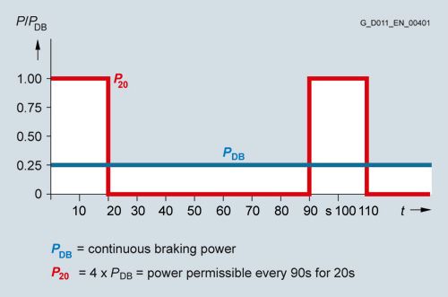
The following braking units are available for SINAMICS G120P Cabinet:
Order code
SINAMICS G120P Cabinet drive inverter cabinet units
Braking Module
Braking resistor
Option
Rated power
PDB
P20
RB
kW (hp)
kW (hp)
kW (hp)
Ω
380 ... 480 V 3 AC
L62
110 ... 560 (148 ... 751)
50 (67)
200 (268)
3.1 ±8 %
PDB: Rated power (continuous braking power).
P20: 20 s power referred to a braking interval of 90 s.
L83
Thermistor motor protection unit (alarm)Thermistor motor protection device for single-channel PTC temperature sensors (PTC resistors, type A) for alarm.
The thermistor motor protection unit is supplied with power and evaluated internally in the inverter. There is galvanic isolation between the supply voltage and the temperature measuring circuit.
Note:
The Control Unit has a monitoring channel to monitor the motor temperature as standard. This single-channel input supports PTC, KTY84, Pt1000 (from firmware V4.7.6) and also thermoclick sensors. The warning and fault thresholds are parameterizable. The temperature values acquired are automatically used for high-precision motor control.
Caution:
If there is no 230 V AC power supply in the customer installation, it is essential to select option K74 in order to ensure proper functioning of option L83.
L84
Thermistor motor protection unit (trip)Thermistor motor protection device for single-channel PTC temperature sensors (PTC resistors, type A) for trip.
The thermistor motor protection unit is supplied with power and evaluated internally in the inverter. There is galvanic isolation between the supply voltage and the temperature measuring circuit.
Note:
The Control Unit has a monitoring channel to monitor the motor temperature as standard. This single-channel input supports PTC, KTY84, Pt1000 (from firmware V4.7.6) and also thermoclick sensors. The warning and fault thresholds are parameterizable. The temperature values acquired are automatically used for high-precision motor control.
Caution:
If there is no 230 V AC power supply in the customer installation, it is essential to select option K74 in order to ensure proper functioning of option L84.
L86
PT100 evaluation unitThe Pt100 evaluation unit can monitor up to 6 temperature sensors. The following sensor types are supported: Pt100, Pt1000, KTY84, NTC and thermocouples.
The sensors can be connected in a two- or three-wire system. The limit values can be freely programmed for each channel. In the factory setting, the measuring channels are subdivided into two groups, each with 3 channels. With motors, for example, this means that three Pt100s in the stator windings and two Pt100s in the motor bearings can be monitored. Unused channels can be suppressed via parameters.
The output relays are integrated into the internal fault and shutdown sequence of the inverter. There is galvanic isolation between the supply voltage and the temperature measuring circuit.
The Control Unit has a monitoring channel to monitor the motor temperature as standard. This single-channel input supports PTC, KTY84, Pt1000 (from firmware V4.7.6) and also thermoclick sensors. The warning and fault thresholds are parameterizable. The temperature values acquired are automatically used for high-precision motor control.
Caution:
If there is no 230 V AC power supply in the customer installation, it is essential to select option K74 in order to ensure proper functioning of option L86.
M06
Base 100 mm high, RAL 7035The additional cabinet base allows larger bending radii for cables (cable entry from below) and enables them to be routed within the cabinet base. It is delivered completely assembled with the cabinet. The mounting height of the operator panel changes accordingly.
Note:
The cabinet base is coated as standard in RAL 7035.
M07
Cable compartment 200 mm high, RAL 7035The cable compartment is made of strong sheet steel and allows cables to be connected more flexibly (entry from below). It also allows routing of cables within the compartment. It is delivered completely assembled with the cabinet. The mounting height of the operator panel changes accordingly.
Note:
The cable compartment is coated as standard in RAL 7035.
M21
IP21 degree of protectionCabinet version in IP20, although with additional top cover or canopy. This increases the cabinet height by 300 mm.
For transport reasons, the top or drip protection covers are delivered separately and must be fitted on site.
Note:
The top or drip protection covers are painted in RAL 7035 as standard.
Caution:
If there is no 230 V AC power supply in the customer installation, it is essential to select option K74 in order to ensure a power supply to the fan for frame sizes HX and JX.
M23, M43, M54
Degrees of protection IP23, IP43, IP54When M23, M43 or M54 is selected, the inverter is equipped with a hood. This increases the cabinet height by 400 mm.
For transport reasons, the hoods are delivered separately and must be fitted by the customer.
Note:
The roof sections are colored RAL 7035 as standard. The molded plastic parts (e.g. ventilation grilles) have color RAL 7035 and cannot be coated.
Notice:
If there is no 230 V AC power supply in the customer installation for version A, it is essential to select option K74 in order to provide a power supply to the fan.
Q80 to Q85
Extension of the liability for defectsIt is possible to extend the liability for defect periods beyond the standard liability for defects period. The standard liability for defects period as listed in the standard conditions for the supply of services and products is 12 months.
The following extension periods are available:
Extension of the liability for defects period for inverters
Order No. supplement -Z with order code
Additional text
Q80
Extension of the liability for defects period by 12 months to a total of 24 months (2 years) from delivery
Q81
Extension of the liability for defects period by 18 months to a total of 30 months (2½ years) from delivery
Q82
Extension of the liability for defects period by 24 months to a total of 36 months (3 years) from delivery
Q83
Extension of the liability for defects period by 30 months to a total of 42 months (3½ years) from delivery
Q84
Extension of the liability for defects period by 36 months to a total of 48 months (4 years) from delivery
Q85
Extension of the liability for defects period by 48 months to a total of 60 months (5 years) from delivery
The currently valid conditions for extending the period of liability for defects can be found at
https://support.industry.siemens.com/cs/document/56715113T58, T60, T80, T85, T91
Rating plate dataAs standard, the rating plate is in English/German.
A rating plate in another language can be selected using the following order code for the option.
Order code
Rating plate language
T58
English/French
T60
English/Spanish
T80
English/Italian
T85
English/Russian
T91
English/Chinese
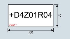
Y31
One-line label for system identification, 40 × 80 mm (1.57 x 3.15 in)Resopal labels (white with black lettering) for identifying the control cabinets are available. The labels are stuck to the cabinet door.
Dimensions H × W: 40 × 80 mm (1.57 x 3.15 in)
The text must be specified in plain text when ordering.
Field 1: Max. 9 characters, font size 10 mm (0.39 in)
Y32
Two-line label for system identification, 40 × 180 mm (1.57 x 7.09 in)Resopal labels (white with black lettering) for identifying the control cabinets are available. The labels are stuck to the cabinet door.
Dimensions H × W: 40 × 180 mm (1.57 x 7.09 in)
The text must be specified in plain text when ordering.
Field 1: Max. 9 characters, font size 10 mm (0.39 in)
Field 2: Max. 9 characters, font size 10 mm (0.39 in)
Field 3: Max. 20 characters, font size 10 mm.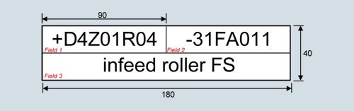
Y33
Four-line label for system identification, 40 × 180 mm (1.57 x 7.09 in)Resopal labels (white with black lettering) for identifying the control cabinets are available. The labels are stuck to the cabinet door.
Dimensions H × W: 40 × 180 mm (1.57 x 7.09 in)
The text must be specified in plain text when ordering.
Field 1: Max. 9 characters, font size 10 mm (0.39 in)
Field 2: Max. 20 characters, font size 6 mm (0.24 in)
Field 3: Max. 20 characters, font size 6 mm (0.24 in)
Field 4: Max. 20 characters, font size 6 mm (0.24 in)
Field 5: Max. 20 characters, font size 6 mm (0.24 in)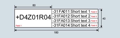
Технические данные
The most important directives and standards are listed below. These are used as basis for the SINAMICS G120P Cabinet drive inverter cabinet units and they must be carefully observed to achieve an EMC-compliant configuration that is safe both functionally and in operation.
European directives
2014/35/EU
Low-voltage directive:
Directive of the European Parliament and Council of February 26, 2014 for the harmonization of the laws of the member states relating to the provision of electrical equipment designed for use within certain voltage limits on the market (amended version)
2014/30/EU
EMC directive:
Directive of the European Parliament and Council of February 26, 2014 for the harmonization of the laws of the member states relating to electromagnetic compatibility (amended version)
2006/42/EC
Machinery directive:
The directive of the European Parliament and Council of May 17, 2006 on machinery and for changing Directive 95/16/EC (amendment)
European standards
EN 60146‑1‑1
Semiconductor converters – General requirements and line-commutated converters
Part 1‑1: Specification of basic requirements
EN 60204‑1
Electrical equipment of machines
Part 1: General requirements
EN 60529
Degrees of protection provided by enclosures (IP code)
EN 61800‑2
Adjustable speed electrical power drive systems
Part 2: General requirements – Rating specifications for low-voltage adjustable frequency a.c. power drive systems
EN 61800‑3
Adjustable speed electrical power drive systems
Part 3: EMC product standard including specific test methods
EN 61800-5-1
Adjustable speed electrical power drive systems
Part 5: Safety requirements
Main section 1: Electrical and thermal requirements
General technical specifications
Electrical specifications
Line voltages and power ranges
380 ... 480 V 3 AC ±10 %, 110 ... 560 kW (148 ... 751 hp)
500 ... 690 V 3 AC ±10 %, 500 ... 630 kW (671 ... 845 hp)
Output ranges
110 ... 560 kW (148 ... 751 hp)
Line system configurations
Grounded TN/TT systems and non-grounded IT systems
Line frequency
47 ... 63 Hz
Output frequency
0 ... 100 Hz
Offset factor cos φ
0.96
Power factor λ
0.75 ... 0.93
Efficiency
>98%
Overvoltage category
III to EN 61800‑5‑1
Closed-loop control modes
Vector control without sensor or U/f control
Fixed speeds
15 fixed speeds plus 1 minimum speed, parameterizable
(in the default setting, 3 fixed setpoints plus 1 minimum speed are selectable using terminal block/fieldbus system)Skipped speed ranges
4, parameterizable
Setpoint resolution of the Control Unit
0.01 Hz
12 bit analog
Braking operation
DC braking, dynamic braking with optional Braking Module
Mechanical specifications
Degree of protection
IP20 (higher degrees of protection up to IP54 optional)
Protection class
I acc. to EN 61800‑5‑1
Touch protection
According to EN 50274 and BGV A3 when used as intended
Cabinet system
Schäfer IS‑1, doors with double-barb lock, base plates with cable entry possibilities, crane transport aid
Paint finish
RAL 7035 (indoor requirements)
Type of cooling
Forced air cooling AF to EN 60146
Ambient conditions
Storage
Transport
Operation
Ambient temperature
-25 ... +55 °C
-25 ... +70 °C
above -40 °C for 24 hours0 ... 40 °C (32 ... 104 °F)
up to 50 °C (122 °F) see derating dataRelative humidity
(condensation not permissible)
5 ... 95 %
Class 1K4 to EN 60721‑3‑1
5 ... 95 %
Class 2K3 to EN 60721‑3‑2
5 ... 95 %
Class 3K3 to EN 60721‑3‑3
Environmental class/harmful chemical substances
Class 1C2 acc. to EN 60721‑3‑1
Class 2C2 acc. to EN 60721‑3‑2
Class 3C2 acc. to EN 60721‑3‑3
Organic/biological influences
Class 1B1 acc. to EN 60721‑3‑1
Class 2B1 acc. to EN 60721‑3‑2
Class 3B1 according to EN 60721‑3‑3
Restriction: No conductive dust particles permittedDegree of pollution
2 acc. to EN 61800‑5‑1
Installation altitude
Up to 1000 m (3281 ft) above sea level without derating
> 1000 m (3281 ft) see derating dataMechanical strength
Storage
Transport 2)
Operation
Vibratory load
Class 1M2 acc. to EN 60721‑3‑1
Class 2M2 acc. to EN 60721‑3‑2
Class 3M2 acc. to EN 60721‑3‑3
- Deflection
1.5 mm at 5 ... 9 Hz
3.5 mm at 2 ... 9 Hz
0.075 mm at 10 ... 58 Hz
- Acceleration
5 m/s2 at > 9 ... 200 Hz
10 m/s2 at > 9 ... 200 Hz
10 m/s2 at > 58 ... 200 Hz
Shock load
Class 1M2 acc. to EN 60721‑3‑1
Class 2M2 acc. to EN 60721‑3‑2
Class 3M2 acc. to EN 60721‑3‑3
- Acceleration
40 m/s2 at 22 ms
150 m/s2 at 11 ms
50 m/s2 (5 × g)/30 ms
150 m/s2 (15 × g)/11 msStandards
Compliance with standards
cULus, CE, RCM, EAC, KC, SEMI F47 3)
CE marking
According to EMC Directive 2014/30/EU, Low Voltage Directive 2014/35/EU, Machinery Directive 2006/42/EC
Radio interference suppression
The SINAMICS G120P Cabinet inverter systems are not designed for connection to the public power network ("first environment"). Radio interference suppression is compliant with the EMC product standard for variable-speed drives EN 61800-3 "Second environment" (industrial line supplies). The equipment can cause electromagnetic interference when it is connected to the public network. However, if supplementary measures are taken (e.g. line filter, see option L00) operation in the "first environment" is possible.
Deviations from the specified classes are underlined.
1) For the option L01, the line voltage is limited to 380 to 415 V AC ± 10%.
2) In transport packaging.
3) SEMI F47 for frame size JX available soon
Line voltage 380 ... 480 V 3 AC
SINAMICS G120P Cabinet drive inverter cabinet units
6SL3710-1PE32‑1.A0-Z
6SL3710-1PE32‑5.A0-Z
6SL3710-1PE33‑0.A0-Z
6SL3710-1PE33‑7.A0-Z
6SL3710-1PE34‑6.A0-Z
Rated power
- At IL 400 V/50 Hz 1)
kW
110
132
160
200
250
- At IL 460 V/60 Hz 2)
hp
125
150
200
250
300
- At IH 400 V/50 Hz 1)
kW
90
110
132
160
200
- At IH 460 V/60 Hz 2)
hp
100
100
150
200
200
Output current
- Rated current Irated (400 V ±10 %)
A
205
245
300
370
460
- Rated current Irated (480 V ±10 %)
A
160
184
245
308
369
- Base-load current IL (400 V ±10 %) 3)
A
200
240
290
360
450
- Base-load current IL (480 V ±10 %) 3)
A
156
180
240
302
361
- Base-load current IH (400 V ±10 %) 4)
A
164
196
240
296
368
- Base-load current IH (480 V ±10 %) 4)
A
128
147
196
247
295
- Output current, max.
A
270
324
392
486
608
Input current
- Rated current Irated (400 V ±10 %) 5)
A
218
262
317
375
469
- Rated current Irated (480 V ±10 %) 5)
A
171
197
262
314
376
- Base-load current IL (400 V ±10 %) 3)
A
213
257
307
365
459
- Base-load current IL (480 V ±10 %) 3)
A
167
193
257
308
368
- Base-load current IH (400 V ±10 %) 4)
A
175
210
254
300
375
- Base-load current IH (480 V ±10 %) 4)
A
137
157
210
251
301
- Input current, max.
A
288
347
415
493
620
Current requirement, 24 V DC auxiliary power supply 6)
- Version A
A
1
1
1
1
1
- Version C
A
0.5
0.5
0.5
0.5
0.5
Short-circuit current rating acc. to IEC
in conjunction with the specified fuses without/with Option L26
kA
65/65
65/65
65/65
65/65
65/50
Minimum short-circuit current 7)
- For 3NE1 fuses
A
3000
3600
4400
5200
7000
- For 3NA3 fuses
A
5800
7300
9500
14000
20000
Power loss, max.
at Irated (400 V/40 °C)
- Version A
kW
3.377
3.939
4.543
5.681
6.376
- Version C
kW
2.831
3.255
3.901
4.777
5.482
Coolant
of air
of air
of air
of air
of air
Coolant requirements
m3/s (ft3/s)
0.21 (7.4)
0.21 (7.4)
0.21 (7.4)
0.21 (7.4)
0.21 (7.4)
Sound pressure level LpA(1 m) at 50/60 Hz
- Version A
dB
66/66
66/66
66/66
66/66
66/66
- Version C
dB
63/63
63/63
63/63
63/63
63/63
Cable length, max.
between Power Module and motor
- When compliant with Categories C2 and C3 according to EN 61800‑3
shielded
m (ft)
100 (328.10)
100 (328.10)
100 (328.10)
100 (328.10)
100 (328.10)
- When non-compliant with the limit values for RI suppression and without output reactor
unshielded
m (ft)
200 (656)
200 (656)
200 (656)
200 (656)
200 (656)
- When non-compliant with the limit values for RI suppression with output reactor
shielded/unshielded
m (ft)
300/450 (984.30/1476.45)
300/450 (984.30/1476.45)
300/450 (984.30/1476.45)
300/450 (984.30/1476.45)
300/450 (984.30/1476.45)
Dimensions
- Width for
version A/C
mm (in)
1000/600 (39.37/23.62)
1000/600 (39.37/23.62)
1000/600 (39.37/23.62)
1000/600 (39.37/23.62)
1000/600 (39.37/23.62)
- Height8)
mm (in)
2000 (78.7)
2000 (78.7)
2000 (78.7)
2000 (78.7)
2000 (78.7)
- Depth
mm (in)
600 (23.62)
600 (23.62)
600 (23.62)
600 (23.62)
600 (23.62)
Frame size
GX
GX
GX
GX
GX
Weight
Versions A/C
(degree of protection IP20, without options)kg (lb)
360/290 (794/639)
360/290 (794/639)
370/290 (816/639)
380/300 (838/661)
400/300 (882/661)
1) Rated power of a typ. 4-pole standard induction motor based on base-load current IL or IH at 400 V 3 AC/50 Hz.
2) Rated power of a typ. 4-pole standard induction motor based on base-load current IL or IH at 460 V 3 AC/60 Hz.
3) The base-load current IL is based on a duty cycle of 110% for 60 s or 135 % for 3 s with a duty cycle duration of 300 s (see overload capability characteristics).
4) The base-load current IH is based on a duty cycle of 150% for 60 s with a duty cycle duration of 300 s (see overload capability characteristics).
5) The current values given here are based on the rated output current.
6)If the drive closed-loop control is still to remain active when the main line supply fails, then the equipment must be provided with an external 24 V DC supply.
7) 10 ms value from current-time characteristic for reliable tripping of installed protection devices. If the minimum short circuit current is not reached, the tripping time of the fuses is increased, which can lead to damage.
8)Version A: The cabinet height increases by 300 mm with IP20 and IP21 degrees of protection, and by 400 mm with IP23, IP43 and IP54 degrees of protection.Version C: The cabinet height increases by 300 mm for IP21 degree of protection, and by 400 mm for IP23, IP43 and IP54 degrees of protection.
Note:
The power data in hp units are based on the NEC/CEC standards for the North American market.
Information on the line connection, motor connection and cabinet grounding can be found in section Cable cross-sections and connections.
Line voltage 380 ... 480 V 3 AC
SINAMICS G120P Cabinet drive inverter cabinet units
6SL3710-1PE35‑8.A0-Z
6SL3710-1PE36‑6.A0-Z
6SL3710-1PE37‑4.A0-Z
Rated power
- At IL 400 V/50 Hz 1)
kW
315
355
400
- At IL 460 V/60 Hz 2)
hp
400
450
500
- At IH 400 V/50 Hz 1)
kW
250
250
315
- At IH 460 V/60 Hz 2)
hp
300
300
350
Output current
- Rated current Irated (400 V ±10 %)
A
585
655
735
- Rated current Irated (480 V ±10 %)
A
487
526
602
- Base-load current IL (400 V ±10 %) 3)
A
570
640
720
- Base-load current IL (480 V ±10 %) 3)
A
477
515
590
- Base-load current IH (400 V ±10 %) 4)
A
468
491
551
- Base-load current IH (480 V ±10 %) 4)
A
390
394
452
- Output current, max.
A
770
864
972
Input current
- Rated current Irated (400 V ±10 %) 5)
A
597
668
750
- Rated current Irated (480 V ±10 %) 5)
A
497
536
614
- Base-load current IL (400 V ±10 %) 3)
A
585
654
735
- Base-load current IL (480 V ±10 %) 3)
A
486
525
602
- Base-load current IH (400 V ±10 %) 4)
A
477
501
562
- Base-load current IH (480 V ±10 %) 4)
A
397
402
461
- Input current, max.
A
785
881
992
Current requirement, 24 V DC auxiliary power supply 6)
- Version A
A
1
1
1
- Version C
A
0.5
0.5
0.5
Short-circuit current rating acc. to IEC
in conjunction with the specified fuses
without/with Option L26kA
65/50
65/50
65/50
Minimum short-circuit current 7)
- For 3NE1 fuses
A
10000
11000
13000
- For 3NA3 fuses
A
20000
30000
30000
Power loss, max.
at Irated (400 V/40 °C)
- Version A
kW
8.478
9.443
9.907
- Version C
kW
7.143
8.026
8.824
Coolant
of air
of air
of air
Coolant requirements
m3/s (ft3/s)
0.6 (21.2)
0.6 (21.2)
0.6 (21.2)
Sound pressure level LpA(1 m) at 50/60 Hz
- Version A
dB
69/69
69/69
69/69
- Version C
dB
66/66
66/66
66/66
Cable length, max.
between Power Module and motor
- When compliant with Categories C2 and C3 according to EN 61800‑3
shielded
m (ft)
100 (328.10)
100 (328.10)
100 (328.10)
- When non-compliant with the limit values for RI suppression and without output reactor
unshielded
m (ft)
200 (656.20)
200 (656.20)
200 (656.20)
- When non-compliant with the limit values for RI suppression with output reactor
shielded/unshielded
m (ft)
300/450 (984.30/1476.45)
300/450 (984.30/1476.45)
300/450 (984.30/1476.45)
Dimensions
- Width for
version A/C
mm (in)
1200 9)/800
1200 9)/800
1200 9)/800
- Height8)
mm (in)
2000 (78.7)
2000 (78.7)
2000 (78.7)
- Depth
mm (in)
600 (23.62)
600 (23.62)
600 (23.62)
Frame size
HX
HX
HX
Weight
Versions A/C
(degree of protection IP20, without options)kg (lb)
500/430 (1102/948)
500/440 (1102/970)
530/440 (1169/970)
1) Rated power of a typ. 4-pole standard induction motor based on base-load current IL or IH at 400 V 3 AC/50 Hz.
2) Rated power of a typ. 4-pole standard induction motor based on base-load current IL or IH at 460 V 3 AC/60 Hz.
3) The base-load current IL is based on a duty cycle of 110% for 60 s or 135 % for 3 s with a duty cycle duration of 300 s (see overload capability characteristics).
4) The base-load current IH is based on a duty cycle of 150% for 60 s with a duty cycle duration of 300 s (see overload capability characteristics).
5) The current values given here are based on the rated output current.
6)If the drive closed-loop control is still to remain active when the main line supply fails, then the equipment must be provided with an external 24 V DC supply.
7) 10 ms value from current-time characteristic for reliable tripping of installed protection devices. If the minimum short circuit current is not reached, the tripping time of the fuses is increased, which can lead to damage.
8) The cabinet height increases by 300 mm (11.81 in) for IP21 degree of protection, and by 400 mm (15.75 in) for IP23, IP43 and IP54 degrees of protection.
9) The specified cabinet widths increase depending on the options selected. For details, see description of option L01.
Note:
The power data in hp units are based on the NEC/CEC standards for the North American market.
Information on the line connection, motor connection and cabinet grounding can be found in section Cable cross-sections and connections.
Line voltage 380 ... 480 V 3 AC
SINAMICS G120P Cabinet drive inverter cabinet units
6SL3710-1PE38-4AA0-Z
6SL3710-1PE38-8AA0-Z
6SL3710-1PE41-0AA0-Z
Rated power
- At IL 400 V/50 Hz 1)
kW
450
500
560
- At IL 460 V/60 Hz 2)
hp
500
600
700
- At IH 400 V/50 Hz 1)
kW
355
400
450
- At IH 460 V/60 Hz 2)
hp
450
500
500
Output current
- Rated current Irated (400 V ±10 %)
A
840
910
1021
- Rated current Irated (480 V ±10 %)
A
677
739
847
- Base-load current IL (400 V ±10 %) 3)
A
820
890
1000
- Base-load current IL (480 V ±10 %) 3)
A
663
724
830
- Base-load current IH (400 V ±10 %) 4)
A
672
728
786
- Base-load current IH (480 V ±10 %) 4)
A
542
591
652
- Output current, max.
A
1107
1202
1350
Input current
- Rated current Irated (400 V ±10 %) 5)
A
870
945
1061
- Rated current Irated (480 V ±10 %) 5)
A
702
767
880
- Base-load current IL (400 V ±10 %) 3)
A
850
925
1039
- Base-load current IL (480 V ±10 %) 3)
A
687
751
862
- Base-load current IH (400 V ±10 %) 4)
A
696
756
816
- Base-load current IH (480 V ±10 %) 4)
A
561
614
677
- Input current, max.
A
1147
1248
1402
Current requirement, 24 V DC auxiliary power supply 6)
A
1
1
1
Short-circuit current rating acc. to IEC
in conjunction with the specified fuses
without/with option L26kA
65/65
65/65
65/65
Minimum short-circuit current 7)
- For 3NE1 fuses
A
10400
14000
16000
- For 3NA3 fuses
A
40000
40000
52000
Power loss, max.
At Irated (400 V/40 °C)
kW
10.95
11.354
12.997
Coolant
Air
Air
Air
Coolant requirements
m3/s (ft3/s)
0.7 (24.7)
0.7 (24.7)
0.7 (24.7)
Sound pressure level LpA(1 m) at 50/60 Hz
dB
69/69
69/69
69/69
Cable length, max.
between Power Module and motor
- When compliant with Categories C2 and C3 according to EN 61800‑3
shielded
m (ft)
100 (328)
100 (328)
100 (328)
- When non-compliant with the limit values for RI suppression and without output reactor
unshielded
m (ft)
200 (656)
200 (656)
200 (656)
- When non-compliant with the limit values for RI suppression with output reactor
shielded/unshielded
m (ft)
300/450 (984/1476)
300/450 (984/1476)
300/450 (984/1476)
Dimensions
- Width
mm (in)
1200 (47.2) 9)
1200 (47.2) 9)
1200 (47.2) 9)
- Height8)
mm (in)
2000 (78.7)
2000 (78.7)
2000 (78.7)
- Depth
mm (in)
600 (23.6)
600 (23.6)
600 (23.6)
Frame size
JX
JX
JX
Weight
(degree of protection IP20, without options)
kg (lb)
655 (1444)
676 (1490)
681 (1501)
1) Rated power of a typ. 4-pole standard induction motor based on base-load current IL or IH at 400 V 3 AC/50 Hz.
2) Rated power of a typ. 4-pole standard induction motor based on base-load current IL or IH at 460 V 3 AC/60 Hz.
3) The base-load current IL is based on a duty cycle of 110 % for 60 s or 135 % for 3 s with a duty cycle duration of 300 s (see overload capability characteristics).
4) The base-load current IH is based on a duty cycle of 150 % for 60 s with a duty cycle duration of 300 s (see overload capability characteristics).
5) The current values given here are based on the rated output current.
6) If the drive closed-loop control is still to remain active when the main line supply fails, then the inverter must be provided with an external 24 V DC supply.
7) 10 ms value from current-time characteristic for reliable tripping of installed protection devices. If the minimum short circuit current is not reached, the tripping time of the fuses is increased, which can lead to damage.
8) The cabinet height increases by 300 mm for degree of protection IP21, and by 400 mm (15.7 in) for degrees of protection IP23, IP43 and IP54.
9) The specified cabinet widths increase depending on the options selected. For details, see description of options L00 and L01.
Note:
The power data in hp units are based on the NEC/CEC standards for the North American market.
Information on the line connection, motor connection and cabinet grounding can be found in section Cable cross-sections and connections.
Line voltage 500 ... 690 V 3 AC
SINAMICS G120P Cabinet drive inverter cabinet units
6SL3710-1PG35-8AA0-Z
6SL3710-1PG36-5AA0-Z
6SL3710-1PG37-2AA0-Z
Rated power
- At IL 690 V/50 Hz 1)
kW
500
560
630
- At IL 575 V/60 Hz 2)
hp
500
600
700
- At IH 690 V/50 Hz 1)
kW
450
500
560
- At IH 575 V/60 Hz 2)
hp
450
500
500
Output current
- Rated current Irated (500 V ±10 %)
A
581
654
725
- Rated current Irated (600 V ±10 %)
A
557
623
693
- Rated current Irated (690 V ±10 %)
A
535
595
665
- Base-load current IL (500 V ±10 %) 3)
A
569
640
710
- Base-load current IL (690 V ±10 %) 3)
A
520
580
650
- Base-load current IH (500 V ±10 %) 4)
A
482
523
580
- Base-load current IH (690 V ±10 %) 4)
A
444
476
532
- Output current, max.
A
768
864
959
Input current
- Rated current Irated (500 V ±10 %) 5)
A
596
679
753
- Rated current Irated (600 V ±10 %) 5)
A
578
647
720
- Rated current Irated (690 V ±10 %) 5)
A
555
618
690
- Base-load current IL (500 V ±10 %) 3)
A
591
665
737
- Base-load current IL (690 V ±10 %) 3)
A
540
602
675
- Base-load current IH (500 V ±10 %) 4)
A
501
543
602
- Base-load current IH (690 V ±10 %) 4)
A
461
494
552
- Input current, max.
A
798
897
995
Current requirement, 24 V DC auxiliary power supply 6)
A
1
1
1
Short-circuit current rating acc. to IEC
in conjunction with the specified fuses
kA
65
65
65
Minimum short-circuit current 7)
- For 3NE1 fuses
A
10000
11000
13000
- For 3NA3 fuses
A
16000
20000
21000
Power loss, max.
At Irated (500 V/40 °C)
kW
9.122
9.972
11.221
Coolant
Air
Air
Air
Coolant requirements
m3/s (ft3/s)
0.7 (24.7)
0.7 (24.7)
0.7 (24.7)
Sound pressure level LpA(1 m) at 50/60 Hz
dB
69/69
69/69
69/69
Cable length, max.
between Power Module and motor
- When compliant with Categories C2 and C3 according to EN 61800‑3
shielded
m (ft)
100 (328)
100 (328)
100 (328)
- When non-compliant with the limit values for RI suppression and without output reactor
unshielded
m (ft)
200 (656)
200 (656)
200 (656)
- When non-compliant with the limit values for RI suppression with output reactor
shielded/unshielded
m (ft)
300/450 (984/1476)
300/450 (984/1476)
300/450 (984/1476)
Dimensions
- Width
mm (in)
1200 (47.2) 9)
1200 (47.2) 9)
1200 (47.2) 9)
- Height8)
mm (in)
2000 (78.7)
2000 (78.7)
2000 (78.7)
- Depth
mm (in)
600 (23.6)
600 (23.6)
600 (23.6)
Frame size
JX
JX
JX
Weight
(degree of protection IP20, without options)
kg (lb)
654 (1442)
697 (1537)
716 (1579)
1) Rated power of a typ. 4-pole standard induction motor based on base-load current IL or IH at 690 V 3 AC/50 Hz.
2) Rated power of a typ. 4-pole standard induction motor based on base-load current IL or IH at 575 V 3 AC/60 Hz.
3) The base-load current IL is based on a duty cycle of 110 % for 60 s or 135 % for 3 s with a duty cycle duration of 300 s (see overload capability characteristics).
4) The base-load current IH is based on a duty cycle of 150 % for 60 s with a duty cycle duration of 300 s (see overload capability characteristics).
5) The current values given here are based on the rated output current.
6)If the drive closed-loop control is still to remain active when the main line supply fails, then the inverter must be provided with an external 24 V DC supply.
7) 10 ms value from current-time characteristic for reliable tripping of installed protection devices. If the minimum short circuit current is not reached, the tripping time of the fuses is increased, which can lead to damage.
8) The cabinet height increases by 300 mm for degree of protection IP21, and by 400 mm for degrees of protection IP23, IP43 and IP54.
9) The specified cabinet widths increase depending on the options selected. For details, see description of option L00.
Note:
The power data in hp units are based on the NEC/CEC standards for the North American market.
Information on the line connection, motor connection and cabinet grounding can be found in section Cable cross-sections and connections.
- Version A (110 kW to 630 kW - 148 to 845 hp)