
- Каталог оборудования Siemens
- Каталог продуктов Siemens Industry
- Приводная техника
- Техника автоматизации
- Energy
- Автоматизация и безопасность зданий
- Низковольтная коммутационная техника
- Технология безопасности
- Системные решения и продукты для отраслей
- Автомобильная промышленность
- Биотопливо
- Химическая промышленность
- Пищевая промышленность
- Производственные машины
- Packaging machines
- Printing presses
- Textile machines
- Converting
- Metal forming technology
- Handling systems
- Непрерывное преобразование листового материала - Converting
- Печать
- Манипуляторы
- Пластик
- Текстиль
- Обработка металлов давлением
- Упаковка
- Компоненты автоматизации для станков
- SINUMERIK 808 with SINAMICS V60/V70
- SINUMERIK 828 with SINAMICS S120
- SINUMERIK 840 with SINAMICS S120
- Introduction SINUMERIK 840D sl with SINAMICS S120
- SINUMERIK CNC control
- SINUMERIK Operate
- SINUMERIK Integrate
- SINAMICS S120 drive system
- SIMOTICS motors
- MOTION-CONNECT connection systems
- Lifecycle Services
- SINUMERIK Solution Partners
- Certificates of suitability (approvals)
- Glossary SINUMERIK 840
- Glossary SINAMICS S120 drive system
- List of abbreviations
- Приводные применения
- Горная и металлургическая промышленность
- Нефтегазовая промышленность
- Фармацевтическая промышленность
- Бумажная промышленность
- Солнечная энергетика
- Транспорт, инфраструктура, логистика
- Вода и водоподготовка
- Сбыт электроэнергии
- Возобновляемые источники энергии
- Отраслевые решения
- Отраслевые продукты
- Сервис
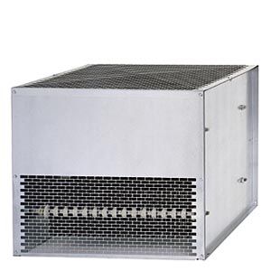
Braking resistors for chassis format
- Заказные данные (6)
- Информационные материалы
Информационные материалы
The excess energy of the DC link is dissipated via the braking resistor.
The braking resistor is connected to a Braking Module. The braking resistor is positioned outside the cabinet or switchgear room. This arrangement enables the resulting heat losses to be dissipated, thereby allowing a corresponding reduction in the level of air conditioning required.
2 braking resistors with different rated and peak power values are available for chassis format units.
The braking resistor is monitored on the basis of the mark-space ratio. A temperature switch (NC contact) is also fitted. This responds when the maximum permissible temperature is exceeded and can be evaluated by a controller.
Характеристика

Load diagram for Braking Module and braking resistor in chassis format
Технические данные
DC link voltage 510 ... 720 V DC
Braking resistor
6SL3000‑1BE31‑3AA0
6SL3000‑1BE32‑5AA0
Resistance
Ω
4.4
2.2
Rated power PDB
kW
25
50
Peak power Pmax
kW
125
250
Load duration
for peak output
s
15
15
Cycle duration
of braking duty cycle
s
90
90
Current, max.
A
189
378
Cable entry
Via M50 cable gland
Via M50 cable gland
Power connection
Via M10 stud
Via M10 stud
- Conductor cross-section, max.
mm2
50
70
Degree of protection
IP20
IP20
Dimensions
- Width
mm (in)
740 (29.1)
810 (31.9)
- Height
mm (in)
605 (23.8)
1325 (52.2)
- Depth
mm (in)
485 (19.1)
485 (19.1)
Weight, approx.
kg (lb)
50 (110)
120 (265)
Approvals, according to
cURus
cURus
Suitable for Braking Module in chassis format
Type
6SL3300‑1AE31‑3AA0
6SL3300‑1AE32‑5 . A0
DC link voltage 675 ... 900 V DC
Braking resistor
6SL3000‑1BF31‑3AA0
6SL3000‑1BF32‑5AA0
Resistance
Ω
6.8
3.4
Rated power PDB
kW
25
50
Peak power Pmax
kW
125
250
Load duration
for peak output
s
15
15
Cycle duration
of braking duty cycle
s
90
90
Current, max.
A
153
306
Cable entry
Via M50 cable gland
Via M50 cable gland
Power connection
Via M10 stud
Via M10 stud
- Conductor cross-section, max.
mm2
50
70
Degree of protection
IP20
IP20
Dimensions
- Width
mm (in)
740 (29.1)
810 (31.9)
- Height
mm (in)
605 (23.8)
1325 (52.2)
- Depth
mm (in)
485 (19.1)
485 (19.1)
Weight, approx.
kg (lb)
50 (110)
120 (265)
Approvals, according to
cURus
cURus
Suitable for Braking Module in chassis format
Type
6SL3300‑1AF31‑3AA0
6SL3300‑1AF32‑5 . A0
DC link voltage 890 ... 1035 V DC
Braking resistor
6SL3000‑1BH31‑3AA0
6SL3000‑1BH32‑5AA0
Resistance
Ω
9.8
4.9
Rated power PDB
kW
25
50
Peak power Pmax
kW
125
250
Load duration
for peak power
s
15
15
Cycle duration
of braking duty cycle
s
90
90
Current, max.
A
125
255
Cable entry
Via M50 cable gland
Via M50 cable gland
Power connection
Via M10 stud
Via M10 stud
- Conductor cross-section, max.
mm2
50
70
Degree of protection
IP20
IP20
Dimensions
- Width
mm (in)
740 (29.1)
810 (31.9)
- Height
mm (in)
605 (23.8)
1325 (52.2)
- Depth
mm (in)
485 (19.1)
485 (19.1)
Weight, approx.
kg (lb)
50 (110)
120 (265)
Approvals, according to
–
–
Suitable for Braking Module in chassis format
Type
6SL3300‑1AH31‑3AA0
6SL3300‑1AH32‑5 . A0