
- Каталог оборудования Siemens
- Каталог продуктов Siemens Industry
- Приводная техника
- Техника автоматизации
- Системы автоматизации
- Системы визуализации SIMATIC HMI
- Системы идентификации
- Промышленные коммуникации SIMATIC NET
- Промышленные аппараты управления SIRIUS
- Промышленные информационные технологии
- Управление на базе РС
- Системы управления процессом
- Контрольно-измерительные приборы
- Анализаторы процесса
- Блоки питания SITOP
- Продукты для специальных требований
- Модули с расширенным температурным диапазоном SIPLUS
- Промышленные системы автоматизации SIMATIC
- Программируемые контроллеры
- Распределенная периферия SIMATIC ET200
- SIPLUS ET 200 systems for the control cabinet
- SIPLUS ET 200SP
- Интерфейсные модули SIPLUS
- SIPLUS extreme RAIL interface modules
- Модули ввода-вывода SIPLUS
- Модули ввода дискретных сигналов SIPLUS
- Модули вывода дискретных сигналов SIPLUS
- Модули ввода аналоговых сигналов SIPLUS
- Модули вывода аналоговых сигналов SIPLUS
- SIPLUS technology modules
- SIPLUS Communication
- SIPLUS F модули
- SIPLUS extreme RAIL digital input modules
- SIPLUS extreme RAIL digital output modules
- SIPLUS extreme RAIL analog input modules
- SIPLUS extreme RAIL analog output modules
- SIPLUS extreme RAIL analog output modules
- SIPLUS extreme RAIL Communication modules
- Базовые блоки SIPLUS
- SIPLUS BusAdapter
- SIPLUS extreme RAIL BaseUnits
- SIPLUS extreme RAIL BusAdapter
- SIPLUS ET 200S
- SIPLUS ET 200MP
- ET 200M
- SIPLUS ET 200SP
- Компоненты SIPLUS PROFIBUS для ET 200
- SIPLUS ET 200 systems for the control cabinet
- Система управления перемещением SIMOTION
- Распределенные системы управления
- Системы оперативного управления и мониторинга
- Промышленные коммуникации
- Аппаратура управления
- Блоки питания
- Дополнения SIPLUS
- Промышленные системы автоматизации SIMATIC
- Системы телеметрии
- IO Systems for heating units
- Automatic door controls
- Condition monitoring systems
- Time synchronization
- Модули с расширенным температурным диапазоном SIPLUS
- Energy
- Автоматизация и безопасность зданий
- Низковольтная коммутационная техника
- Технология безопасности
- Системные решения и продукты для отраслей
- Сервис
SIPLUS extreme RAIL analog output modules
- Заказные данные (1)
- Аксессуары (4)
- Информационные материалы
Информационные материалы
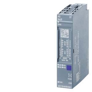
- 4-channel analog output (AQ) modules
- Approved in accordance with the EN 50155, EN 15121, EN 50124, EN 50125 and EN 45545 railway standards for use in rail traffic
For different requirements, the digital output modules offer:
- BaseUnits for single or multiple-conductor connection with automatic slot coding
- Individual system-integrated load group formation with self-assembling voltage distribution bars (a separate power module is no longer required for ET 200SP)
- Option for connecting current and voltage actuators
- Clear labeling on front of module
- LEDs for diagnostics, status, supply voltage and faults
- Electronically readable and non-volatile writable rating plate (I&M data 0 to 3)
- Optional accessories
- Labeling strips (film or card)
- Equipment labeling plate
- Color-coded label with module-specific CC Code
- Shielding terminal
A quick and clear comparison of the functions of the AQ modules is offered by the TIA Selection Tool.
Overview of analog output modules
Analog output
PU
Article No.
CC-Code
BU type
AQ 4 x U/I ST
1
6AG2135-6HD00-4BA1
CC00
A0, A1
Overview of BaseUnits
BaseUnit
PU
Article No.
CC-Codes for process terminals
CC-Codes for AUX terminals
BU type A0
- New load group (light)
- 16 process terminals
- With 10 AUX terminals
1
6AG2193-6BP20-4DA0
CC01 to CC05
CC71 to CC73
BU type A0
- New load group (light)
- 16 process terminals
- Without AUX terminals
1
6AG2193-6BP00-4DA0
CC01 to CC05
--
BU type A0
- Forwarding of load group (dark)
- 16 process terminals
- With 10 AUX terminals
1
6AG2193-6BP20-4BA0
CC01 to CC05
CC71 to CC73
BU type A0
- Forwarding of load group (dark)
- 16 process terminals
- Without AUX terminals
1
6AG2193-6BP00-4BA0
CC01 to CC05
--
Область применения
The analog output modules enable analog actuators (proportional valves, drives, etc.) to be controlled.
Дизайн
Usable BaseUnits (BU)
BaseUnits with an appropriate number of terminals are available for single or multi-conductor connection.
All variants that correspond to the BU type of the I/O module used can be used as BaseUnits (see Selection and ordering data).
Load group formation
A light-colored BU separates the self-assembling, internal voltage buses (P1, P2, AUX) and thus opens a new load group. The supply voltage of a load group must be fed in at the light BU of this load group.
A dark BU forwards the supply voltage of the adjacent light BU on the left via the self-assembling voltage buses P1, P2 and AUX. A new infeed is therefore only required on the next light BU to the right. The setting of a further light BU is required whenever
- a new load group is to be formed (for example, for isolating the supply voltage from module groups) or
- the maximum current simultaneously required by the load group exceeds the permissible limit of 10 A.
Color identification of the terminals
The potentials at the terminals of the BaseUnit are defined by the inserted I/O module in each case. To prevent wiring faults, the potentials of the terminals can optionally be identified by means of module-specific color-coded labels. The color-coded label that matches the respective I/O module is defined by the color code CCxx of the I/O module. This color code is also printed on the front of the module.
In BaseUnits with the additional ten internally jumpered AUX terminals, these can also be identified with color-coded labels. For the ten AUX terminals, color-coded labels are available in red, blue, and yellow/green.
Labeling
Labeling strips
Labeling strips can be inserted on the front of the interface modules or I/O modules and individually labeled via STEP 7, macros, etc. No special additional holder is required. If required, they can be easily replaced with the component.
Equipment labeling plates
Equipment labeling plates enable the equipment to be easily identified (e.g. compliant with EN 81346). They are easily plugged onto the required component (interface modules, I/O modules and BaseUnits) and when required, they can be easily replaced with the component.
The following labeling components are available:
- Film labeling strips, light-gray, roll with 500 strips, perforated, for thermal transfer printers
- Film labeling strips, yellow, roll with 500 strips, perforated, for thermal transfer printers
- Card labeling strips (180 g/m2), light gray, DIN A4 sheets with 100 strips each, perforated, for laser printer
- Card labeling strips (180 g/m2), yellow, DIN A4 sheets with 100 strips each, perforated, for laser printer
- Equipment labeling plates, white, ten sheets each with 16 labels, for thermal transfer card printers or labels
Технические данные
Order number
6AG2135-6HD00-4BA1
SIPLUS ET 200SP AQ 4XU/I ST TX RAIL
General information
Product type designation
ET 200SP, AQ 4xU/I Standard
Product function
● I&M data
Yes; I&M0 to I&M3
● Output range scalable
No
Operating mode
● Oversampling
No
● MSO
No
CiR – Configuration in RUN
Reparameterization possible in RUN
Yes
Calibration possible in RUN
No
Supply voltage
Type of supply voltage
DC
Rated value (DC)
24 V
Reverse polarity protection
Yes
Analog outputs
Number of analog outputs
4; > +60 °C max. 2x +/- 10 V permissible
Cycle time (all channels), min.
5 ms
Analog output with oversampling
No
Output ranges, voltage
● 0 to 10 V
Yes; 15 bit
● 1 V to 5 V
Yes; 13 bit
● -5 V to +5 V
Yes; 15 bit incl. sign
● -10 V to +10 V
Yes; 16 bit incl. sign
Output ranges, current
● 0 to 20 mA
Yes; 15 bit
● -20 mA to +20 mA
Yes; 16 bit incl. sign
● 4 mA to 20 mA
Yes; 14 bit
Connection of actuators
● for voltage output two-wire connection
Yes
● for voltage output four-wire connection
Yes
● for current output two-wire connection
Yes
Load impedance (in rated range of output)
● with voltage outputs, min.
2 kΩ
● with voltage outputs, capacitive load, max.
1 µF
● with current outputs, max.
500 Ω
● with current outputs, inductive load, max.
1 mH
Cable length
● shielded, max.
1 000 m; 200 m for voltage output
Settling time
● for resistive load
0.1 ms
● for capacitive load
1 ms
● for inductive load
0.5 ms
Errors/accuracies
Basic error limit (operational limit at 25 °C)
● Voltage, relative to output range, (+/-)
0.3 %
● Current, relative to output range, (+/-)
0.3 %
Isochronous mode
Isochronous operation (application synchronized up to terminal)
No
Interrupts/diagnostics/status information
Diagnostics function
Yes
Substitute values connectable
Yes
Alarms
● Diagnostic alarm
Yes
Diagnostic messages
● Monitoring the supply voltage
Yes
● Wire-break
Yes
● Short-circuit
Yes
● Group error
Yes
● Overflow/underflow
Yes
Diagnostics indication LED
● Monitoring of the supply voltage (PWR-LED)
Yes; green PWR LED
● Channel status display
Yes; Green LED
● for channel diagnostics
No
● for module diagnostics
Yes; green/red DIAG LED
Potential separation
Potential separation channels
● between the channels and backplane bus
Yes
Isolation
Isolation tested with
707 V DC (type test) and according to EN 50155 (routine test)
Standards, approvals, certificates
Railway application
● EN 50121-3-2
Yes; EMC for rail vehicles
● EN 50121-4
Yes; EMC for signal and telecommunications systems
● EN 50124-1
Yes; Railway applications - overvoltage category OV2; pollution degree PD2; rated surge voltage UNi = 0.5 kV; UNm = 24 V DC
● EN 50125-1
Yes; Rail vehicles - see ambient conditions
● EN 50125-2
Yes; Stationary electrical equipment - see ambient conditions
● EN 50125-3
Yes; Signal and telecommunications systems - see ambient conditions; vibrations and shocks: Application point outside of tracks (1 m to 3 m away from track)
● EN 50155
Yes; Rail vehicles - temperature class Tx, horizontal mounting position, salt spray Class ST2
● EN 61373
Yes; Rail vehicles - vibrations and shocks: Category 1 Class A/B
● Fire protection acc. to EN 45545-2
Yes; Rail vehicles - verification on request
Ambient conditions
Ambient temperature during operation
● horizontal installation, min.
-40 °C; = Tmin
● horizontal installation, max.
70 °C; = Tmax; +85 °C for 10 min (Tx acc. to EN 50155)
Extended ambient conditions
● relative to ambient temperature-atmospheric pressure-installation altitude
Tmin ... Tmax at 1080 hPa ... 795 hPa (-1000 m ... +2000 m)
Relative humidity
— With condensation, tested in accordance with IEC 60068-2-38, max.
100 %; RH incl. condensation/frost (no commissioning under condensation conditions)
Resistance
— against biologically active substances / conformity with EN 60721-3-3
Yes; Class 3B2 mold, fungus and dry rot spores (with the exception of fauna). The supplied connector covers must remain on the unused interfaces during operation!
— against biologically active substances/conformity with EN 60721-3-5
Yes; Class 5B2 mold and fungal spores (excluding fauna). The supplied plug covers must remain in place over the unused interfaces during operation!
— against chemically active substances / conformity with EN 60721-3-3
Yes; Class 3C4 (RH < 75%) incl. salt spray according to EN 60068-2-52 (degree of severity 3). The supplied connector covers must remain on the unused interfaces during operation!
— against chemically active substances/conformity with EN 60721-3-5
Yes; Class 5C3 (RH < 75%) including salt spray according to EN 50155 (ST2). The supplied plug covers must remain in place over the unused interfaces during operation!
— against mechanically active substances / conformity with EN 60721-3-3
Yes; Class 3S4 incl. sand, dust. The supplied connector covers must remain on the unused interfaces during operation!
— against mechanically active substances/conformity with EN 60721-3-5
Yes; Class 5S3 including sand and dust. The supplied plug covers must remain in place over the unused interfaces during operation!
Dimensions
Width
15 mm
Weights
Weight, approx.
31 g
Other
Note:
For use in railway applications, also observe the product information "SIPLUS extreme RAIL" A5E37661960A Online Support article 109736776