
- Каталог оборудования Siemens
- Каталог продуктов Siemens Industry
- Приводная техника
- Техника автоматизации
- Системы автоматизации
- Системы визуализации SIMATIC HMI
- Системы идентификации
- Промышленные коммуникации SIMATIC NET
- Промышленные аппараты управления SIRIUS
- Промышленные информационные технологии
- Управление на базе РС
- Системы управления процессом
- Контрольно-измерительные приборы
- Измерительные преобразователи для давления
- Transmitter for rel. pressure, abs. pressure, diff. pressure, flow and levelИзмерительные преобразователи для любых применений во всех отраслях промышленностиПреобразователь для работы по протоколу WirelessHARTПреобразователи давления для пищевой, фармацевтической промышленностей и биотехнологийПреобразователи давления для бумажной промышленностиПреобразователи общего назначенияИзмерительные преобразователи для применений с повышенными тебованиямиВысокоэффективные измерительные преобразователи
- Transmitter for rel. pressure, abs. pressure, diff. pressure, flow and level
- SITRANS P разделители давления (HID: print)
- Фитинги
- Приборы измерения температуры SITRANS T
- Расходомеры
- Уровнемеры
- Позиционеры
- Устройство для защиты и пуска двигателей SIMOCODE-DP
- Сигнализаторы сбоев в промышленном процессе
- Аппаратные ПИД-регуляторы SIPART
- Встраиваемые самописцы и индикаторы
- Технологии взвешивания
- Дополнительные компоненты
- Коммуникации и программное обеспечение
- Directives
- Измерительные преобразователи для давления
- Анализаторы процесса
- Блоки питания SITOP
- Продукты для специальных требований
- Energy
- Автоматизация и безопасность зданий
- Низковольтная коммутационная техника
- Технология безопасности
- Системные решения и продукты для отраслей
- Сервис

Transmitter for rel. pressure, abs. pressure, diff. pressure, flow and level
- Информационные материалы
Информационные материалы
Transmitters for pressure, absolute pressure, differential pressure, flow and level, from 1mbar to 400 bar
Different requirements need different transmitters.
With different connection options and different housings - with or without a display.
Whether operation is conventional, smart or operated through PROFIBUS PA or Foundation Fieldbus - SITRANS P offers extensive user-friendliness and outstanding performance.
- Z series:
- Single-range transmitters, only for pressure and absolute pressure
- Standard ranges
- Stainless steel version with DIN plug
- Single-range transmitters for differential pressure
- Analog electronics
- Available ex stock
- Single-range transmitters
- Standard ranges
- Hygienic design
- Range of different aseptic connections available
- Wireless communication with WirelessHART
- Battery power supply
- Parameterization with SIMATIC PDM via WirelessHART or local with HART modem and using local push buttons
- Smart and conventional operation
- Hygienic design
- Range of different aseptic connections available
- With ATEX, FM and CSA approval
- Operation through PROFIBUS-PA
- Hygienic design
- Range of different aseptic connections available
- With ATEX, FM and CSA approval
- Operation over Fieldbus Foundation
- Hygienic design
- Range of different aseptic connections available
- With ATEX, FM and CSA approval
- Smart and conventional operation
- Preferably for horizontal differential pressure lines
- Intrinsically safe in zone 1 or 2n or flameproof enclosure
- With ATEX, FM and CSA approval
- Operation through PROFIBUS-PA
- Preferably for horizontal differential pressure lines
- Intrinsically safe in zone 1 or flameproof enclosure
- With ATEX, FM and CSA approval
- Operation over Fieldbus Foundation
- Preferably for horizontal differential pressure lines
- Intrinsically safe in zone 1 or flameproof enclosure
- ATEX approval
- Transmitters for hydrostatic level measurements
Интеграция
Measuring setups with remote seals
The following pages show examples of typical measuring setups for using SITRANS P pressure transmitters with and without remote seals.
Installation
Remote seals of sandwich design are fitted between the connection flange of the measuring point and a dummy flange.
Remote seals of flange design are fitted directly on the connection flange of the measuring point.
The respective pressure rating of the dummy flange or the flanged remote seal must be observed.
The pressure transmitter should always be installed below the connection flange (and always below the lower connection flange in the case of differential pressure transmitters). When measuring at pressures above atmospheric, the pressure transmitter can also be installed above the connection flange. When measuring at pressures below atmospheric, the transmitter must always be installed below the connection flange (and always below the lower connection flange in the case of differential pressure transmitters).
Offset of measuring range
If there is a difference in height between the two connection flanges when measuring with two remote seals, an additional differential pressure will result from the oil filling of the remote seal capillaries. This results in a measuring range offset which has to be taken into account when you set the pressure transmitter.
An offset of the measuring range also arises when pressure transmitters and remote seals are not installed at the same height
Pressure transmitter output
If the level, separation layer or density increase in closed vessels, the differential pressure and hence the output signal of the pressure transmitter also increase.
If the output signal is to fall as the differential pressure rises, you must swap the start of scale with the end of scale.
With open vessels, a rising pressure is usually assigned to an increasing level, separation layer or density.
Influence of ambient temperature
The capillaries between the remote seal and the pressure transmitter should be kept as short as possible to obtain a good transmission response. Steps should also be taken to avoid temperature differences between the individual remote seals.
If the complete setup is exposed to temperature variations, temperature errors will result from the thermally induced change of volume of the filling liquid in the capillaries, in the remote seals and in the connection parts.
Notes
When measuring separation layers, ensure that:
- The separation layer is positioned between the two spigots.
- The level in the vessel is always above the top spigot.
Possible combinations of pressure transmitters and remote seals
Type of installation
Pressure transmitters
Remote seals
A / B
- 7MF4010
- 7MF4013
- 7MF4033
- 7MF4034
- 7MF4035
- 7MF8023
- 7MF8024
- 7MF4900
- 7MF4910
- 7MF4920
C1 / C2
- 7MF4233
- 7MF4234
- 7MF4235
- 7MF4900
- 7MF4910
- 7MF4920
(vacuum-proof design in each case)
- 7MF4333
- 7MF4334
- 7MF4335
- 7MF4901
- 7MF4921
D
- 7MF4433
- 7MF4434
- 7MF4435
- 7MF4903
- 7MF4923
E
- 7MF4433
- 7MF4434
- 7MF4435
- 7MF4913
G / H / J
- 7MF4433
- 7MF4434
- 7MF4435
- 7MF4903
- 7MF4923
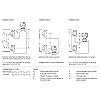
Types of installation for pressure and level measurements (open vessels)
Installation type A
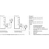
Start-of-scale:
pMA = ÏFL · g · HU - Ïoil · g · H1
Full-scale:
pME = ÏFL · g · HO - Ïoil · g · H1
Installation type B
Start-of-scale:
pMA = ÏFL · g · HU + Ïoil · g · H1
Full-scale:
pME = ÏFL · g · HO + Ïoil · g · H1
Legend
pMA
Pressure to be set at start-of-scale
pME
Pressure to be set at end-of-scale
ÏFL
Density of medium in vessel
Ïoil
Density of filling oil in the capillary to the remote seal
g
Local acceleration due to gravity
HU
Minimum level
HO
Maximum level
H1
Distance between vessel flange and pressure transmitter
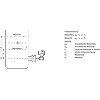
Types of installation for absolute level measurements (closed vessels)
Installation type C1 and C2
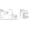
Start-of-scale:
pMA = pSTART + Ïoil · g · H1
Full-scale:
pME = pEND + Ïoil · g · H1
Legend
pMA
Pressure to be set at start-of-scale
pME
Pressure to be set at end-of-scale
pSTART
Pressure at start-of-scale
pEND
Pressure at end-of-scale
Ïoil
Density of filling oil in the capillary to the remote seal
g
Local acceleration due to gravity
H1
Distance between vessel flange and pressure transmitter
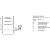
Types of installation for differential pressure and flow measurements
Installation type D
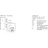
Start-of-scale:
pMA = pSTART - Ïoil · g · HV
Full-scale:
pME = pEND - Ïoil · g · HV
Legend
pMA
Pressure to be set at start-of-scale
pME
Pressure to be set at end-of-scale
pSTART
Pressure at start-of-scale
pEND
Pressure at end-of-scale
Ïoil
Density of filling oil in the capillary to the remote seal
g
Local acceleration due to gravity
HV
Distance between spigots
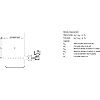
Types of installation for level measurements
Installation type E
Start-of-scale:
pMA = pFL · g · HU - Ïoil · g · HV
Full-scale:
pME = pFL · g · HO - Ïoil · g · HV
Legend
pMA
Pressure to be set at start-of-scale
pME
Pressure to be set at end-of-scale
pFL
Density of medium in vessel
Ïoil
Density of filling oil in the capillary to the remote seal
g
Local acceleration due to gravity
HU
Minimum level
HO
Maximum level
HV
Distance between spigots
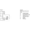
Installation types G, H and J
Start-of-scale:
pMA = pFL · g · HU - Ïoil · g · HV
Full-scale:
pME = pFL · g · HO - Ïoil · g · HV
Legend
pMA
Pressure to be set at start-of-scale
pME
Pressure to be set at end-of-scale
pFL
Density of medium in vessel
Ïoil
Density of filling oil in the capillary to the remote seal
g
Local acceleration due to gravity
HU
Minimum level
HO
Maximum level
HV
Distance between spigots
Measuring setups without remote seals
The following types of installation are used to measure level, separation level and density in open and closed vessels without the application of remote seals.
Notes
When measuring separation layers, ensure that:
- The separation layer is positioned between the two spigots.
- The level in the vessel must always be above the top spigot.
When measuring density, ensure that:
At the end of this section is a questionnaire which you can use is used for hydrostatic level measurements, e.g. for measuring the level in steam boilers, steam drums, condensation vessels, etc.
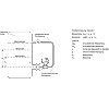
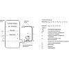
Setup for pressure transmitters for differential pressure, flange mounting (open vessels)
Level measurement
Start-of-scale:
pMA = Ï · g · HU
Full-scale:
pME = Ï · g · HO
Legend
pMA
Pressure to be set at start-of-scale
pME
Pressure to be set at end-of-scale
Ï
Density of medium in vessel
g
Local acceleration due to gravity
HU
Minimum level
HO
Maximum level
Separation layer measurement
Start-of-scale:
pMA = g · (HU · Ï1 + (HO - HU) · Ï2)
Full-scale:
pME = Ï1 · g · HO
Legend
pMA
Pressure to be set at start-of-scale
pME
Pressure to be set at end-of-scale
Ï1
Density of the heavier liquid
Ï2
Density of the lighter liquid
g
Local acceleration due to gravity
HU
Minimum level
HO
Maximum level
Density measurement
Start-of-scale:
pMA = ÏMIN · g · HO
Full-scale:
pME = ÏMAX · g · HO
Legend
pMA
Pressure to be set at start-of-scale
pME
Pressure to be set at end-of-scale
ÏMIN
Minimum density of medium in vessel
ÏMAX
Maximum density of medium in vessel
g
Local acceleration due to gravity
HO
Maximum level
Setup for pressure transmitters for differential pressure, flange mounting (closed vessels)
Level measurement, version 1
Start-of-scale:
ΔpMA = Ï · g · HU
Full-scale:
ΔpME = Ï · g · HO
Legend
ΔpMA
Pressure to be set at start-of-scale
ΔpME
Pressure to be set at end-of-scale
Ï
Density of medium in vessel
g
Local acceleration due to gravity
HU
Minimum level
HO
Maximum level
Level measurement, version 2
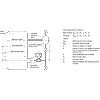
Start-of-scale:
pMA = g · (HU · Ï - HV · Ï′)
Full-scale:
pME = g · (HO · Ï - HV · Ï′)
Legend
pMA
Pressure to be set at start-of-scale
pME
Pressure to be set at end-of-scale
Ï
Density of medium in vessel
Ï′
Density of liquid in the negative pressure line, corresponding to the temperature existing there
g
Local acceleration due to gravity
HU
Minimum level
HO
Maximum level
HV
Distance between spigots
Separation layer measurement
Start-of-scale:
ΔpMA = g · (HU · Ï1 + (HO-HU) · Ï2 - HV · Ï′2)
Full-scale:
ΔpMA = g · (HO · Ï1 - HV · Ï′2)
Legend
pMA
Pressure to be set at start-of-scale
pME
Pressure to be set at end-of-scale
Ï1
Density of heavier liquid with separation layer in vessel
Ï2
Density of lighter liquid with separation layer in vessel
Ï′2
Density of liquid in the negative pressure line for separation layer measurement, corresponding to the temperature existing there
g
Local acceleration due to gravity
HU
Minimum level
HO
Maximum level
HV
Distance between spigots