
- Каталог оборудования Siemens
- Каталог продуктов Siemens Industry
- Приводная техника
- Техника автоматизации
- Системы автоматизации
- Системы визуализации SIMATIC HMI
- Системы идентификации
- Промышленные коммуникации SIMATIC NET
- Промышленные аппараты управления SIRIUS
- Промышленные информационные технологии
- Управление на базе РС
- Системы управления процессом
- Контрольно-измерительные приборы
- Измерительные преобразователи для давления
- Приборы измерения температуры SITRANS T
- Расходомеры
- Уровнемеры
- Позиционеры
- Устройство для защиты и пуска двигателей SIMOCODE-DP
- Сигнализаторы сбоев в промышленном процессе
- Аппаратные ПИД-регуляторы SIPART
- Встраиваемые самописцы и индикаторы
- Технологии взвешивания
- Дополнительные компоненты
- Коммуникации и программное обеспечение
- Directives
- Анализаторы процесса
- Блоки питания SITOP
- Продукты для специальных требований
- Energy
- Автоматизация и безопасность зданий
- Низковольтная коммутационная техника
- Технология безопасности
- Системные решения и продукты для отраслей
- Сервис
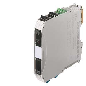
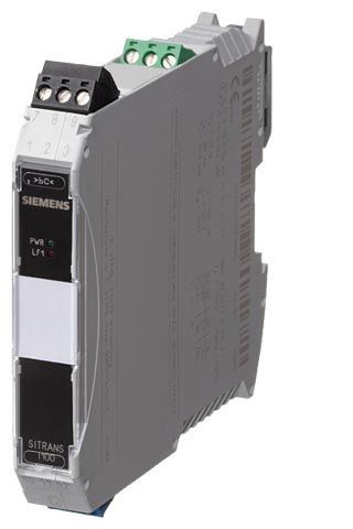
SITRANS I100, isolating power supply
- Заказные данные (1)
- Аксессуары (2)
- Информационные материалы
Информационные материалы
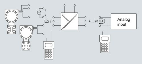
Analog input 0/4 to 20 mA
The isolating power supplies are used for the intrinsically safe operation of 2- and 3-wire transmitters and for connecting to intrinsically safe mA sources.
The 2- and 3-wire transmitters are supplied with auxiliary power from the transmitter supply unit.
For 2-wire transmitters the isolators transfer the HART communication signal bidirectionally.
Дизайн
The HART isolating power supply is comprised of a compact plastic enclosure (IP30) and is equipped with push-in screw terminals.
On the front are a green LED for indicating the power supply status and a red LED for signaling errors.
The auxiliary power supply can be connected individually using push-in screw terminals or jointly for up to 40 units using pac-Bus.
STRANS I100 isolating power supply, function block diagram
Чертеж

SITRANS I100 isolating power supply with HART, dimensions in mm (inch)
Особенности
- Active output 0/4 to 20 mA
- Suitable for 2-, 3-wire transmitters, 2-wire HART transmitters and mA sources
- Intrinsically safe input [Ex ia] IIC
- Electrical isolation between input, output and auxiliary power
- Open-circuit and short-circuit monitoring and messaging for input and output (can be switched off)
- Installation possible in Zone 2 and Div. 2
- Can be used up to SIL 2 (IEC 61508)
Zones
0
1
2
20
21
22
Ex i interfaces
X
X
X
X
X
X
Installation in
X
X
Схема подключения
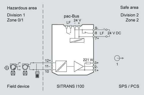
SITRANS I100 isolating power supply with HART, connection diagram
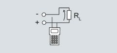
SITRANS I100 isolating power supply with HART, output configuration
Технические данные
SITRANS I100 Isolating Power Supplies with HART
Ex i input
Input signal
0/4 ... 20 mA with HART
Functional range
0 ... 24 mA
Max. input current for mA sources
50 mA
Transmitter supply voltage
≥ 16 V at 20 mA (for 2-, 3-wire)
Supply voltage residual ripple
≤ 25 mVeff
No-load voltage
≤ 26 V
Short-circuit current
≤ 35 mA
Input resistance (AC impedance HART)
≈ 500 Ω
Input resistance for mA sources
30 Ω
Communication signal (on 2-wire transmitters)
Bidirectional HART transmission, 0.5 kHz ... 30 kHz
Output
Output signal
0/4 ... 20 mA with HART
Load resistance RL
0 ... 600 Ω (terminal 1+/2-)
0 ... 379 Ω (terminal 3+/2)
(with internal 221 Ω resistance for HART)
Residual ripple
≤ 40 μAeff
No-load voltage
≤ 15.5 V
Communication signal
Bidirectional HART transmission, 0.5 kHz ... 30 kHz
Response time (10% ... 90%)
≤ 25 ms
Transmission characteristics
Input/output1:1
(0 ... 20 mA --> 0 ... 20 mA, 4 ... 20 mA --> 4 ... 20 mA)Measuring accuracy
Accuracy, typical data expressed as % of calibrated span at UN, 23 °C
Linearity error
≤ 0.1%
Offset error
≤ 0.1%
Temperature influence
≤ 0.1%/10 K
Power supply effect within voltage range
≤ 0.01%
Load resistance effect
≤ 0.02%
Rated conditions
Degree of protection of enclosure
IP30
Degree of protection of terminals
IP20
Ambient conditions
- Ambient temperature
-20 °C ... +60 °C/+70 °C (-4 ... +140/+158 °F)
(see "Operating instructions")- Storage temperature
-40 °C ... +80 °C (-40 ... +176 °F)
- Relative humidity (no condensation)
≤ 95%
Electromagnetic compatibility
Tested under the following standards and regulations: EN 61326-1 Use in the industrial environment
Design
Screw terminals
- One-wire connection
- Rigid
0.2 ... 2.5 mm2 (0.00031 ... 0.0039 in2)
- Flexible
0.2 ... 2.5 mm2 (0.00031 ... 0.0039 in2)
- Flexible with end ferrules (without/with plastic ferrule)
0.25 ... 2.5 mm2 (0.00039 ... 0.0039 in2)
- Two-wire connection
- Rigid
0.2 ... 1 mm2 (0.00031 ... 0.00155 in2)
- Flexible
0.2 ... 1.5 mm2 (0.00031 ... 0.0023 in2)
- Flexible with end ferrules
0.25 ... 1 mm2 (0.00039 ... 0.00155 in2)
Weight
Approx. 160 g (0.35 lb)
Type of installation
On DIN rail according to EN 50022 (NS35/15; NS35/7.5)
Mounting position
Vertical or horizontal
Enclosure material
PA 6.6
Fire protecting class (UL-94)
V0
Auxiliary power
Rated voltage UN
24 V DC
Voltage range
18 ... 31.2 V
Residual ripple within voltage range
≤ 3.6 VSS
Rated current (UN, 20 mA)
70 mA
Power consumption (UN, 20 mA)
1.7 W
Power loss (at UN, RL = 250 Ω)
1.3 W
Operation indicator
Green "PWR" LED
Reverse polarity protection
Yes
Undervoltage monitoring
Yes (no faulty module/output states)
Electrical isolation
- Test voltage according to EN 60079-11
- Ex i input to output
1.5 kV AC
- Ex i input to auxiliary power
1.5 kV AC
- Ex i input to Error contact
1.5 kV AC
- Test voltage according to EN 50178
- Output to auxiliary power
350 V AC
- Error contact to auxiliary power and output
350 V AC
Error detection Ex i input
- Open circuit
< 2 mA
- Short-circuit
> 22 mA
- Output characteristics
= Input signal
- Output current at IE = 0
IA = 0 mA
Error detection output
- Open circuit
< 2 mA
Error messaging Ex i input/output
- Settings (LF switch)
Activated/deactivated
- Error indication
LED red "LF"
Error messaging and power supply failure
- Contact (30 V/100 mA), closed to ground in case of error
- pac-Bus, floating contact (30 V/100 mA)
Certificates and approvals
Explosion protection ATEX
- EC type-examination certificate
DMT 03 ATEX E 010 X
- Degree of protection
II 3 (1) G Ex nA nC [ia] IIC T4
II (1) D [Ex iaD]
Installation
In Zone 2, Div. 2 and in the safe area
Other approvals
USA (FM)
Canada (CSA)
Shipping (DNV)
Safety specifications (CENELEC)
- Max. voltage Uo
27 V
- Max. current Io
88 mA
- Max. power Po
576 mW
- Max. connectable capacitance Co for IIC/IIB
90 nF/705 nF
- Max. connectable inductance Lo for IIC/IIB
2.3 mH/14 mH
- Internal capacitance Ci and inductance Li
Negligible
- Insulation voltage Um
253 V
- When connecting mA sources:
- Max. output voltage Uo
4.1 V
- Max. connectable voltage Ui
30 V
- Max. connectable current Ii
100 mA
- Internal capacitance Ci and inductance Li
Negligible
- Additional information and value combinations
See Certifications