
- Каталог оборудования Siemens
- Каталог продуктов Siemens Industry
- Приводная техника
- Техника автоматизации
- Системы автоматизации
- Системы визуализации SIMATIC HMI
- Системы идентификации
- Промышленные коммуникации SIMATIC NET
- Промышленные аппараты управления SIRIUS
- Промышленные информационные технологии
- Управление на базе РС
- Системы управления процессом
- Контрольно-измерительные приборы
- Анализаторы процесса
- Блоки питания SITOP
- Продукты для специальных требований
- Модули с расширенным температурным диапазоном SIPLUS
- Системы телеметрии
- IO Systems for heating units
- Automatic door controls
- Condition monitoring systems
- Time synchronization
- Energy
- Автоматизация и безопасность зданий
- Низковольтная коммутационная техника
- Технология безопасности
- Системные решения и продукты для отраслей
- Сервис
SIPLUS smart
- Заказные данные (1)
- Информационные материалы
Информационные материалы
Замечание:
Продукты SIPLUS extreme строятся на базе стандартных промышленных продуктов Siemens. Приведенная ниже информация дополняет описания стандартных продуктов специфичными данными продуктов SIPLUS extreme.
SIPLUS smart 10 A
Заказной номер
6AG1 334-2BA01-4AA0
Заказной номер базового модуля
6EP1 334-2BA01
Диапазон рабочих температур
0 ... +60 °C
Защитные покрытия
Печатных плат и электронных компонентов
Технические данные
Соответствуют техническим данным базового модуля за исключением допустимых условий эксплуатации
Условия эксплуатации
Относительная влажность
5 ... 100%, допускается появление конденсата
Биологически активные вещества
По EN 60721-3-3, класс 3B2: плесень, споры грибка (исключая живые организмы)
Химически активные вещества
По EN 60721-3-3, класс 3C4, включая соленый туман, и уровни сложности G1; G2; G3; GX 1)2) по ISA–S71.04
Механически активные вещества
По EN 60721‑3‑3, класс 3S4, включая токопроводящий песок и пыль 2)
Атмосферное давление (зависит от верхней границы допустимого диапазона рабочих температур)
1080 ... 795 гПа (-1000 ... +2000 м)
во всем диапазоне рабочих температур795 ... 658 гПа (+2000 ... +3500 м)
со снижением верхней границы на 10 K658 ... 540 гПа (+3500 ... +5000 м)
со снижением верхней границы на 20 K1) ISA-S71.04 уровень сложности GX: длительно: SO2 < 4.8 мг/м3; H2S < 9.9 мг/м3; Cl < 0.2 мг/м3; HCl < 0.66 мг/м3; HF < 0.12 мг/м3; NH < 49 мг/м3; O3 < 0.1 мг/м3; NOX < 5.2 мг/м3
В течение 30 минут в сутки: SO2 < 17.8 мг/м3; H2S < 49.7 мг/м3; Cl < 1.0 мг/м3; HCl < 3.3 мг/м3; HF < 2.4 мг/м3; NH < 247 мг/м3; O3 < 1.0 мг/м3; NOX < 10.4 мг/м32) При эксплуатации в атмосфере с содержанием коррозивных газов на незадействованные интерфейсы должны устанавливаться включенные в комплект поставки защитные заглушки!
Техническую документацию по продуктам SIPLUS можно найти по ссылке:
http://www.siemens.de/siplus-extremeОбласть применения
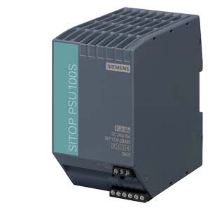
Инновационный, однофазный блок питания универсального назначения для применения во всех регионах мира. Имеет сертификаты UL, CSA и GL, соответствует требованиям директивы EU № 94/9/EC (ATEX 100a). Небольшая ширина корпуса, входные перенапряжения до 120% от номинального значения при 45°C, временные перегрузки до 150% от номинального значения выходного тока. Настраиваемый с помощью потенциометра уровень выходного напряжения с вехним пределом до =28 В. Ограничение гармоник во входной цепи в соответствии с требованиями стандарта EN 61000-3-2 (только для модификации 6EP1334-2AB01).
Технические данные
Order number
6EP1332-2BA20
6EP1333-2BA20
6EP1334-2BA20
6EP1336-2BA10
Product
SITOP PSU100S
SITOP PSU100S
SITOP PSU100S
SITOP PSU100S
Power supply, type
24 V/2.5 A
24 V/5 A
24 V/10 A
24 V/20 A
Input
Input
1-phase AC
1-phase AC
1-phase AC
1-phase AC
Supply voltage
● 1 with AC Rated value
120 V
120 V
120 V
120 V
● 2 with AC Rated value
230 V
230 V
230 V
230 V
● Note
Automatic range selection
Automatic range selection
Automatic range selection
Automatic range selection
Input voltage
● 1 with AC
85 ... 132 V
85 ... 132 V
85 ... 132 V
85 ... 132 V
● 2 with AC
170 ... 264 V
170 ... 264 V
170 ... 264 V
176 ... 264 V
Wide-range input
No
No
No
No
Overvoltage resistance
2.3 × Vin rated, 1.3 ms
2.3 × Vin rated, 1.3 ms
2.3 × Vin rated, 1.3 ms
2.3 × Vin rated, 1.3 ms
Mains buffering at Iout rated, min.
20 ms; at Vin = 93/187 V
20 ms; at Vin = 93/187 V
20 ms; at Vin = 93/187 V
20 ms; at Vin = 120/230 V
Rated line frequency
50 ... 60 Hz
50 ... 60 Hz
50 ... 60 Hz
50 ... 60 Hz
Rated line range
47 ... 63 Hz
47 ... 63 Hz
47 ... 63 Hz
47 ... 63 Hz
Input current
● at rated input voltage 120 V
1.25 A
2.34 A
4.49 A
7.5 A
● at rated input voltage 230 V
0.74 A
1.36 A
1.91 A
3.5 A
Switch-on current limiting (+25 °C), max.
33 A
40 A
60 A
11 A
I²t, max.
0.4 A²·s
1 A²·s
5.6 A²·s
10 A²·s
Built-in incoming fuse
T 3,15 A/250 V (not accessible)
T 3,15 A/250 V (not accessible)
T 6.3 A/250 V (not accessible)
T 10 A (not accessible)
Protection in the mains power input (IEC 898)
Recommended miniature circuit breaker: from 3 A characteristic C
Recommended miniature circuit breaker: from 6 A characteristic C
Recommended miniature circuit breaker: from 10 A characteristic C
Recommended miniature circuit breaker: from 10 A characteristic C or circuit-breaker 3RV2411-1JA10 (120 V) or 3RV2411-1FA10 (230 V)
Output
Output
Controlled, isolated DC voltage
Controlled, isolated DC voltage
Controlled, isolated DC voltage
Controlled, isolated DC voltage
Rated voltage Vout DC
24 V
24 V
24 V
24 V
Total tolerance, static ±
3 %
3 %
3 %
3 %
Static mains compensation, approx.
0.1 %
0.1 %
0.1 %
0.5 %
Static load balancing, approx.
1 %
1 %
1 %
1 %
Residual ripple peak-peak, max.
150 mV
150 mV
150 mV
150 mV
Residual ripple peak-peak, typ.
30 mV
30 mV
20 mV
Spikes peak-peak, max. (bandwidth: 20 MHz)
240 mV
240 mV
240 mV
240 mV
Spikes peak-peak, typ. (bandwidth: 20 MHz)
70 mV
140 mV
160 mV
Adjustment range
22.8 ... 28 V
22.8 ... 28 V
22.8 ... 28 V
24 ... 28 V
Product function Output voltage adjustable
Yes
Yes
Yes
Yes
Output voltage setting
via potentiometer
via potentiometer
via potentiometer
via potentiometer; max. 480 W
Status display
Green LED for 24 V OK
Green LED for 24 V OK
Green LED for 24 V OK
Green LED for 24 V OK
Signaling
Relay contact (NO contact, rating 60 V DC/ 0.3 A) for "24 V OK"
Relay contact (NO contact, rating 60 V DC/ 0.3 A) for "24 V OK"
Relay contact (NO contact, rating 60 V DC/ 0.3 A) for "24 V OK"
Relay contact (NO contact, rating 50 V DC/ 0.3 A) for "24 V OK"
On/off behavior
Overshoot of Vout < 3 %
Overshoot of Vout < 3 %
Overshoot of Vout < 3 %
No overshoot of Vout (soft start)
Startup delay, max.
0.3 s
0.3 s
0.3 s
1.5 s
Voltage rise, typ.
15 ms
15 ms
20 ms
50 ms
Voltage increase time of the output voltage maximum
500 ms
Rated current value Iout rated
2.5 A
5 A
10 A
20 A
Current range
0 ... 3 A
0 ... 6 A
0 ... 12 A
0 ... 20 A
● Note
3 A up to +45°C; +60 ... +70 °C: Derating 3%/K
6 A up to +45°C; +60 ... +70 °C: Derating 1.6%/K
12 A up to +45°C; +60 ... +70 °C: Derating 3%/K
24 A up to +45°C; +60 ... +70 °C: Derating 5%/K
Active power supplied typical
60 W
144 W
288 W
480 W
Short-term overload current
● on short-circuiting during the start-up typical
9 A
18 A
32 A
35 A
● at short-circuit during operation typical
9 A
18 A
32 A
35 A
Duration of overloading capability for excess current
● on short-circuiting during the start-up
100 ms
800 ms
1 000 ms
100 ms
● at short-circuit during operation
800 ms
800 ms
1 000 ms
100 ms
Parallel switching for enhanced performance
Yes
Yes
Yes
Yes
Numbers of parallel switchable units for enhanced performance
2
2
2
2
Efficiency
Efficiency at Vout rated, Iout rated, approx.
85 %
88 %
90 %
90 %
Power loss at Vout rated, Iout rated, approx.
10 W
16 W
25 W
53 W
Closed-loop control
Dynamic mains compensation (Vin rated ±15 %), max.
0.3 %
0.3 %
0.3 %
1 %
Dynamic load smoothing (Iout: 50/100/50 %), Uout ± typ.
3 %
Dynamic load smoothing (Iout: 10/90/10 %), Uout ± typ.
5 %
3 %
3 %
Load step setting time 10 to 90%, typ.
1 ms
1 ms
1 ms
Load step setting time 90 to 10%, typ.
1 ms
1 ms
1 ms
Setting time maximum
10 ms
Protection and monitoring
Output overvoltage protection
protection against overvoltage in case of internal fault Vout < 33 V
protection against overvoltage in case of internal fault Vout < 33 V
protection against overvoltage in case of internal fault Vout < 33 V
Yes, according to EN 60950-1
Current limitation
3 ... 3.4 A
6 ... 7.1 A
12 ... 14.6 A
Current limitation, typ.
21 A
Property of the output Short-circuit proof
Yes
Yes
Yes
Yes
Short-circuit protection
Constant current characteristic
Constant current characteristic
Constant current characteristic
Electronic shutdown, automatic restart
Enduring short circuit current RMS value
● maximum
7 A
● typical
3.4 A
7.1 A
14.6 A
Overcurrent overload capability in normal operation
overload capability 150 % Iout rated up to 5 s/min
overload capability 150 % Iout rated up to 5 s/min
overload capability 150 % Iout rated up to 5 s/min
overload capability 150 % Iout rated up to 5 s/min
Overload/short-circuit indicator
-
-
-
-
Safety
Primary/secondary isolation
Yes
Yes
Yes
Yes
Galvanic isolation
Safety extra-low output voltage Uout acc. to EN 60950-1 and EN 50178
Safety extra-low output voltage Uout acc. to EN 60950-1 and EN 50178
Safety extra-low output voltage Uout acc. to EN 60950-1 and EN 50178
Safety extra-low output voltage Uout acc. to EN 60950-1 and EN 50178
Protection class
Class I
Class I
Class I
Class I
Leakage current
● maximum
3.5 mA
3.5 mA
3.5 mA
3.5 mA
● typical
0.4 mA
0.4 mA
0.8 mA
1 mA
CE mark
Yes
Yes
Yes
Yes
UL/CSA approval
Yes
Yes
Yes
Yes
UL/cUL (CSA) approval
cULus-Listed (UL 508, CSA C22.2 No. 107.1), File E197259, cCSAus (CSA C22.2 No. 60950-1, UL 60950-1, UL 1604)
cULus-Listed (UL 508, CSA C22.2 No. 107.1), File E197259, cCSAus (CSA C22.2 No. 60950-1, UL 60950-1, UL 1604)
cULus-Listed (UL 508, CSA C22.2 No. 107.1), File E197259, cCSAus (CSA C22.2 No. 60950-1, UL 60950-1, UL 1604)
cULus-Listed (UL 508, CSA C22.2 No. 107.1), File E197259; in preparation: cCSAus (CSA C22.2 No. 60950-1, UL 60950-1)
Explosion protection
ATEX (EX) II 3G Ex nA nC IIC T4 Gc; cCSAus (CSA C22.2 No. 213-M1987, ANSI/ISA-12.12.01-2007) Class I, Div. 2, Group ABCD, T4
ATEX (EX) II 3G Ex nA nC IIC T4 Gc; cCSAus (CSA C22.2 No. 213-M1987, ANSI/ISA-12.12.01-2007) Class I, Div. 2, Group ABCD, T4
ATEX (EX) II 3G Ex nA nC IIC T4 Gc; cCSAus (CSA C22.2 No. 213-M1987, ANSI/ISA-12.12.01-2007) Class I, Div. 2, Group ABCD, T4
ATEX (EX) II 3G Ex nA nC IIC T4 Gc; cCSAus (CSA C22.2 No. 213, ANSI/ISA-12.12.01) Class I, Div. 2, Group ABCD, T4
Certificate of suitability IECEx
No
No
No
No
Certificate of suitability NEC Class 2
No
No
No
No
FM approval
-
-
-
-
CB approval
Yes
Yes
Yes
Yes
Marine approval
GL, BV
GL, BV
GL, BV
GL
Degree of protection (EN 60529)
IP20
IP20
IP20
IP20
EMC
Emitted interference
EN 55022 Class B
EN 55022 Class B
EN 55022 Class B
EN 55022 Class B
Supply harmonics limitation
not applicable
EN 61000-3-2
EN 61000-3-2
EN 61000-3-2
Noise immunity
EN 61000-6-2
EN 61000-6-2
EN 61000-6-2
EN 61000-6-2
Operating data
Ambient temperature
● during operation
-25 ... +70 °C
-25 ... +70 °C
-25 ... +70 °C
0 ... 70 °C
— Note
with natural convection
with natural convection
with natural convection
with natural convection
● during transport
-40 ... +85 °C
-40 ... +85 °C
-40 ... +85 °C
-40 ... +85 °C
● during storage
-40 ... +85 °C
-40 ... +85 °C
-40 ... +85 °C
-40 ... +85 °C
Humidity class according to EN 60721
Climate class 3K3, no condensation
Climate class 3K3, no condensation
Climate class 3K3, no condensation
Climate class 3K3, no condensation
Mechanics
Connection technology
screw-type terminals
screw-type terminals
screw-type terminals
screw-type terminals
Connections
● Supply input
L, N, PE: 1 screw terminal each for 0.5 ... 2.5 mm² single-core/finely stranded
L, N, PE: 1 screw terminal each for 0.5 ... 2.5 mm² single-core/finely stranded
L, N, PE: 1 screw terminal each for 0.5 ... 2.5 mm² single-core/finely stranded
L1, N, PE: 1 screw terminal each for 0.2 ... 4 mm² single-core/finely stranded
● Output
+, -: 2 screw terminals each for 0.5 ... 2.5 mm²
+, -: 2 screw terminals each for 0.5 ... 2.5 mm²
+, -: 2 screw terminals each for 0.5 ... 2.5 mm²
+, -: 2 screw terminals each for 0.2 ... 4 mm²
● Auxiliary
Alarm signals: 2 screw terminals for 0.5 ... 2.5 mm²
Alarm signals: 2 screw terminals for 0.5 ... 2.5 mm²
Alarm signals: 2 screw terminals for 0.5 ... 2.5 mm²
13, 14 (alarm signal): 1 screw terminal each for 0.14 ... 1.5 mm²
Width of the enclosure
32.5 mm
50 mm
70 mm
115 mm
Height of the enclosure
125 mm
125 mm
125 mm
145 mm
Depth of the enclosure
120 mm
120 mm
120 mm
150 mm
Weight, approx.
0.32 kg
0.5 kg
0.8 kg
2.4 kg
Product property of the enclosure housing for side-by-side mounting
Yes
Yes
Yes
Yes
Installation
Snaps onto DIN rail EN 60715 35x7.5/15
Snaps onto DIN rail EN 60715 35x7.5/15
Snaps onto DIN rail EN 60715 35x7.5/15
Snaps onto DIN rail EN 60715 35x7.5/15
Electrical accessories
Buffer module
Buffer module
Buffer module
Buffer module
Mechanical accessories
Device identification label 20 mm × 7 mm, pastel-turpuoise 3RT1900-1SB20
Other information
Specifications at rated input voltage and ambient temperature +25 °C (unless otherwise specified)
Specifications at rated input voltage and ambient temperature +25 °C (unless otherwise specified)
Specifications at rated input voltage and ambient temperature +25 °C (unless otherwise specified)
Specifications at rated input voltage and ambient temperature +25 °C (unless otherwise specified)