
- Каталог оборудования Siemens
- Каталог продуктов Siemens Industry
- Приводная техника
- Техника автоматизации
- Системы автоматизации
- Системы визуализации SIMATIC HMI
- Системы идентификации
- Промышленные коммуникации SIMATIC NET
- Промышленные аппараты управления SIRIUS
- Промышленные информационные технологии
- Управление на базе РС
- Системы управления процессом
- Контрольно-измерительные приборы
- Анализаторы процесса
- Блоки питания SITOP
- Продукты для специальных требований
- Модули с расширенным температурным диапазоном SIPLUS
- Промышленные системы автоматизации SIMATIC
- Программируемые контроллеры
- Распределенная периферия SIMATIC ET200
- SIPLUS ET 200 systems for the control cabinet
- SIPLUS ET 200SP
- Интерфейсные модули SIPLUS
- SIPLUS extreme RAIL interface modules
- Модули ввода-вывода SIPLUS
- Модули ввода дискретных сигналов SIPLUS
- Модули вывода дискретных сигналов SIPLUS
- Модули ввода аналоговых сигналов SIPLUS
- Модули вывода аналоговых сигналов SIPLUS
- SIPLUS technology modules
- SIPLUS Communication
- SIPLUS F модули
- SIPLUS extreme RAIL digital input modules
- SIPLUS extreme RAIL digital output modules
- SIPLUS extreme RAIL analog input modules
- SIPLUS extreme RAIL analog output modules
- SIPLUS extreme RAIL Communication modules
- Базовые блоки SIPLUS
- SIPLUS BusAdapter
- SIPLUS extreme RAIL BaseUnits
- SIPLUS extreme RAIL BusAdapter
- SIPLUS ET 200S
- SIPLUS ET 200MP
- ET 200M
- SIPLUS ET 200SP
- Компоненты SIPLUS PROFIBUS для ET 200
- SIPLUS ET 200 systems for the control cabinet
- Система управления перемещением SIMOTION
- Распределенные системы управления
- Системы оперативного управления и мониторинга
- Промышленные коммуникации
- Аппаратура управления
- Блоки питания
- Дополнения SIPLUS
- Промышленные системы автоматизации SIMATIC
- Системы телеметрии
- IO Systems for heating units
- Automatic door controls
- Condition monitoring systems
- Time synchronization
- Модули с расширенным температурным диапазоном SIPLUS
- Energy
- Автоматизация и безопасность зданий
- Низковольтная коммутационная техника
- Технология безопасности
- Системные решения и продукты для отраслей
- Сервис
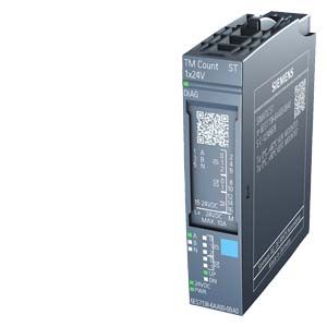
SIPLUS TM Count 1x24V counter module
- Заказные данные (1)
- Аксессуары (15)
- Информационные материалы
Информационные материалы
Technical properties
- Counter module for ET 200SP
- Interfaces:
- 24 V encoder signals A, B and N from P, M or push-pull-switching encoders and sensors
- 24 V encoder supply output, short-circuit proof
- 3 digital inputs for controlling the count operation, for saving or for setting the count value
- 2 digital outputs for fast reactions regardless of the counter status or measured value
- Counting frequency 200 kHz (800 kHz with quadruple evaluation)
- Counting range: +/- 31 bits
- Measurement function
- Parameterizable hardware interrupts
- Parameterizable input filters for suppressing interferences at sensor and digital inputs
Supported types of encoders/signals
- 24 V incremental encoder with and without signal N
- 24 V pulse encoder with direction signal
- 24 V pulse encoder without direction signal
- 24 V pulse encoder for pulse up and down respectively
Supported system functions
- Isochronous mode
- Firmware update
- Identification data I&M
Note
SIPLUS extreme products are based on SIMATIC standard products. The contents listed here were taken from the respective standard products. SIPLUS extreme specific information was added.
Область применения
In particular, the TM Count 1x24V counter module detects high-speed signals with high frequencies and returns the counter reading and the current speed to the control. The counter control ensures a precise counter result and rapid response in the system via integrated digital input and output signals. Comprehensive parameterization options provide optimum adaptation to the task at hand and reduce control load.
Дизайн
Usable BaseUnits
Standard BaseUnits type A0 of the ET 200SP are available for connection. The individual signals of the counter module are connected to the appropriate terminals.
A light BaseUnit opens a new load group. The supply voltage must be fed in via this BaseUnit. The first BaseUnit next to the interface module must always be a light BaseUnit.
A dark BaseUnit forwards the power supply of the adjacent light BaseUnit on the left via self-assembling voltage buses. A new infeed is therefore only required on the next light BaseUnit to the right.
All variants that correspond to BaseUnit type A0 can be used as BaseUnits.
System-integrated shielded connection
For space-saving and EMC technically optimized connection of cable shields, a shield connection is available that is quick and easy to mount. This consists of one shield connection element that can be plugged onto the BaseUnit and one shield terminal for each module. The low-impedance connection to functional ground (DIN rail) is carried out by the user and requires no additional wiring.
Accessories (not included in the scope of supply of the module)
- Labeling strips
- Color-coding labels
- Reference identification labels
- Shield connection
Технические данные
Order number
6AG1138-6AA00-2BA0
SIPLUS ET 200SP TM COUNT 1X24V
General information
Product type designation
TM Count 1x24V
Product function
● I&M data
Yes; I&M0 to I&M3
Engineering with
● STEP 7 TIA Portal configurable/integrated as of version
V13 / V13
● STEP 7 configurable/integrated as of version
V5.5 SP3 / V5.5 SP4
● PROFIBUS as of GSD version/GSD revision
GSD Revision 5
● PROFINET as of GSD version/GSD revision
GSDML V2.3
Supply voltage
Load voltage L+
● Rated value (DC)
24 V
● permissible range, lower limit (DC)
19.2 V
● permissible range, upper limit (DC)
28.8 V
● Reverse polarity protection
Yes
Input current
Current consumption, max.
60 mA; without load
Encoder supply
Number of outputs
1
24 V encoder supply
● 24 V
Yes; L+ (-0.8 V)
● Short-circuit protection
Yes
● Output current, max.
300 mA
Digital inputs
Number of digital inputs
3
Digital inputs, parameterizable
Yes
Input characteristic curve in accordance with IEC 61131, type 3
Yes
Digital input functions, parameterizable
● Gate start/stop
Yes
● Capture
Yes
● Synchronization
Yes
● Freely usable digital input
Yes
Input voltage
● Rated value (DC)
24 V
● for signal "0"
-30 to +5V
● for signal "1"
+11 to +30V
● permissible voltage at input, min.
-30 V
● permissible voltage at input, max.
30 V
Input current
● for signal "1", typ.
2.5 mA
Input delay (for rated value of input voltage)
for standard inputs
— parameterizable
Yes; none / 0.05 / 0.1 / 0.4 / 0.8 / 1.6 / 3.2 / 12.8 / 20 ms
— at "0" to "1", min.
6 µs; for parameterization "none"
— at "1" to "0", min.
6 µs; for parameterization "none"
for counter/technological functions
— parameterizable
Yes
Cable length
● shielded, max.
1 000 m
● unshielded, max.
600 m
Digital outputs
Type of digital output
Transistor
Number of digital outputs
2
Digital outputs, parameterizable
Yes
Short-circuit protection
Yes; electronic/thermal
Limitation of inductive shutdown voltage to
L+ (-33 V)
Controlling a digital input
Yes
Digital output functions, parameterizable
● Switching tripped by comparison values
Yes
● Freely usable digital output
Yes
Switching capacity of the outputs
● with resistive load, max.
0.5 A; Per digital output
● on lamp load, max.
5 W
Load resistance range
● lower limit
48 Ω
● upper limit
12 kΩ
Output voltage
● for signal "1", min.
23.2 V; L+ (-0.8 V)
Output current
● for signal "1" rated value
0.5 A; Per digital output
● for signal "0" residual current, max.
0.5 mA
Output delay with resistive load
● "0" to "1", max.
50 µs
● "1" to "0", max.
50 µs
Switching frequency
● with resistive load, max.
10 kHz
● with inductive load, max.
0.5 Hz; Acc. to IEC 60947-5-1, DC-13; observe derating curve
● on lamp load, max.
10 Hz
Total current of the outputs
● Current per module, max.
1 A
Cable length
● shielded, max.
1 000 m
● unshielded, max.
600 m
Encoder
Connectable encoders
● 2-wire sensor
Yes
— permissible quiescent current (2-wire sensor), max.
1.5 mA
Encoder signals, incremental encoder (asymmetrical)
● Input voltage
24 V
● Input frequency, max.
200 kHz
● Counting frequency, max.
800 kHz; with quadruple evaluation
● Cable length, shielded, max.
600 m; depending on input frequency, encoder and cable quality; max. 50 m at 200 kHz
● Signal filter, parameterizable
Yes
● Incremental encoder with A/B tracks, 90° phase offset
Yes
● Incremental encoder with A/B tracks, 90° phase offset and zero track
Yes
● Pulse encoder
Yes
● Pulse encoder with direction
Yes
● Pulse encoder with one impulse signal per count direction
Yes
Encoder signal 24 V
— permissible voltage at input, min.
-30 V
— permissible voltage at input, max.
30 V
Interface types
● Input characteristic curve in accordance with IEC 61131, type 3
Yes
● Source/sink input
Yes
Isochronous mode
Isochronous operation (application synchronized up to terminal)
Yes
Interrupts/diagnostics/status information
Substitute values connectable
Yes; Parameterizable
Alarms
● Diagnostic alarm
Yes
● Hardware interrupt
Yes
Diagnostic messages
● Monitoring the supply voltage
Yes
● Wire-break
Yes
● Short-circuit
Yes
● A/B transition error at incremental encoder
Yes
● Group error
Yes
Diagnostics indication LED
● Monitoring of the supply voltage (PWR-LED)
Yes; green PWR LED
● for module diagnostics
Yes; green/red DIAG LED
● Status indicator backward counting (green)
Yes
● Status indicator forward counting (green)
Yes
Integrated Functions
Number of counters
1
Counting frequency (counter) max.
800 kHz; with quadruple evaluation
Counting functions
● Can be used with TO High_Speed_Counter
Yes
● Continuous counting
Yes
● Counter response parameterizable
Yes
● Hardware gate via digital input
Yes
● Software gate
Yes
● Event-controlled stop
Yes
● Synchronization via digital input
Yes
● Counting range, parameterizable
Yes
Comparator
— Number of comparators
2
— Direction dependency
Yes
— Can be changed from user program
Yes
Position detection
● Incremental acquisition
Yes
● Suitable for S7-1500 Motion Control
Yes
Measuring functions
● Measuring time, parameterizable
Yes
● Dynamic measurement period adjustment
Yes
● Number of thresholds, parameterizable
2
Measuring range
— Frequency measurement, min.
0.04 Hz
— Frequency measurement, max.
800 kHz
— Cycle duration measurement, min.
1.25 µs
— Cycle duration measurement, max.
25 s
Accuracy
— Frequency measurement
100 ppm; depending on measuring interval and signal evaluation
— Cycle duration measurement
100 ppm; depending on measuring interval and signal evaluation
— Velocity measurement
100 ppm; depending on measuring interval and signal evaluation
Potential separation
Potential separation channels
● between the channels and backplane bus
Yes
Isolation
Isolation tested with
707 V DC (type test)
Ambient conditions
Ambient temperature during operation
● horizontal installation, min.
-40 °C; = Tmin; Startup @ -25 °C
● horizontal installation, max.
60 °C; = Tmax
Extended ambient conditions
● relative to ambient temperature-atmospheric pressure-installation altitude
Tmin ... Tmax at 1080 hPa ... 795 hPa (-1000 m ... +2000 m) // Tmin ... (Tmax - 10K) at 795 hPa ... 658 hPa (+2000 m ... +3500 m) // Tmin ... (Tmax - 20K) at 658 hPa ... 540 hPa (+3500 m ... +5000 m)
Relative humidity
— With condensation, tested in accordance with IEC 60068-2-38, max.
100 %; RH incl. condensation / frost (no commissioning in bedewed state), horizontal installation
Resistance
— against biologically active substances / conformity with EN 60721-3-3
Yes; Class 3B2 mold, fungus and dry rot spores (with the exception of fauna). The supplied connector covers must remain on the unused interfaces during operation!
— against chemically active substances / conformity with EN 60721-3-3
Yes; Class 3C4 (RH < 75%) incl. salt spray according to EN 60068-2-52 (degree of severity 3). The supplied connector covers must remain on the unused interfaces during operation!
— against mechanically active substances / conformity with EN 60721-3-3
Yes; Class 3S4 incl. sand, dust. The supplied connector covers must remain on the unused interfaces during operation!
Dimensions
Width
15 mm
Weights
Weight, approx.
45 g