
- Каталог оборудования Siemens
- Каталог продуктов Siemens Industry
- Приводная техника
- Преобразователи
- Двигатели переменного тока
- Generators
- Мотор-редукторы
- Flender Gear Units
- Couplings
- Инструментальное программное обеспечение
- Дополнительные компоненты
- Техника автоматизации
- Energy
- Автоматизация и безопасность зданий
- Низковольтная коммутационная техника
- Технология безопасности
- Системные решения и продукты для отраслей
- Сервис
- Приводная техника
Ordering and technology
- Заказные данные (86)
- Аксессуары (27)
- Информационные материалы
Функции
Operator control and visualization with AOP30

An AOP30 Advanced Operator Panel is located in the cabinet door of the converter cabinets for operation, monitoring and commissioning tasks.
The AOP30's two-stage safety concept prevents unintentional or unauthorized changes to settings. Operation of the drive from the operator panel can be disabled using the keyboard lock so that only parameter values and process variables can be displayed on the operating panel. The default setting of the OFF key is "activated", however this can be changed by the customer to "deactivated". A password can be used to prevent the unauthorized modification of the DC converter parameters.
The user is guided by interactive menus through the drive-commissioning screens. Only 5 parameters (which can be found on the motor rating plate and the line supply data) have to be entered on the AOP30 when commissioning the system for the first time. The closed-loop control is then optimized automatically to adapt the converter to the motor.
The operator panel languages German, English and Chinese can be used without any additional memory card. French, Italian, Spanish and Russian are available on the Control Unit memory card (option). The actual unit firmware including languages can be downloaded free of charge from the Internet under the following link: http://support.automation.siemens.com/WW/view/en/38157755/133100
Communication


The units are equipped as standard with PROFIBUS - the industry standard. As a consequence, the converters can be simply and quickly integrated into the TIA environment. PROFINET is available as option. It goes without saying that communications can be established on the drive to higher-level control systems via the fieldbus. This means that using the STARTER commissioning tool, the drives can be monitored and diagnosed from a central location.
In addition to the communication interfaces, naturally there are many digital and analog inputs/outputs available; these can be used to control the converter or to output parameter values for diagnostics. The inputs and outputs are quickly and easily connected via the control terminal strip.
Control terminal strip TMC
The Terminal Module Cabinet (TMC) is located in the lower section of the cabinet, so that all of the digital and analog inputs/outputs can be quickly and simply connected. The installation space has been selected so that it is guaranteed that they are spatially separated from the power cables. Not only this, when retrofitting, the length of the existing signal cables are generally sufficient so that the signal terminals can be used. The digital input/outputs are connected via interface relays in order to guarantee operational safety and reliability. In addition to the inputs/outputs and the incremental encoder interface, optionally the tachometer connection can be routed to the control terminal strip.
Note:
A detailed terminal assignment is provided in the Section, Assignment of terminals and connectors.
Control terminal strip
Terminals for the motor fan
The basic version already includes the power supply for the motor fan. The connections are protected using a motor protection circuit breaker. The setting range of the motor protection circuit breaker must be assigned as option (W20 to W41). As option, the feeder for the motor fan can be omitted or extended by a second motor fan feeder. The feeders are switched using a contactor, which is automatically controlled from the internal sequence control of the SINAMICS DC MASTER.
Terminals for the auxiliary supply
The basic version of the drive cabinet assumes that there is an auxiliary power supply of 400 V 3 AC, 50 Hz from a grounded line supply (TN or TT supply system). The power supply is also used to supply the field and the motor fan. Optionally, other supply voltages and a line frequency of 60 Hz can be selected. It also goes without saying that an option can be selected for an internal auxiliary power supply.
Dependent on the selected options, other terminals are available, for example for the cabinet anti-condensation heating. Data regarding the terminal assignment and the connection options are provided in the description of the relevant option.
For the power connections, the maximum connection cross-sections and the number of cables that can be connected are specified in the technical data.
Closed-loop control functions
Function
Description
Functions of the closed-loop control in the armature circuit
Speed setpoint
The source of the speed setpoint and additional setpoints can be freely selected by making the appropriate parameter settings:
- Entered using analog values 0 to ± 10 V, 0 to ± 20 mA, 4 to 20 mA
- Entered via the fieldbus interface PROFIBUS, Ethernet interface for PROFINET (optional)
- Via the integrated motorized potentiometer
- Via binectors with the functions: Fixed setpoint, jogging, crawl
- Entered via serial interfaces of the SINAMICS DC MASTER
- Entered via supplementary modules
- The scaling is realized so that 100 % setpoint (formed from the main setpoint and supplementary setpoints) corresponds to the max. motor speed.
- The setpoint can be limited to a min. and max. value via a parameter or connector. Further, additional points are provided in the firmware e.g. in order to be able to enter supplementary setpoints before or after the ramp-function generator. The "setpoint enable function" can be selected using a binector. After a parameterizable filter function (PT1 element), the summed setpoint is transferred to the setpoint input of the speed controller. In this case, the ramp-function generator is also active.
Actual speed
One of four sources can be selected as signal for the speed actual value.
- Analog tachometer
The voltage of the tachogenerator at the maximum speed can be between 8 and 270 V. Adaptation to the voltage is realized using parameters. - Pulse encoder
The pulse encoder type, the number of pulses per revolution and the maximum speed are set using parameters. From the evaluation electronics, the encoder signals (symmetrical: with additional, inverted track, non-symmetrical: referred to ground) can be processed up to a maximum differential voltage of 27 V.
The rated voltage range (5 or 15 V) for the encoder can be selected using parameters. For a rated voltage of 15 V, the power supply for the pulse encoder can be taken from the DC converter.
5 V encoders require an external power supply. The pulse encoder is evaluated across the three tracks: Track 1, track 2 and zero mark. However, pulse encoders without zero mark can can also be used. A position actual value can be sensed using the zero mark. The max. frequency of the encoder pulses can be 300 kHz. Pulse encoders with a minimum of 1 024 pulses per revolution are recommended (due to the smooth running property at low speeds). - Operation without tachometer with closed-loop EMF control
A speed actual value encoder is not required for the closed-loop EMF control. In this case, the output voltage of the device is measured in the DC converter. The measured armature voltage is compensated by the internal voltage drop across the motor (IR compensation). The level of compensation is automatically determined during the current controller optimization run. The accuracy of this control method, which is defined by the temperature-dependent change in the motor armature circuit resistance, is approximately 5 %. We recommend that the current controller optimization run is repeated when the motor is in the warm operating condition to achieve a higher degree of precision. The closed loop EMF control can be used if the requirements on the precision are not so high, if it is not possible to mount an encoder and the motor is operated in the armature voltage control range.
Notice: In this mode, EMF-dependent field weakening is not possible. - Freely selectable speed actual value signal
For this mode, any connector number can be selected as speed actual value signal. This setting is especially selected if the speed actual value sensing is implemented on a supplementary technology module.
Before the speed actual value is transferred to the speed controller, it can be smoothed using a parameterizable smoothing element (PT1 element) and two adjustable bandstop filters. Bandstop filters are used primarily for the purpose of filtering out resonant frequencies caused by mechanical resonance. The resonant frequency and the filter quality factor can be set.
Ramp-function generator
When there is a step change in the setpoint applied at its input, the ramp-function generator converts the setpoint into a signal with a steady rate of rise. Ramp-up time and ramp-down time can be selected independently of one another. In addition, the ramp-function generator has initial and final rounding-off (jerk limiting) that are effective at the beginning and end of the ramp-up time.
All of the times for the ramp-function generator can be set independently of one another.
Three parameter sets are available for the ramp-function generator times; these can be selected via binary select inputs or a serial interface (via binectors). The ramp-up function generator parameters can be switched over in operation. In addition, a multiplication factor can be applied to the value of parameter set 1 via a connector (to change the ramp-function generator data via a connector). When entering ramp-function generator times with the value zero, the speed setpoint is directly input into the speed controller.
Speed controller
The speed controller compares the setpoint and actual value of the speed and if there is a deviation, enters an appropriate current setpoint into the current controller (principle: Speed control with lower-level current controller). The speed controller is implemented as PI controller with additional D component that can be selected. Further, a switchable droop function can be parameterized. All of the controller parameters can be adjusted independently of one another. The value for Kp (gain) can be adapted depending on a connector signal (external or internal).
In this case, the P gain of the speed controller can be adapted depending on the speed actual value, current actual value, setpoint-actual value distance or the wound roll diameter. This can be precontrolled in order to achieve a high dynamic performance in the speed control loop. For this purpose, e.g. depending on the friction and the moment of inertia of the drive, a torque setpoint signal can be added after the speed controller. The friction and moment of inertia compensation are determined using an automatic optimization run.
The output quantity of the speed controller can be directly adjusted via parameter after the controller has been enabled.
Depending on the parameterization, the speed controller can be bypassed and the converter controlled either with closed-loop torque or current control. In addition, it is also possible to switch between speed control/torque control in operation using the "leading/following switchover" selection function. The function can be selected as binector using a binary user-assignable terminal or a serial interface. The torque setpoint is input via a selectable connector and can therefore come from an analog user-assignable terminal or via a serial interface.
A limiting controller is active when in the following drive state (torque or current controlled operation). In this case, depending on a speed limit that can be selected using parameters, the limiting controller can intervene in order to prevent the drive accelerating in an uncontrolled fashion. In this case, the drive is limited to an adjustable speed deviation.
Torque limitation
The speed controller output represents the torque setpoint or current setpoint depending on what has been parameterized. In torque-controlled operation, the speed controller output is weighted with the machine flux φ and transferred to a current limiting stage as a current setpoint. Torque control is primarily used in field weakening operation in order to limit the maximum motor torque independent of the speed.
The following functions are available:
- Independent setting of positive and negative torque limits using parameters.
- Switchover of the torque limit using a binector as a function of a parameterizable switchover speed.
- Free input of a torque limit by means of a connector signal, e.g. via an analog input or via serial interface.
- The lowest specified quantity should always be effective as the actual torque limit. Additional torque setpoints can be added after the torque limit.
Current limiting
The current limit that can be adjusted after the torque limit is used to protect the converter and the motor. The lowest specified quantity is always effective as the actual current limit.
The following current limit values can be set:
- Independent setting of positive and negative current limits using parameters (max. motor current setting).
- Free input of a current limit using a connector, e.g. from an analog input or via a serial interface.
- Separate setting of current limit using parameters for stopping and quick stop.
- Speed-dependent current limiting: An automatically initiated, speed-dependent reduction of the current limit at high speeds can be parameterized (commutation limit curve of the motor).
- I2t monitoring of the power section: The thermal state of the thyristors is calculated for all current values. When the thyristor limit temperature is reached, the unit responds as a function of parameter settings, i.e. the converter current is reduced to the rated DC current or the unit is shut down with a fault message. This function is used to protect the thyristors.
Current controller
The current controller is implemented as PI controller with P gain and integral time that can be set independently from one another. The P and I components can also be deactivated (pure P controller or pure I controller). The current actual value is sensed using a current transformer on the three-phase side and is fed to the current controller via a load resistor and rectification after analog-digital conversion. The resolution is 10 bits for the rated current. The current limit output is used as current setpoint.
The current controller output transfers the firing angle to the gating unit - the precontrol function is effective in parallel.
Precontrol
The precontrol in the current control loop improves the dynamic performance of the closed-loop control. This allows rise times of between 6 and 9 ms in the current control loop. The precontrol is effective dependent on the current setpoint and EMF of the motor and ensures - for intermittent and continuous current or when the torque direction is reversed - that the required firing angle is quickly transferred as setpoint to the gating unit.
Auto-reversing module
In conjunction with the current control loop, the auto-reversing module (only for units with four-quadrant drives) ensures the logical sequence of all of the operations and processes required to change the torque direction. The torque direction can also be disabled when required via parameter.
Gating unit
The gating unit generates the firing pulses for the power section thyristors in synchronism with the line supply voltage. The synchronization is independent of the speed and the electronics supply and is sensed at the power section. The timing of the firing pulses is defined by the output values of the current controller and the precontrol. The firing angle limit can be set using parameters.
In a frequency range from 45 to 65 Hz, the gating unit automatically adapts itself to the actual line frequency.
Functions of the closed-loop control in the field circuit
EMF controller
The EMF controller compares the setpoint and actual value of the EMF (induced motor voltage) and enters the setpoint for the field current controller. This therefore permits field weakening control that is dependent on the EMF.
The EMF controller operates as PI controller; P and I components can be adjusted independently of one another and/or the controller can be operated as pure P controller or pure I controller. A precontrol function operates in parallel to the EMF controller. Depending on the speed, it precontrols the field current setpoint using an automatically recorded field characteristic (refer to the optimization runs). There is an adding point after the EMF controller, where the supplementary field current setpoints can be entered either via a connector, via an analog input or a serial interface. The limit is then effective for the field current setpoint. In this case, the field current setpoint can be limited to a minimum and a maximum value that can be set independently from one another. The limit is realized using a parameter or a connector. The minimum for the upper limit or the maximum for the lower limit is effective.Field current controller
The field current controller is a PI controller - where Kp and Tn can be independently set. It can also be operated as pure P and I controller. A precontrol function operates in parallel to the field current controller. This calculates and sets the firing angle for the field circuit as a function of current setpoint and line supply voltage. The precontrol supports the current controller and ensures that the field circuit has the appropriate dynamic performance.
Gating unit
The gating unit generates the firing pulses for the power section thyristors in synchronism with the line supply voltage in the field circuit. The synchronization is detected in the power section and is therefore independent of the electronics power supply. The timing of the firing pulses is defined by the output values of the current controller and the precontrol. The firing angle limit can be set using parameters. In a frequency range from 45 to 65 Hz, the gating unit automatically adapts itself to the actual line supply voltage.
Communication between drive components
DRIVE-CLiQ
Communication between SINAMICS components is realized using the standard internal SINAMICS interface DRIVE-CLiQ (this is an abbreviation for Drive Component Link with IQ). This couples the Control Unit with the connected drive components (e.g. DC converter, Terminal Modules).
DRIVE-CLiQ provides standard digital interfaces for all SINAMICS drives. This permits modularization of the drive functions and thus increased flexibility for customized solutions (allows power and intelligence to be separated).
The DRIVE-CLiQ hardware is based on the Industrial Ethernet standard and uses twisted-pair cables. The DRIVE-CLiQ line provides the transmit and receive signals and also the 24 V power supply.
Setpoints and actual values, control commands, status feedback signals and electronic rating plate data of the drive components are transferred via DRIVE-CLiQ. Only original Siemens cables must be used for DRIVE-CLiQ cables. As a result of the special transfer and damping properties, only these cables can guarantee that the system functions perfectly.
SINAMICS Link
SINAMICS Link allows data to be directly exchanged between several (2 to 64) Control Units. A higher-level master is not required. The following Control Units support SINAMICS Link:
- CU320-2
- Advanced CUD
In order to use SINAMICS Link, all of the Control Units must be equipped with the CBE20 Communication Board (option G20). For the Advanced CUD, a memory card is also required (options S01, S02). Communication can either be synchronous (only CU320-2) or non-synchronous or a combination of both. Each participant can send and receive up to 16 process data words. For instance, SINAMICS Link can be used for the following applications:
- Torque distribution for n drives
- Setpoint cascade for n drives
- Load distribution of drives coupled through a material web
- Master-slave function for infeed units
- Couplings between SINAMICS units
Схема подключения
Block diagrams
Representative for the converter cabinets, three single-line circuit diagrams will be subsequently shown with the principal electrical design of the basic version. Another diagram shows a cabinet version with the options that are relevant from an electrical perspective.
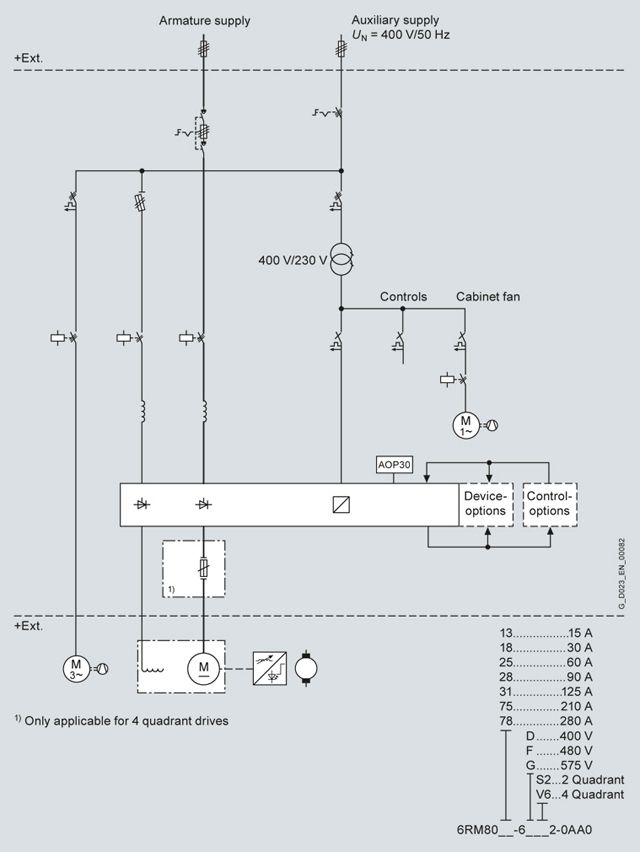
Single-line circuit diagram, rated DC current ≤ 280 A
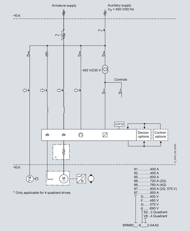
Single-line circuit diagram, rated DC current ≤ 850 A
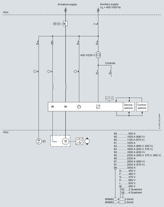
Single-line circuit diagram, rated DC current ≤ 3 000 A
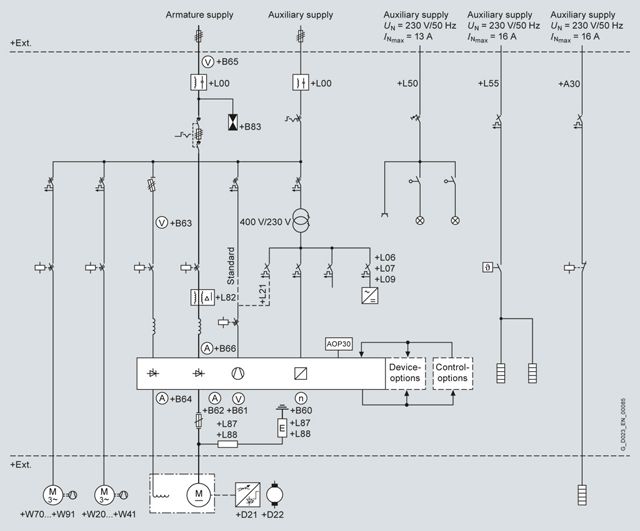
Single-line circuit diagram showing the options that are relevant from an electrical perspective
Assignment of terminals and connectors
Overview
Overview of the terminals and connector assignment of SINAMICS DC MASTER Cabinet. When using special options, additional terminals are available. A description is then provided in the particular option description.
Terminal strip
Function
Remark
Max. connectable conductor cross-section
Terminals
-X0 armature circuit supply
-X0
1 ... 3, PE
Supply, 3 AC armature circuit
Only from 15 up to 600 A, and only for option L00 (radio interference suppression filter), otherwise connected directly at the main switch or circuit breaker, -X0 is then no longer applicable.
Dependent on the rated current, refer to the technical data.
-X1 auxiliary power supply 400 V 3 AC /50 Hz or 460 V 3 AC /60 Hz
-X1
1 ... 3, PE
Supply, 3 AC auxiliary power supply
In the basic version, an auxiliary power supply of 400 V 3 AC /50 Hz or 460 V 3 AC/60 Hz is required. For different voltages, option Y04 (auxiliary voltage 3 AC not the same as the standard voltage) is required.
If a 3 AC auxiliary voltage is not available, then option Y03 (auxiliary voltage 3 AC not available) can be specified,
connection -X1 is then omitted.
Note:
For rated DC currents 15 up to 850 A, terminal X1 is only provided in conjunction with option L00.Dependent on the option scope.
-X2 control terminals 24 V DC/230 V AC
-X2
1, 2
Group fault signal, tripped circuit breaker
Isolated contacts for 24 V DC up to max. 230 V AC.
2.5 mm2
3, 4
External Emergency Stop pushbutton
Not for option L57 or L59, circuit with 230 V AC,
An isolated, external contact (NC contact) is expected, which initiates the external Emergency Stop.2.5 mm2
5, 6
Control interlocking of main contactor
Only for option B30 (interlocking possibility for the supply circuit breaker), circuit with 230 V AC,
an external isolated contact to open the main contactor (up to 850 A) or infeed circuit breaker (from 950 A and higher) is expected. The wire jumpers inserted between these terminals in the factory must be removed.2.5 mm2
21, 22
External EMERGENCY OFF/ EMERGENCY STOP reset
Only for option L57 or L59, 24 V DC circuit.
2.5 mm2
23 ... 26
External EMERGENCY OFF/ EMERGENCY STOP pushbutton
Only for option L57 or L59, the external EMERGENCY OFF pushbutton should be connected with channel 1 (NC contact) at terminals 23, 24, and with channel 2 (NC contact) at terminals 25, 26. The wire jumpers inserted between these terminals in the factory must be removed.
24 V DC circuit.2.5 mm2
31 ... 40
Ground fault signal, fault and alarm
Only for option L87 or L88 (ground fault monitoring in an ungrounded line supply), two isolated changeover contacts of the ground fault monitor for 24 V DC up to max. 230 V AC. These contacts can be parameterized to the required signals. A test can be initiated using an external pushbutton connected at terminals 37 and 38. A reset can be initiated using an external pushbutton (NC contact) connected at terminals 39, 40.
2.5 mm2
31 ... 40
Fault current relay trip
Only for option L82 (fault current monitoring in an ungrounded line supply), an isolated changeover contact of the fault current relay for 24 V DC up to max. 230 V AC at terminals 31 to 33 signals the trip; an external pushbutton can be connected to terminals 37 and 38 to initiate a test trip. A reset can be initiated using an external pushbutton (NC contact) connected at terminals 39, 40.
2.5 mm2
41 ... 43
Ruptured fuse/disconnector position 7VV3002
Only for option B83 (overvoltage protection), isolated signaling contact, which signals a ruptured fuse or the disconnector position in the overvoltage protection, for 24 V DC up to max. 230 V AC.
2.5 mm2
51, 52, PE
24 V DC supply voltage
Only for option L07 (24 V DC external power supply).
4 mm2
61 ... 64, PE
Motor holding brake
Only for option Y51 (motor holding brake), supply and feeder for a motor holding brake,
230 V 1 AC.2.5 mm2
-X3 motor interface (field, fan)
-X3
1, 2, PE
Motor connection, field circuit
Connectable cross-section depends on the selected cabinet type of at least 2.5 mm2 up to 10 mm2 at 40 A – and for option L85 (field current 85 A) up to 35 mm2 can be connected.
Dependent on the cabinet type, refer to the technical data.
3 ... 5, PE
Feeder, motor fan 1
4 mm2
6 ... 8, PE
Feeder, motor fan 2
Only for options W70 to W91.
4 mm2
-X4 auxiliary power supply 1 AC 230 V (optional)
-X4
1, 2, PE
Supply, cabinet lighting
Only for option L50 (cabinet lighting and service outlet),
230 V 1 AC, max. fuse 16 A, connectable cross-section, max. 2.5 mm2.2.5 mm2
3, 4, PE
Supply, cabinet heating
Only for option L55 (cabinet anti-condensation heating),
230 V 1 AC, max. fuse 16 A.2.5 mm2
5, 6, PE
Supply, motor heating
Only for option A30 (anti-condensation heating for the motor up to max. 2 000 W, 230 V),
230 V 1 AC, max. fusing 16 A.2.5 mm2
Terminals 1-3-5 and 2-4-6 can be connected on the customer side by inserting a wire jumper, so that these three options can also be supplied together.
6, 7, PE
Feeder, motor heating
Only for option A30 (anti-condensation heating for the motor up to max. 2 000 W, 230 V),
230 V 1 AC.2.5 mm2
-X71 TMC for CUD left (standard)
-X71
1 ... 64
Input/output signals of the left-hand CUD
On the terminal strip, all signals are available that exist at the CU, binary inputs/outputs, analog inputs/outputs, input for an incremental encoder, temperature measuring input, peer-to-peer interface.
1.5 mm2
-X72 TMC for CUD right (optional)
-X72
1 ... 64
Input/output signals of the right-hand CUD
Only for option G10 or G11 (additional CU right)
On the terminal strip, all signals are available that exist at the CU, binary inputs/outputs, analog inputs/outputs, input for an incremental encoder, temperature measuring input, peer-to-peer interface.1.5 mm2
SINAMICS DC MASTER Converter interfaces
X100, X101
DRIVE-CLiQ
Only with the Advanced CUD (option G00, G11)
X126
PROFIBUS
The standard CUD and/or Advanced CUD, or for commissioning, integrated in the cabinet door (option L91).
X165, X166
Parallel interface
The standard CUD and/or Advanced CUD.
X178
RS485 interface
Assigned as standard, as this is used to connect the AOP30.
(X179)
(RS232 interface)
For use as USS interface; cannot be used in parallel to interface X178.
XT1
Analog tachometer
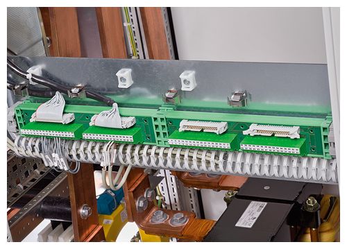
The Terminal Module Cabinet (TMC -X71, -X72)
The Terminal Module Cabinet (TMC) allows cables associated with CUD standard signals to be connected in the lower section of the SINAMICS DC MASTER Cabinet that is easy to access (e.g. digital and analog inputs/outputs, peer-to-peer interface, incremental encoder, temperature sensor). This is possible, as the appropriate interfaces (X177 of the CUD) are routed to the TMC using an adapter board (X71, X72).
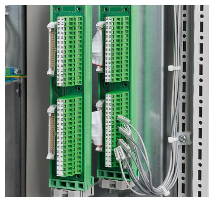
TMC terminals
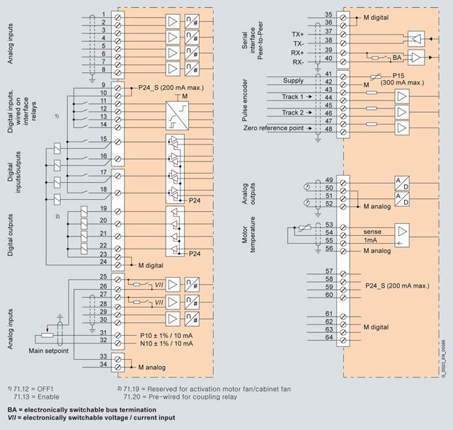
Connection diagram of the TMC with typical connections (max. 1.5 mm2)
Terminals at the Terminal Module Cabinet X71/X72
Assignment of terminals X71 (left-hand CUD) and X72 (right-hand CUD)
Terminal
X71/X72Function
Technical data
Analog inputs (user-assignable inputs)
1
2AI3 +
AI3 –Analog input 3
Input type (signal type):
Differential input ± 10 V; 150 kΩ
Resolution approx. 5.4 mV (± 11 bits)
Common-mode controllability: ± 15 V3
4AI4 +
AI4 –Analog input 4
5
6AI5 +
AI5 –Analog input 5
7
8AI6 +
AI6 –Analog input 6
Digital inputs (user-assignable inputs)
9
1024 V DC
24 V supply (output)
24 V DC, short-circuit proof
Max. load 200 mA (terminals 9 and 10 together),
internal supply referred to internal ground11
DI0
Digital input 0
H signal: +15 … +30 V
L signal: –30 … +5 V or terminal open-circuit
8.5 mA at 24 V12
DI1
Digital input 1
13
DI2
Digital input 2
14
DI3
Digital input 3
Digital inputs/outputs (user-assignable inputs/outputs)
15
DI/
DO4Digital input
/output 4Type, input/output parameterizable
Input features:
H signal: +15 … +30 V
L signal: 0 … +5 V or terminal open-circuit
8.5 mA at 24 VOutput features:
H signal: +20 … +26 V
L signal: 0 … +2 V
Short-circuit proof, 100 mA
Internal protective circuit (free wheeling diode)For overload: Alarm A60018
16
DI/
DO5Digital input
/output 517
DI/
DO6Digital input
/output 618
DI/
DO7Digital input
/output 719
DO0
Digital output 0
H signal: +20 … +26 V
L signal: 0 … +2 V
Short-circuit proof, 100 mA
Internal protective circuit (free wheeling diode)For overload: Alarm A60018
20
DO1
Digital output 1
21
DO2
Digital output 2
22
DO3
Digital output 3
23, 24
M
Ground, digital
Analog inputs, setpoint inputs (user-assignable inputs)
25
26AI0 +
AI0 –Analog input 0
Main setpointInput type (signal type), parameterizable:
- Differential input ± 10 V; 150 kΩ
- Current input 0 … 20 mA; 300 Ω or 4 … 20 mA; 300 Ω
Resolution approx. 0.66 mV (± 14 bits)
Common-mode controllability: ± 15 V27
28AI1 +
AI1 –Analog input 1
29
30AI2 +
AI2 –Analog input 2
Input type (signal type):
- Differential input ± 10 V; 150 kΩ
Resolution approx. 0.66 mV (± 14 bits)
Common-mode controllability: ± 15 VReference voltage
31
32P10
N10Reference voltage ± 10 V (output)
Tolerance ± 1 % at 25 °C
Stability 0.1 % per 10 K
10 mA short-circuit proof33, 34
M
Ground, analog
Serial interface, peer-to-peer RS485
35, 36
M
Ground, digital
37
TX+
Send line +
4-wire send cable, positive differential output
38
TX–
Send line –
4-wire send cable, negative differential output
39
RX+
Receive cable +
4-wire receive cable, positive differential output
40
RX–
Receive cable –
4-wire receive cable, negative differential output
Incremental encoder input
41
Incremental encoder supply
+13.7 … +15.2 V, 300 mA short-circuit proof (electronically protected)
For overload: Alarm A6001842
Ground, incremental encoder
43
Track 1 positive connection
Load: ≤ 5.25 mA at 15 V (without switching losses)
Pulse duty factor: 1:1Data regarding the cables, cable length, shield support, input pulse levels, hysteresis, track offset, pulse frequency, see below
44
Track 1 negative connection
45
Track 2 positive connection
46
Track 2 negative connection
47
Zero mark, positive connection
48
Zero mark, negative connection
Analog outputs (user-assignable outputs)
49
AO0
Analog output 0
± 10 V, max. 2 mA short-circuit proof, resolution ± 15 bits
50
M
Ground, analog
51
AO1
Analog output 1
52
M
Ground, analog
Connections for temperature sensor (motor interface 1)
53
Temp 1
Sensor acc. to p50490
The cable to the temperature sensor on the motor must be shielded and connected to ground at both ends.
The cables for the Temp 1 and Temp 3 connections to the temperature sensor must be approximately the same length.
The sense cable (Temp 2) is used for compensating the cable resistances. If you are not using a sense cable, terminals 54 and 55 must be connected.54
Temp 2 (sense cable)
55
Temp 3
Terminals for ground and the 24 V DC supply
56
M
Ground, analog
57, 58, 59, 60
24 V DC
24 V supply (output)
24 V DC, short-circuit proof, max. load 200 mA (terminals 9, 10, 57, 58, 59 and 60 together), internal supply referred to ground, digital and ground, analog
61, 62, 63, 64
M
Ground, digital
C98043-A7119 TMC (Terminal Module Cabinet)
Технические данные
General technical data
Coolant temperature and installation altitude
Current derating
The permissible coolant temperatures and installation altitudes for SINAMICS DC MASTER Cabinet as well as the associated maximum permissible load in continuous operation can be taken from the following table (the load is specified as a % of the rated DC current).
Note:
The rated DC current of the drive cabinets corresponds to the rated DC current of the DC converters installed in them. The degree of protection and cooling type of the drive cabinets as well as the coolant temperature and installation altitude influence the max. permissible load in continuous operation. In practice, the rated current of the DC motor lies significantly below the rated DC current of the next largest converter in order to be able to fully utilize the high overload capability of the motor. The derating factors below should be taken into account for the particular application.
Example:
Rated current of the DC motor 450 A, coolant temperature 40 °C, installation altitude of the drive cabinet 2 000 m, selected rated DC current of the converter 600 A, derating factor 81 %.Result:
The maximum permissible load of the drive cabinet in continuous operation is 486 A, and is therefore sufficient for the motor.Maximum permissible load of the drive cabinets in continuous operation
(load specified as a % of the rated DC current)Installation altitude above sea level
(The derating factors for intermediate values can be obtained through interpolation.)Ambient or coolant temperature
Units
1 000 m
2 000 m
3 000 m
4 000 m
5 000 m
from 1500 A ⇒
⇓⇒
⇓⇒
⇓⇒
⇓⇒
⇓from 950 A ⇒
⇓⇒
⇓⇒
⇓⇒
⇓⇒
⇓from 720 A ⇒
⇓⇒
⇓⇒
⇓⇒
⇓⇒
⇓from 210 A ⇒
⇓⇒
⇓⇒
⇓⇒
⇓⇒
⇓up to 125 A ⇒
⇓⇒
⇓⇒
⇓⇒
⇓⇒
⇓Degree of protection IP20 up to IP21
25 °C
100%
100%
100%
100%
100%
100%
96%
93%
97%
93%
96%
86%
83%
87%
83%
86%
76%
73%
77%
73%
78%
68%
65%
69%
65%
30 °C
100%
100%
100%
100%
100%
100%
91%
88%
92%
88%
90%
81%
78%
82%
78%
80%
71%
68%
72%
68%
35 °C
100%
100%
95%
99%
95%
94%
86%
83%
87%
83%
84%
76%
73%
77%
73%
40 °C
100%
95%
90%
94%
90%
88%
81%
78%
82%
78%
45 °C
94%
90%
85%
89%
85%
82%
76%
73%
77%
73%
50 °C
88%
Degree of protection IP23, IP43, IP54
25 °C
100%
100%
100%
100%
100%
100%
98%
96%
98%
98%
96%
88%
86%
88%
88%
86%
78%
76%
78%
78%
78%
70%
68%
70%
70%
30 °C
100%
100%
100%
100%
100%
100%
93%
91%
93%
93%
90%
83%
81%
83%
83%
80%
73%
71%
73%
73%
35 °C
100%
100%
98%
100%
100%
94%
88%
86%
88%
88%
84%
78%
76%
78%
78%
40 °C
100%
95%
93%
95%
95%
88%
83%
81%
83%
83%
45 °C
94%
90%
88%
90%
90%
82%
78%
76%
78%
78%
50 °C
88%
Voltage derating
The cabinets can be operated up to an installation altitude of 4 000 m above sea level with the specified rated supply voltages. The line supply voltages may have overvoltage category III with respect to ground. For installation altitudes above 4 000 m, in some cases, it will be necessary to reduce the supply voltage or ensure that overvoltage category II is maintained. Detailed information is provided in the Operating Instructions.
Installation location
In their basic version (IP20), SINAMICS DC MASTER Cabinet drive cabinets are intended for use in closed electrical rooms (according to EN 61800-5-1).
These rooms must be dry and dust free, in order to prevent deposits of dirt accumulating, which in conjunction with moisture, could result in a conductive connection between live parts.
In plants, frequently electrical operating rooms have central power and fresh air supplies, which fulfill these requirements. If this is not the case, then the drive cabinet must be ordered with a higher degree of protection by specifying the appropriate options (M21, M23, M43, M54 and M58).
Relevant standards
EN 50274
Low-voltage switchgear and controlgear assemblies: Protection against electric shock – protection against accidental, direct contact with dangerous live parts, option M60 provides additional touch protection in accordance with BGV A3
EN 60529
Degrees of protection provided by the enclosures (IP code)
EN 61800-3
Adjustable speed electrical power drive systems, Part 3 – EMC product standard including specific test methods
EN 61800‑5‑1
Adjustable speed electrical power drive systems – Part 5‑1: Requirements regarding safety – electrical, thermal, and energy requirements
EN 62477‑1 (product standard, combines safety-relevant standards such as IEC 61800‑5‑1, IEC 60204‑1)
Safety requirements for power semiconductor converter systems – Part 1: General information
EN 60204‑1 (VDE 0113‑1) where applicable
Safety of machinery – Electrical equipment of machines – Part 1: General requirements
The following standards are applicable for the SINAMICS DC MASTER DC Converter chassis units
EN 60146‑1‑1; EN 61800‑5‑1; IEC 62103 (identical with EN 50178). Additional information is provided in Catalog D 23.1.
Electrical data
Overvoltage category
Category ll according to EN 61800‑5‑1 within line supply circuits
Category lll according to EN 61800‑5‑1 for line supply circuits with respect to the surroundings (other line supply circuits, enclosure, electronics)Overvoltage strength
Class 1 acc. to EN 50178
Radio interference suppression
SINAMICS DC MASTER Cabinet are operated in industrial environments and fulfill the requirements of EN 61800‑3, Categories C3 and C4. Radio interference suppression filters are required for use in Category C2 (option L00)
Auxiliary power supply
400 V 3 AC at 50 Hz, optional: 60 Hz and/or other voltages
Overload capability
x × In 1.8
Mechanical data
Degree of protection
IP20 according to EN 60529; optional: IP21, IP23, IP43 and IP54
Protection class
Class 1 acc. to EN 61140
Cooling type
Increased air cooling with integrated fan 0 up to 55 °C; the derating depends on the ambient temperature and installation altitude; see the table on the current derating
Closed-loop control constancy
- for pulse encoder operation and digital setpoint
Δn = 0.006 % of the rated motor speed
- for analog tachometer and analog setpoint 1)
Δn = 0.1 % of the rated motor speed
Environmental compatibility
Materials free of hazardous substances have been used for all of the essential parts. Only very few materials containing halogens are used for cable insulation and cable ducts (alternative designs available on request). All of the materials correspond to the RoHS criteria, with the exception of the backup battery in the AOP30. Environmental compatibility is also a key criterion in selecting supplier parts.
Environmental conditions
Permissible ambient temperature during storage and transport
–25 ... +70 °C
Permissible humidity
Relative air humidity ≤ 95 % (75 % at 17 °C as annual average, 95 % at 24 °C max., condensation is not permissible)
Climate class
3K3 according to EN 60721‑3‑3
Insulation
Pollution degree 2 according to EN 61800‑5‑1
Condensation not permissibleInstallation altitude
≤ 1 000 m above sea level (100 % load capability)
> 1 000 ... 5 000 m above sea level (see under "Coolant temperature and installation altitude")Mechanical stability
Storage
Transport
Operation
Vibratory load
1M2 according to EN 60721‑3‑1
(toppling not permissible)1.5 mm at 2 ... 9 Hz, 5 m/s2 at 9 ... 200 Hz
acc. to EN 60721‑3‑2
(toppling not permissible)3M2 according to EN 60721-3-3
Shock load
1M2 according to EN 60721‑3‑1
(toppling not permissible)40 m/s2 at 11 ms acc. to
acc. to EN 60721‑3‑2
(toppling not permissible)3M2 according to EN 60721-3-3
Approvals
Version according to UL
A converter cabinet design according to UL can be ordered by specifying option U09. Certification must be separately carried out.
Marine version
With option M66, the cabinet is provided in a marine design for onboard applications. Certification by the appropriate authorities must be carried out separately.
1) Conditions:
The closed-loop control (PI control) constancy is referred to the rated motor speed and applies when the SINAMICS DC MASTER is in the warm operating condition. This is based on the following preconditions:- Temperature changes of ± 10 °C
- Line supply voltage changes of +10 %/–5 % of the rated input voltage
- Temperature coefficient of tachometer generator with temperature compensation: 0.15 every 10 °C (for analog tachometer generator only)
- Constant setpoint
Notes on dimensioning the fault current and insulation monitoring:
The basic version does not include any fault current monitoring devices. However, these can be ordered as option (L82 for grounded line supplies). Insulation monitoring according to the applicable regulations must be provided for operation in non-grounded IT line supplies. Options L87 or L88 are available to realize this.
Notes on touch protection:
In the standard version of the SINAMICS DC MASTER Cabinet, in compliance with the current standards, finger and back of hand protection is ensured when the cabinet doors are open. With option M60 "Additional touch protection", the drive cabinets are equipped with additional touch protection corresponding to BGV A3.
Notes on the armature circuit busbars:
Aluminum armature busbars are used for cabinets with rated DC currents of 1 500, 1 600, 1 900, 2 000 and 2 200 A. When selecting option M11, nickel-plated copper busbars are supplied.
SINAMICS DC MASTER Cabinet for 400 V 3 AC, 60 to 210 A, two-quadrant operation
Type
6RM8025-
6DS22‑0AA06RM8028-
6DS22‑0AA06RM8031-
6DS22‑0AA06RM8075-
6DS22‑0AA0Rated armature supply voltage
V
3 AC 400 (+15 %/–20 %)
Rated armature input current
A
49.8
74.7
103.75
174.3
Cooling air requirement
m³/h
800
800
800
800
Sound pressure level
dB (A)
72
72
72
72
Rated frequency
Hz
45 ... 65
45 ... 65
45 ... 65
45 ... 65
Rated DC voltage
V
485
485
485
485
Rated DC current
A
60
90
125
210
Overload capability
x × In
1.8
1.8
1.8
1.8
Rated power
kW
29.1
43.65
60.625
101.85
Power loss at rated DC current
W
463
592
691
1 152
Rated DC field voltage
V
max. 325
max. 325
max. 325
max. 325
Rated DC field current
A
10
10
10
15
Max. connection cross-sections 1)
- Line connection (3 phases and PE)
Number × mm2
1 × 16
1 × 25
1 × 50
1 × 95
- Armature circuit connection
Number × mm2
1 × 16
1 × 25
1 × 50
1 × 95
- Field circuit connection
Number × mm2
1 × 1.5
1 × 1.5
1 × 1.5
1 × 2.5
- Auxiliary power supply
mm2
2.5
2.5
2.5
4
Max. permissible fusing on the customer's side
(NH fuse gL/gG)- Power connections
A
63
80
125
200
- Max. permissible short-circuit current
kA
50 2)
50 2)
50 2)
50 3)
- Auxiliary power supply
A
16
16
16
25
- Max. permissible short-circuit current
kA
30
30
30
30
Normal ambient temperature in operation
°C
See the table on installation altitude and ambient temperature
Dimensions
- Width
mm
600
600
600
600
- Height
mm
2 326
2 326
2 326
2 326
- Depth
mm
600
600
600
600
Size
BC
BC
BC
BC
Weight, approx.
kg
233
233
240
263
1) With cable lugs according to DIN 46234 or DIN 46235; for units from 2 600 to 3 000 A, motor cables are only directly connected at the DC converter using cable lugs according to DIN 46234.
2) With option L00 (radio interference suppression filter), the maximum permissible short-circuit current is reduced to 43 kA.
3) With option L00 (radio interference suppression filter), the maximum permissible short-circuit current is reduced to 25 kA.
SINAMICS DC MASTER Cabinet for 400 V 3 AC, 280 to 850 A, two-quadrant operation
Type
6RM8078-
6DS22‑0AA06RM8081-
6DS22‑0AA06RM8085-
6DS22‑0AA06RM8087-
6DS22‑0AA0Rated armature supply voltage
V
3 AC 400 (+15 %/–20 %)
Rated armature input current
A
232.4
332
498
705.5
Cooling air requirement
m³/h
800
600
600
600
Sound pressure level
dB (A)
72
74
74
74
Rated frequency
Hz
45 ... 65
45 ... 65
45 ... 65
45 ... 65
Rated DC voltage
V
485
485
485
485
Rated DC current
A
280
400
600
850
Overload capability
x × In
1.8
1.8
1.8
1.8
Rated power
kW
135.8
194
291
412.25
Power loss at rated DC current
W
1 482
2 131
2 884
3 759
Rated DC field voltage
V
max. 325
max. 325
max. 325
max. 325
Rated DC field current
A
15
25
25
30
Max. connection cross-sections 1)
- Line connection (3 phases and PE)
Number × mm2
1 × 120
1 × 185
2 × 150
2 × 240
- Armature circuit connection
Number × mm2
2 × 50
1 × 185
2 × 150
4 × 95
- Field circuit connection
Number × mm2
1 × 2.5
1 × 4
1 × 4
1 × 4
- Auxiliary power supply
mm2
4
10
10
16
Max. permissible fusing on the customer's side
(NH fuse gL/gG)- Power connections
A
250
355
500
710
- Max. permissible short-circuit current
kA
50 2)
50
50
50
- Auxiliary power supply
A
25
50
50
63
- Max. permissible short-circuit current
kA
30
30
30
30
Normal ambient temperature in operation
°C
See the table on installation altitude and ambient temperature
Dimensions
- Width
mm
600
800
800
1 200
- Height
mm
2 326
2 200
2 200
2 200
- Depth
mm
600
600
600
600
Size
BC
CC
CC
DC
Weight, approx.
kg
273
320
340
490
1) With cable lugs according to DIN 46234 or DIN 46235; for units from 2 600 to 3 000 A, motor cables are only directly connected at the DC converter using cable lugs according to DIN 46234.
2) With option L00 (radio interference suppression filter), the maximum permissible short-circuit current is reduced to 25 kA.
SINAMICS DC MASTER Cabinet for 400 V 3 AC, 1 200 to 3 000 A, two-quadrant operation
Type
6RM8091-
6DS22‑0AA06RM8093-
4DS22‑0AA06RM8095-
4DS22‑0AA06RM8098-
4DS22‑0AA0Rated armature supply voltage
V
3 AC 400 (+15 %/–20 %)
Rated armature input current
A
996
1 328
1 660
2 490
Cooling air requirement
m³/h
1 000
3 000
3 000
3 000
Sound pressure level
dB (A)
76
78
78
78
Rated frequency
Hz
45 ... 65
45 ... 65
45 ... 65
45 ... 65
Rated DC voltage
V
485
485
485
485
Rated DC current
A
1 200
1 600
2 000
3 000
Overload capability
x × In
1.8
1.8
1.8
1.8
Rated power
kW
582
776
970
1 455
Power loss at rated DC current
W
4 697
6 430
7 618
11 747
Rated DC field voltage
V
max. 390
max. 390
max. 390
max. 390
Rated DC field current
A
30
40
40
40
Max. connection cross-sections 1)
- Line connection (3 phases and PE)
Number × mm2
4 × 150
6 × 150
6 × 185
8 × 240
- Armature circuit connection
Number × mm2
4 × 185
8 × 95
8 × 150
8 × 240
- Field circuit connection
Number × mm2
1 × 4
1 × 6
1 × 6
1 × 6
- Auxiliary power supply
mm2
16
35
35
35
Max. permissible fusing on the customer's side
(NH fuse gL/gG)- Power connections
A
– 2)
– 2)
– 2)
– 2)
- Max. permissible short-circuit current
kA
65
75
75
75
- Auxiliary power supply
A
63
100
100
100
- Max. permissible short-circuit current
kA
30
50
50
50
Normal ambient temperature in operation
°C
See the table on installation altitude and ambient temperature
Dimensions
- Width
mm
1 200
1 400
1 400
1 400
- Height
mm
2 200
2 200
2 200
2 200
- Depth
mm
600
600
600
600
Size
DC
EC
EC
EC
Weight, approx.
kg
570
760
800
930
1) With cable lugs according to DIN 46234 or DIN 46235; for units from 2 600 to 3 000 A, motor cables are only directly connected at the DC converter using cable lugs according to DIN 46234.
2) It must be ensured that the maximum permissible short-circuit current at the supply switch of the drive cabinet is not exceeded.
SINAMICS DC MASTER Cabinet for 480 V 3 AC, 60 to 280 A, two-quadrant operation
Type
6RM8025-
6FS22‑0AA06RM8028-
6FS22‑0AA06RM8031-
6FS22‑0AA06RM8075-
6FS22‑0AA06RM8078-
6FS22‑0AA0Rated armature supply voltage
V
3 AC 480 (+10 %/–20 %)
Rated armature input current
A
49.8
74.7
103.75
174.3
232.4
Cooling air requirement
m³/h
800
800
800
800
800
Sound pressure level
dB (A)
72
72
72
72
72
Rated frequency
Hz
45 ... 65
45 ... 65
45 ... 65
45 ... 65
45 ... 65
Rated DC voltage
V
575
575
575
575
575
Rated DC current
A
60
90
125
210
280
Overload capability
x × In
1.8
1.8
1.8
1.8
1.8
Rated power
kW
34.5
51.75
71.875
120.75
161
Power loss at rated DC current
W
512
614
713
1 225
1 481
Rated DC field voltage
V
max. 390
max. 390
max. 390
max. 390
max. 390
Rated DC field current
A
10
10
10
15
15
Max. connection cross-sections 1)
- Line connection (3 phases and PE)
Number × mm2
1 × 16
1 × 25
1 × 50
1 × 95
1 × 120
- Armature circuit connection
Number × mm2
1 × 16
1 × 25
1 × 50
1 × 95
2 × 50
- Field circuit connection
Number × mm2
1 × 1.5
1 × 1.5
1 × 1.5
1 × 2.5
1 × 2.5
- Auxiliary power supply
mm2
2.5
2.5
2.5
4
4
Max. permissible fusing on the customer's side
(NH fuse gL/gG)- Power connections
A
63
80
125
200
250
- Max. permissible short-circuit current
kA
50 2)
50 2)
50 2)
50 3)
50 3)
- Auxiliary power supply
A
16
16
16
25
25
- Max. permissible short-circuit current
kA
30
30
30
30
30
Normal ambient temperature in operation
°C
See the table on installation altitude and ambient temperature
Dimensions
- Width
mm
600
600
600
600
600
- Height
mm
2 326
2 326
2 326
2 326
2 326
- Depth
mm
600
600
600
600
600
Size
BC
BC
BC
BC
BC
Weight, approx.
kg
233
238
240
273
273
1) With cable lugs according to DIN 46234 or DIN 46235; for units from 2 600 to 3 000 A, motor cables are only directly connected at the DC converter using cable lugs according to DIN 46234.
2) With option L00 (radio interference suppression filter), the maximum permissible short-circuit current is reduced to 43 kA.
3) With option L00 (radio interference suppression filter), the maximum permissible short-circuit current is reduced to 25 kA.
SINAMICS DC MASTER Cabinet for 480 V 3 AC, 450 to 1 200 A, two-quadrant operation
Type
6RM8082-
6FS22‑0AA06RM8085-
6FS22‑0AA06RM8087-
6FS22‑0AA06RM8091-
6FS22‑0AA0Rated armature supply voltage
V
3 AC 480 (+10 %/–20 %)
Rated armature input current
A
373.5
498
705.5
996
Cooling air requirement
m³/h
600
600
600
1 000
Sound pressure level
dB (A)
74
74
74
76
Rated frequency
Hz
45 ... 65
45 ... 65
45 ... 65
45 ... 65
Rated DC voltage
V
575
575
575
575
Rated DC current
A
450
600
850
1 200
Overload capability
x × In
1.8
1.8
1.8
1.8
Rated power
kW
258.75
345
488.75
690
Power loss at rated DC current
W
2 377
3 097
3 983
4 857
Rated DC field voltage
V
max. 390
max. 390
max. 390
max. 390
Rated DC field current
A
25
25
30
30
Max. connection cross-sections 1)
- Line connection (3 phases and PE)
Number × mm2
2 × 120
2 × 150
2 × 240
4 × 150
- Armature circuit connection
Number × mm2
2 × 95
2 × 150
4 × 95
4 × 185
- Field circuit connection
Number × mm2
1 × 4
1 × 4
1 × 4
1 × 4
- Auxiliary power supply
mm2
10
10
16
16
Max. permissible fusing on the customer's side
(NH fuse gL/gG)- Power connections
A
400
500
710
– 2)
- Max. permissible short-circuit current
kA
50
50
50
65
- Auxiliary power supply
A
50
50
63
63
- Max. permissible short-circuit current
kA
30
30
30
30
Normal ambient temperature in operation
°C
See the table on installation altitude and ambient temperature
Dimensions
- Width
mm
800
800
1 200
1 200
- Height
mm
2 200
2 200
2 200
2 200
- Depth
mm
600
600
600
600
Size
CC
CC
DC
DC
Weight, approx.
kg
340
355
500
570
1) With cable lugs according to DIN 46234 or DIN 46235; for units from 2 600 to 3 000 A, motor cables are only directly connected at the DC converter using cable lugs according to DIN 46234.
2) It must be ensured that the maximum permissible short-circuit current at the supply switch of the drive cabinet is not exceeded.
SINAMICS DC MASTER Cabinet for 575 V 3 AC, 60 to 400 A, two-quadrant operation
Type
6RM8025-
6GS22‑0AA06RM8031-
6GS22‑0AA06RM8075-
6GS22‑0AA06RM8081-
6GS22‑0AA0Rated armature supply voltage
V
3 AC 575 (+10 %/–20 %)
Rated armature input current
A
49.8
103.75
174.3
332
Cooling air requirement
m³/h
800
800
800
600
Sound pressure level
dB (A)
72
72
72
74
Rated frequency
Hz
45 ... 65
45 ... 65
45 ... 65
45 ... 65
Rated DC voltage
V
690
690
690
690
Rated DC current
A
60
125
210
400
Overload capability
x × In
1.8
1.8
1.8
1.8
Rated power
kW
41.4
86.25
144.9
276
Power loss at rated DC current
W
487
762
1 284
2 439
Rated DC field voltage
V
max. 390
max. 390
max. 390
max. 390
Rated DC field current
A
10
10
15
25
Max. connection cross-sections 1)
- Line connection (3 phases and PE)
Number × mm2
1 × 16
1 × 50
1 × 95
1 × 185
- Armature circuit connection
Number × mm2
1 × 16
1 × 50
1 × 95
1 × 185
- Field circuit connection
Number × mm2
1 × 1.5
1 × 1.5
1 × 2.5
1 × 4
- Auxiliary power supply
mm2
2.5
2.5
4
10
Max. permissible fusing on the customer's side
(NH fuse gL/gG)- Power connections
A
63
125
200
355
- Max. permissible short-circuit current
kA
50 2)
50 2)
50 3)
50
- Auxiliary power supply
A
16
16
25
50
- Max. permissible short-circuit current
kA
30
30
30
30
Normal ambient temperature in operation
°C
See the table on installation altitude and ambient temperature
Dimensions
- Width
mm
600
600
600
800
- Height
mm
2 326
2 326
2 326
2 200
- Depth
mm
600
600
600
600
Size
BC
BC
BC
CC
Weight, approx.
kg
233
240
273
335
1) With cable lugs according to DIN 46234 or DIN 46235; for units from 2 600 to 3 000 A, motor cables are only directly connected at the DC converter using cable lugs according to DIN 46234.
2) With option L00 (radio interference suppression filter), the maximum permissible short-circuit current is reduced to 43 kA.
3) With option L00 (radio interference suppression filter), the maximum permissible short-circuit current is reduced to 25 kA.
SINAMICS DC MASTER Cabinet for 575 V 3 AC, 600 to 1 600 A, two-quadrant operation
Type
6RM8085-
6GS22‑0AA06RM8087-
6GS22‑0AA06RM8090-
6GS22‑0AA06RM8093-
4GS22‑0AA0Rated armature supply voltage
V
3 AC 575 (+10 %/–20 %)
Rated armature input current
A
498
664
913
1 328
Cooling air requirement
m³/h
600
600
1 000
3 000
Sound pressure level
dB (A)
74
74
76
78
Rated frequency
Hz
45 ... 65
45 ... 65
45 ... 65
45 ... 65
Rated DC voltage
V
690
690
690
690
Rated DC current
A
600
800
1 100
1 600
Overload capability
x × In
1.8
1.8
1.8
1.8
Rated power
kW
414
552
759
1 104
Power loss at rated DC current
W
3 190
3 932
4 583
6 988
Rated DC field voltage
V
max. 390
max. 390
max. 390
max. 390
Rated DC field current
A
25
30
30
40
Max. connection cross-sections 1)
- Line connection (3 phases and PE)
Number × mm2
2 × 150
2 × 240
4 × 150
6 × 150
- Armature circuit connection
Number × mm2
2 × 150
4 × 95
4 × 120
8 × 95
- Field circuit connection
Number × mm2
1 × 4
1 × 4
1 × 4
1 × 6
- Auxiliary power supply
mm2
10
16
16
35
Max. permissible fusing on the customer's side
(NH fuse gL/gG)- Power connections
A
500
710
– 2)
– 2)
- Max. permissible short-circuit current
kA
50
50
65
75
- Auxiliary power supply
A
50
63
63
100
- Max. permissible short-circuit current
kA
30
30
30
50
Normal ambient temperature in operation
°C
See the table on installation altitude and ambient temperature
Dimensions
- Width
mm
800
1 200
1 200
1 400
- Height
mm
2 200
2 200
2 200
2 200
- Depth
mm
600
600
600
600
Size
CC
DC
DC
EC
Weight, approx.
kg
355
515
600
775
1) With cable lugs according to DIN 46234 or DIN 46235; for units from 2 600 to 3 000 A, motor cables are only directly connected at the DC converter using cable lugs according to DIN 46234.
2) It must be ensured that the maximum permissible short-circuit current at the supply switch of the drive cabinet is not exceeded.
SINAMICS DC MASTER Cabinet for 575 V 3 AC, 2 000 to 2 800 A, two-quadrant operation
Type
6RM8095-
4GS22‑0AA06RM8096-
4GS22‑0AA06RM8097-
4GS22‑0AA0Rated armature supply voltage
V
3 AC 575 (+10 %/–20 %)
Rated armature input current
A
1 660
1 826
2 324
Cooling air requirement
m³/h
3 000
3 000
3 000
Sound pressure level
dB (A)
78
78
78
Rated frequency
Hz
45 ... 65
45 ... 65
45 ... 65
Rated DC voltage
V
690
690
690
Rated DC current
A
2 000
2 200
2 800
Overload capability
x × In
1.8
1.8
1.8
Rated power
kW
1 380
1 518
1 932
Power loss at rated DC current
W
8 090
8 408
11 937
Rated DC field voltage
V
max. 390
max. 390
max. 390
Rated DC field current
A
40
40
40
Max. connection cross-sections 1)
- Line connection (3 phases and PE)
Number × mm2
6 × 185
8 × 150
8 × 240
- Armature circuit connection
Number × mm2
8 × 150
8 × 185
8 × 240
- Field circuit connection
Number × mm2
1 × 6
1 × 6
1 × 6
- Auxiliary power supply
mm2
35
35
35
Max. permissible fusing on the customer's side
(NH fuse gL/gG)- Power connections
A
– 2)
– 2)
– 2)
- Max. permissible short-circuit current
kA
75
75
75
- Auxiliary power supply
A
100
100
100
- Max. permissible short-circuit current
kA
50
50
50
Normal ambient temperature in operation
°C
See the table on installation altitude and ambient temperature
Dimensions
- Width
mm
1 400
1 400
1 400
- Height
mm
2 200
2 200
2 200
- Depth
mm
600
600
600
Size
EC
EC
EC
Weight, approx.
kg
830
930
1 010
1) With cable lugs according to DIN 46234 or DIN 46235; for units from 2 600 to 3 000 A, motor cables are only directly connected at the DC converter using cable lugs according to DIN 46234.
2) It must be ensured that the maximum permissible short-circuit current at the supply switch of the drive cabinet is not exceeded.
SINAMICS DC MASTER Cabinet for 690 V 3 AC, 720 to 2 600 A, two-quadrant operation
Type
6RM8086-
6KS22‑0AA06RM8090-
6KS22‑0AA06RM8093-
4KS22‑0AA06RM8095-
4KS22‑0AA06RM8097-
4KS22‑0AA0Rated armature supply voltage
V
3 AC 690 (+10 %/–20 %)
Rated armature input current
A
597.6
830
1 245
1 660
2 158
Cooling air requirement
m³/h
600
1 000
3 000
3 000
3 000
Sound pressure level
dB (A)
74
76
78
78
78
Rated frequency
Hz
45 ... 65
45 ... 65
45 ... 65
45 ... 65
45 ... 65
Rated DC voltage
V
830
830
830
830
830
Rated DC current
A
720
1 000
1 500
2 000
2 600
Overload capability
x × In
1.8
1.8
1.8
1.8
1.8
Rated power
kW
597.6
830
1 245
1 660
2 158
Power loss at rated DC current
W
4 012
4 642
7 627
9 175
12 007
Rated DC field voltage
V
max. 390
max. 390
max. 390
max. 390
max. 390
Rated DC field current
A
30
30
40
40
40
Max. connection cross-sections 1)
- Line connection (3 phases and PE)
Number × mm2
2 × 240
4 × 120
6 × 120
6 × 185
8 × 240
- Armature circuit connection
Number × mm2
4 × 95
4 × 120
8 × 95
8 × 150
8 × 240
- Field circuit connection
Number × mm2
1 × 4
1 × 4
1 × 6
1 × 6
1 × 6
- Auxiliary power supply
mm2
16
16
35
35
35
Max. permissible fusing on the customer's side
(NH fuse gL/gG)- Power connections
A
630
– 2)
– 2)
– 2)
– 2)
- Max. permissible short-circuit current
kA
50
65
75
75
75
- Auxiliary power supply
A
63
63
100
100
100
- Max. permissible short-circuit current
kA
30
30
50
50
50
Normal ambient temperature in operation
°C
See the table on installation altitude and ambient temperature
Dimensions
- Width
mm
1 200
1 200
1 400
1 400
1 600
- Height
mm
2 200
2 200
2 200
2 200
2 200
- Depth
mm
600
600
600
600
600
Size
DC
DC
EC
EC
FC
Weight, approx.
kg
515
600
795
830
1 050
1) With cable lugs according to DIN 46234 or DIN 46235; for units from 2 600 to 3 000 A, motor cables are only directly connected at the DC converter using cable lugs according to DIN 46234.
2) It must be ensured that the maximum permissible short-circuit current at the supply switch of the drive cabinet is not exceeded.
SINAMICS DC MASTER Cabinet for 830 V 3 AC, 950 to 1 900 A and 950 V 3 AC, 2 200 A, two-quadrant operation
Type
6RM8088-
6LS22‑0AA06RM8093-
4LS22‑0AA06RM8095-
4LS22‑0AA06RM8096-
4MS22‑0AA0Rated armature supply voltage
V
3 AC 830 (+10 %/–20 %)
3 AC 950 (+15 %/–20 %)
Rated armature input current
A
788.5
1 245
1 577
1 826
Cooling air requirement
m³/h
1 000
3 000
3 000
3 000
Sound pressure level
dB (A)
76
78
78
78
Rated frequency
Hz
45 ... 65
45 ... 65
45 ... 65
45 ... 65
Rated DC voltage
V
1 000
1 000
1 000
1 140
Rated DC current
A
950
1 500
1 900
2 200
Overload capability
x × In
1.8
1.8
1.8
1.8
Rated power
kW
950
1 500
1 900
2 508
Power loss at rated DC current
W
4 911
8 039
9 986
12 957
Rated DC field voltage
V
max. 390
max. 390
max. 390
max. 390
Rated DC field current
A
30
40
40
40
Max. connection cross-sections 1)
- Line connection (3 phases and PE)
Number × mm2
4 × 120
6 × 120
6 × 185
8 × 150
- Armature circuit connection
Number × mm2
4 × 120
8 × 95
8 × 150
8 × 185
- Field circuit connection
Number × mm2
1 × 4
1 × 6
1 × 6
1 × 6
- Auxiliary power supply
mm2
16
35
35
35
Max. permissible fusing on the customer's side
(NH fuse gL/gG)- Power connections
A
– 2)
– 2)
– 2)
– 2)
- Max. permissible short-circuit current
kA
50
50
50
50
- Auxiliary power supply
A
63
100
100
100
- Max. permissible short-circuit current
kA
30
50
50
50
Normal ambient temperature in operation
°C
See the table on installation altitude and ambient temperature
Dimensions
- Width
mm
1 200
1 400
1 400
1 600
- Height
mm
2 200
2 200
2 200
2 200
- Depth
mm
600
600
600
600
Size
DC
EC
EC
FC
Weight, approx.
kg
600
825
905
1 050
1) With cable lugs according to DIN 46234 or DIN 46235; for units from 2 600 to 3 000 A, motor cables are only directly connected at the DC converter using cable lugs according to DIN 46234.
2) It must be ensured that the maximum permissible short-circuit current at the supply switch of the drive cabinet is not exceeded.
SINAMICS DC MASTER Cabinet for 400 V 3 AC, 15 to 90 A, four-quadrant operation
Type
6RM8013-
6DV62‑0AA06RM8018-
6DV62‑0AA06RM8025-
6DV62‑0AA06RM8028-
6DV62‑0AA0Rated armature supply voltage
V
3 AC 400 (+15 %/–20 %)
Rated armature input current
A
12
25
50
75
Cooling air requirement
m³/h
800
800
800
800
Sound pressure level
dB (A)
72
72
72
72
Rated frequency
Hz
45 ... 65
45 ... 65
45 ... 65
45 ... 65
Rated DC voltage
V
420
420
420
420
Rated DC current
A
15
30
60
90
Overload capability
x × In
1.8
1.8
1.8
1.8
Rated power
kW
6.3
12.6
25.2
37.8
Power loss at rated DC current
W
292
372
485
587
Rated DC field voltage
V
max. 325
max. 325
max. 325
max. 325
Rated DC field current
A
3
5
10
10
Max. connection cross-sections 1)
- Line connection (3 phases and PE)
Number × mm2
1 × 2.5
1 × 6
1 × 16
1 × 25
- Armature circuit connection
Number × mm2
1 × 2.5
1 × 6
1 × 16
1 × 25
- Field circuit connection
Number × mm2
1 × 1.5
1 × 1.5
1 × 1.5
1 × 1.5
- Auxiliary power supply
mm2
2.5
2.5
2.5
2.5
Max. permissible fusing on the customer's side
(NH fuse gL/gG)- Power connections
A
20
32
63
80
- Max. permissible short-circuit current
kA
50 2)
50 2)
50 2)
50 2)
- Auxiliary power supply
A
16
16
16
16
- Max. permissible short-circuit current
kA
30
30
30
30
Normal ambient temperature in operation
°C
See the table on installation altitude and ambient temperature
Dimensions
- Width
mm
600
600
600
600
- Height
mm
2 326
2 326
2 326
2 326
- Depth
mm
600
600
600
600
Size
BC
BC
BC
BC
Weight, approx.
kg
233
213
233
233
1) With cable lugs according to DIN 46234 or DIN 46235; for units from 2 600 to 3 000 A, motor cables are only directly connected at the DC converter using cable lugs according to DIN 46234.
2) With option L00 (radio interference suppression filter), the maximum permissible short-circuit current is reduced to 43 kA.
SINAMICS DC MASTER Cabinet for 400 V 3 AC, 125 to 400 A, four-quadrant operation
Type
6RM8031-
6DV62‑0AA06RM8075-
6DV62‑0AA06RM8078-
6DV62‑0AA06RM8081-
6DV62‑0AA0Rated armature supply voltage
V
3 AC 400 (+15 %/–20 %)
Rated armature input current
A
104
174
232
332
Cooling air requirement
m³/h
800
800
800
600
Sound pressure level
dB (A)
72
72
72
74
Rated frequency
Hz
45 ... 65
45 ... 65
45 ... 65
45 ... 65
Rated DC voltage
V
420
420
420
420
Rated DC current
A
125
210
280
400
Overload capability
x × In
1.8
1.8
1.8
1.8
Rated power
kW
52.5
88.2
117.6
168
Power loss at rated DC current
W
726
1 202
1 557
2 226
Rated DC field voltage
V
max. 325
max. 325
max. 325
max. 325
Rated DC field current
A
10
15
15
25
Max. connection cross-sections 1)
- Line connection (3 phases and PE)
Number × mm2
1 × 50
1 × 95
1 × 120
1 × 185
- Armature circuit connection
Number × mm2
1 × 50
1 × 95
2 × 50
1 × 185
- Field circuit connection
Number × mm2
1 × 1.5
1 × 2.5
1 × 2.5
1 × 4
- Auxiliary power supply
mm2
2.5
4
4
10
Max. permissible fusing on the customer's side
(NH fuse gL/gG)- Power connections
A
125
200
250
355
- Max. permissible short-circuit current
kA
50 2)
50 3)
50 3)
50
- Auxiliary power supply
A
16
25
25
50
- Max. permissible short-circuit current
kA
30
30
30
30
Normal ambient temperature in operation
°C
See the table on installation altitude and ambient temperature
Dimensions
- Width
mm
600
600
600
800
- Height
mm
2 326
2 326
2 326
2 200
- Depth
mm
600
600
600
600
Size
BC
BC
BC
CC
Weight, approx.
kg
240
263
273
320
1) With cable lugs according to DIN 46234 or DIN 46235; for units from 2 600 to 3 000 A, motor cables are only directly connected at the DC converter using cable lugs according to DIN 46234.
2) With option L00 (radio interference suppression filter), the maximum permissible short-circuit current is reduced to 43 kA.
3) With option L00 (radio interference suppression filter), the maximum permissible short-circuit current is reduced to 25 kA.
SINAMICS DC MASTER Cabinet for 400 V 3 AC, 600 to 1 600 A, four-quadrant operation
Type
6RM8085-
6DV62‑0AA06RM8087-
6DV62‑0AA06RM8091-
6DV62‑0AA06RM8093-
4DV62‑0AA0Rated armature supply voltage
V
3 AC 400 (+15 %/–20 %)
Rated armature input current
A
498
706
996
1 328
Cooling air requirement
m³/h
600
600
1 000
3 000
Sound pressure level
dB (A)
74
74
76
78
Rated frequency
Hz
45 ... 65
45 ... 65
45 ... 65
45 ... 65
Rated DC voltage
V
420
420
420
420
Rated DC current
A
600
850
1 200
1 600
Overload capability
x × In
1.8
1.8
1.8
1.8
Rated power
kW
252
357
504
672
Power loss at rated DC current
W
2 984
3 939
4 697
6 430
Rated DC field voltage
V
max. 325
max. 325
max. 390
max. 390
Rated DC field current
A
25
30
30
40
Max. connection cross-sections 1)
- Line connection (3 phases and PE)
Number × mm2
2 × 150
2 × 240
4 × 150
6 × 150
- Armature circuit connection
Number × mm2
2 × 150
4 × 95
4 × 185
8 × 95
- Field circuit connection
Number × mm2
1 × 4
1 × 4
1 × 4
1 × 6
- Auxiliary power supply
mm2
10
16
16
35
Max. permissible fusing on the customer's side
(NH fuse gL/gG)- Power connections
A
500
710
– 2)
– 2)
- Max. permissible short-circuit current
kA
50
50
65
75
- Auxiliary power supply
A
50
63
63
100
- Max. permissible short-circuit current
kA
30
30
30
50
Normal ambient temperature in operation
°C
See the table on installation altitude and ambient temperature
Dimensions
- Width
mm
800
1 200
1 200
1 400
- Height
mm
2 200
2 200
2 200
2 200
- Depth
mm
600
600
600
600
Size
CC
DC
DC
EC
Weight, approx.
kg
340
490
570
780
1) With cable lugs according to DIN 46234 or DIN 46235; for units from 2 600 to 3 000 A, motor cables are only directly connected at the DC converter using cable lugs according to DIN 46234.
2) It must be ensured that the maximum permissible short-circuit current at the supply switch of the drive cabinet is not exceeded.
SINAMICS DC MASTER Cabinet for 400 V 3 AC, 2 000 to 3 000 A, four-quadrant operation
Type
6RM8095-
4DV62‑0AA06RM8098-
4DV62‑0AA0Rated armature supply voltage
V
3 AC 400 (+15 %/–20 %)
Rated armature input current
A
1 660
2 490
Cooling air requirement
m³/h
3 000
3 000
Sound pressure level
dB (A)
78
78
Rated frequency
Hz
45 ... 65
45 ... 65
Rated DC voltage
V
420
420
Rated DC current
A
2 000
3 000
Overload capability
x × In
1.8
1.8
Rated power
kW
840
1 260
Power loss at rated DC current
W
7 618
11 747
Rated DC field voltage
V
max. 390
max. 390
Rated DC field current
A
40
40
Max. connection cross-sections 1)
- Line connection (3 phases and PE)
Number × mm2
6 × 185
8 × 240
- Armature circuit connection
Number × mm2
8 × 150
8 × 240
- Field circuit connection
Number × mm2
1 × 6
1 × 6
- Auxiliary power supply
mm2
35
35
Max. permissible fusing on the customer's side
(NH fuse gL/gG)- Power connections
A
– 2)
– 2)
- Max. permissible short-circuit current
kA
75
75
- Auxiliary power supply
A
100
100
- Max. permissible short-circuit current
kA
50
50
Normal ambient temperature in operation
°C
See the table on installation altitude and ambient temperature
Dimensions
- Width
mm
1 400
1 400
- Height
mm
2 200
2 200
- Depth
mm
600
600
Size
EC
EC
Weight, approx.
kg
820
950
1) With cable lugs according to DIN 46234 or DIN 46235; for units from 2 600 to 3 000 A, motor cables are only directly connected at the DC converter using cable lugs according to DIN 46234.
2) It must be ensured that the maximum permissible short-circuit current at the supply switch of the drive cabinet is not exceeded.
SINAMICS DC MASTER Cabinet for 480 V 3 AC, 15 to 90 A, four-quadrant operation
Type
6RM8013-
6FV62‑0AA06RM8018-
6FV62‑0AA06RM8025-
6FV62‑0AA06RM8028-
6FV62‑0AA0Rated armature supply voltage
V
3 AC 480 (+10 %/–20 %)
Rated armature input current
A
12
25
50
75
Cooling air requirement
m³/h
800
800
800
800
Sound pressure level
dB (A)
72
72
72
72
Rated frequency
Hz
45 ... 65
45 ... 65
45 ... 65
45 ... 65
Rated DC voltage
V
500
500
500
500
Rated DC current
A
15
30
60
90
Overload capability
x × In
1.8
1.8
1.8
1.8
Rated power
kW
6.3
15
30
45
Power loss at rated DC current
W
292
377
534
609
Rated DC field voltage
V
max. 390
max. 390
max. 390
max. 390
Rated DC field current
A
3
5
10
10
Max. connection cross-sections 1)
- Line connection (3 phases and PE)
Number × mm2
1 × 2.5
1 × 6
1 × 16
1 × 25
- Armature circuit connection
Number × mm2
1 × 2.5
1 × 6
1 × 16
1 × 25
- Field circuit connection
Number × mm2
1 × 1.5
1 × 1.5
1 × 1.5
1 × 1.5
- Auxiliary power supply
mm2
2.5
2.5
2.5
2.5
Max. permissible fusing on the customer's side
(NH fuse gL/gG)- Power connections
A
20
32
63
80
- Max. permissible short-circuit current
kA
50 2)
50 2)
50 2)
50 2)
- Auxiliary power supply
A
16
16
16
16
- Max. permissible short-circuit current
kA
30
30
30
30
Normal ambient temperature in operation
°C
See the table on installation altitude and ambient temperature
Dimensions
- Width
mm
600
600
600
600
- Height
mm
2 326
2 326
2 326
2 326
- Depth
mm
600
600
600
600
Size
BC
BC
BC
BC
Weight, approx.
kg
210
215
233
238
1) With cable lugs according to DIN 46234 or DIN 46235; for units from 2 600 to 3 000 A, motor cables are only directly connected at the DC converter using cable lugs according to DIN 46234.
2) With option L00 (radio interference suppression filter), the maximum permissible short-circuit current is reduced to 43 kA.
SINAMICS DC MASTER Cabinet for 480 V 3 AC, 125 to 450 A, four-quadrant operation
Type
6RM8031-
6FV62‑0AA06RM8075-
6FV62‑0AA06RM8078-
6FV62‑0AA06RM8082-
6FV62‑0AA0Rated armature supply voltage
V
3 AC 480 (+10 %/–20 %)
Rated armature input current
A
104
174
232
374
Cooling air requirement
m³/h
800
800
800
600
Sound pressure level
dB (A)
72
72
72
74
Rated frequency
Hz
45 ... 65
45 ... 65
45 ... 65
45 ... 65
Rated DC voltage
V
500
500
500
500
Rated DC current
A
125
210
280
450
Overload capability
x × In
1.8
1.8
1.8
1.8
Rated power
kW
62.5
105
140
225
Power loss at rated DC current
W
748
1 275
1 556
2 467
Rated DC field voltage
V
max. 390
max. 390
max. 390
max. 390
Rated DC field current
A
10
15
15
25
Max. connection cross-sections 1)
- Line connection (3 phases and PE)
Number × mm2
1 × 50
1 × 95
1 × 120
2 × 120
- Armature circuit connection
Number × mm2
1 × 50
1 × 95
2 × 50
2 × 95
- Field circuit connection
Number × mm2
1 × 1.5
1 × 2.5
1 × 2.5
1 × 4
- Auxiliary power supply
mm2
2.5
4
4
10
Max. permissible fusing on the customer's side
(NH fuse gL/gG)- Power connections
A
125
200
250
400
- Max. permissible short-circuit current
kA
50 2)
50 3)
50 3)
50
- Auxiliary power supply
A
16
25
25
50
- Max. permissible short-circuit current
kA
30
30
30
30
Normal ambient temperature in operation
°C
See the table on installation altitude and ambient temperature
Dimensions
- Width
mm
600
600
600
800
- Height
mm
2 326
2 326
2 326
2 200
- Depth
mm
600
600
600
600
Size
BC
BC
BC
CC
Weight, approx.
kg
240
273
273
340
1) With cable lugs according to DIN 46234 or DIN 46235; for units from 2 600 to 3 000 A, motor cables are only directly connected at the DC converter using cable lugs according to DIN 46234.
2) With option L00 (radio interference suppression filter), the maximum permissible short-circuit current is reduced to 43 kA.
3) With option L00 (radio interference suppression filter), the maximum permissible short-circuit current is reduced to 25 kA.
SINAMICS DC MASTER Cabinet for 480 V 3 AC, 600 to 1 200 A, four-quadrant operation
Type
6RM8085-
6FV62‑0AA06RM8087-
6FV62‑0AA06RM8091-
6FV62‑0AA0Rated armature supply voltage
V
3 AC 480 (+10 %/–20 %)
Rated armature input current
A
498
706
996
Cooling air requirement
m³/h
600
600
1 000
Sound pressure level
dB (A)
74
74
76
Rated frequency
Hz
45 ... 65
45 ... 65
45 ... 65
Rated DC voltage
V
500
500
500
Rated DC current
A
600
850
1 200
Overload capability
x × In
1.8
1.8
1.8
Rated power
kW
300
425
600
Power loss at rated DC current
W
3 197
4 303
4 857
Rated DC field voltage
V
max. 390
max. 390
max. 390
Rated DC field current
A
25
30
30
Max. connection cross-sections 1)
- Line connection (3 phases and PE)
Number × mm2
2 × 150
2 × 240
4 × 150
- Armature circuit connection
Number × mm2
2 × 150
4 × 95
4 × 185
- Field circuit connection
Number × mm2
1 × 4
1 × 4
1 × 4
- Auxiliary power supply
mm2
10
16
16
Max. permissible fusing on the customer's side
(NH fuse gL/gG)- Power connections
A
500
710
– 2)
- Max. permissible short-circuit current
kA
50
50
65
- Auxiliary power supply
A
50
63
63
- Max. permissible short-circuit current
kA
30
30
30
Normal ambient temperature in operation
°C
See the table on installation altitude and ambient temperature
Dimensions
- Width
mm
800
1 200
1 200
- Height
mm
2 200
2 200
2 200
- Depth
mm
600
600
600
Size
CC
DC
DC
Weight, approx.
kg
355
500
570
1) With cable lugs according to DIN 46234 or DIN 46235; for units from 2 600 to 3 000 A, motor cables are only directly connected at the DC converter using cable lugs according to DIN 46234.
2) It must be ensured that the maximum permissible short-circuit current at the supply switch of the drive cabinet is not exceeded.
SINAMICS DC MASTER Cabinet for 575 V 3 AC, 60 to 400 A, four-quadrant operation
Type
6RM8025-
6GV62‑0AA06RM8031-
6GV62‑0AA06RM8075-
6GV62‑0AA06RM8081-
6GV62‑0AA0Rated armature supply voltage
V
3 AC 575 (+10 %/–20 %)
Rated armature input current
A
50
104
174
332
Cooling air requirement
m³/h
800
800
800
600
Sound pressure level
dB (A)
72
72
72
74
Rated frequency
Hz
45 ... 65
45 ... 65
45 ... 65
45 ... 65
Rated DC voltage
V
600
600
600
600
Rated DC current
A
60
125
210
400
Overload capability
x × In
1.8
1.8
1.8
1.8
Rated power
kW
36
75
126
240
Power loss at rated DC current
W
509
797
1 320
2 534
Rated DC field voltage
V
max. 390
max. 390
max. 390
max. 390
Rated DC field current
A
10
10
15
25
Max. connection cross-sections 1)
- Line connection (3 phases and PE)
Number × mm2
1 × 16
1 × 50
1 × 95
1 × 185
- Armature circuit connection
Number × mm2
1 × 16
1 × 50
1 × 95
1 × 185
- Field circuit connection
Number × mm2
1 × 1.5
1 × 2.5
1 × 2.5
1 × 4
- Auxiliary power supply
mm2
2.5
2.5
4
10
Max. permissible fusing on the customer's side
(NH fuse gL/gG)- Power connections
A
63
125
200
355
- Max. permissible short-circuit current
kA
50 2)
50 2)
50 3)
50
- Auxiliary power supply
A
16
16
25
50
- Max. permissible short-circuit current
kA
30
30
30
30
Normal ambient temperature in operation
°C
See the table on installation altitude and ambient temperature
Dimensions
- Width
mm
600
600
600
800
- Height
mm
2 326
2 326
2 326
2 200
- Depth
mm
600
600
600
600
Size
BC
BC
BC
CC
Weight, approx.
kg
233
240
273
335
1) With cable lugs according to DIN 46234 or DIN 46235; for units from 2 600 to 3 000 A, motor cables are only directly connected at the DC converter using cable lugs according to DIN 46234.
2) With option L00 (radio interference suppression filter), the maximum permissible short-circuit current is reduced to 43 kA.
3) With option L00 (radio interference suppression filter), the maximum permissible short-circuit current is reduced to 25 kA.
SINAMICS DC MASTER Cabinet for 575 V 3 AC, 600 to 1 600 A, four-quadrant operation
Type
6RM8085-
6GV62‑0AA06RM8087-
6GV62‑0AA06RM8090-
6GV62‑0AA06RM8093-
4GV62‑0AA0Rated armature supply voltage
V
3 AC 575 (+10 %/–20 %)
Rated armature input current
A
498
706
913
1 328
Cooling air requirement
m³/h
600
600
1 000
3 000
Sound pressure level
dB (A)
74
74
76
78
Rated frequency
Hz
45 ... 65
45 ... 65
45 ... 65
45 ... 65
Rated DC voltage
V
600
600
600
600
Rated DC current
A
600
850
1 100
1 600
Overload capability
x × In
1.8
1.8
1.8
1.8
Rated power
kW
360
510
660
960
Power loss at rated DC current
W
3 290
4 112
4 583
6 988
Rated DC field voltage
V
max. 390
max. 390
max. 390
max. 390
Rated DC field current
A
25
30
30
40
Max. connection cross-sections 1)
- Line connection (3 phases and PE)
Number × mm2
2 × 150
2 × 240
4 × 150
6 × 150
- Armature circuit connection
Number × mm2
2 × 150
4 × 95
4 × 120
8 × 95
- Field circuit connection
Number × mm2
1 × 4
1 × 4
1 × 4
1 × 6
- Auxiliary power supply
mm2
10
16
16
35
Max. permissible fusing on the customer's side
(NH fuse gL/gG)- Power connections
A
500
710
– 2)
– 2)
- Max. permissible short-circuit current
kA
50
50
65
75
- Auxiliary power supply
A
50
63
63
100
- Max. permissible short-circuit current
kA
30
30
30
50
Normal ambient temperature in operation
°C
See the table on installation altitude and ambient temperature
Dimensions
- Width
mm
800
1 200
1 200
1 400
- Height
mm
2 200
2 200
2 200
2 200
- Depth
mm
600
600
600
600
Size
CC
DC
DC
EC
Weight, approx.
kg
355
515
600
795
1) With cable lugs according to DIN 46234 or DIN 46235; for units from 2 600 to 3 000 A, motor cables are only directly connected at the DC converter using cable lugs according to DIN 46234.
2) It must be ensured that the maximum permissible short-circuit current at the supply switch of the drive cabinet is not exceeded.
SINAMICS DC MASTER Cabinet for 575 V 3 AC, 2 000 to 2 800 A, four-quadrant operation
Type
6RM8095-
4GV62‑0AA06RM8096-
4GV62‑0AA06RM8097-
4GV62‑0AA0Rated armature supply voltage
V
3 AC 575 (+10 %/–20 %)
Rated armature input current
A
1 660
1 826
2 324
Cooling air requirement
m³/h
3 000
3 000
3 000
Sound pressure level
dB (A)
78
78
78
Rated frequency
Hz
45 ... 65
45 ... 65
45 ... 65
Rated DC voltage
V
600
600
600
Rated DC current
A
2 000
2 200
2 800
Overload capability
x × In
1.8
1.8
1.8
Rated power
kW
1 200
1 320
1 680
Power loss at rated DC current
W
8 090
8 408
11 937
Rated DC field voltage
V
max. 390
max. 390
max. 390
Rated DC field current
A
40
40
40
Max. connection cross-sections 1)
- Line connection (3 phases and PE)
Number × mm2
6 × 185
8 × 150
8 × 240
- Armature circuit connection
Number × mm2
8 × 150
8 × 185
8 × 240
- Field circuit connection
Number × mm2
1 × 6
1 × 6
1 × 6
- Auxiliary power supply
mm2
35
35
35
Max. permissible fusing on the customer's side
(NH fuse gL/gG)- Power connections
A
– 2)
– 2)
– 2)
- Max. permissible short-circuit current
kA
75
75
75
- Auxiliary power supply
A
100
100
100
- Max. permissible short-circuit current
kA
50
50
50
Normal ambient temperature in operation
°C
See the table on installation altitude and ambient temperature
Dimensions
- Width
mm
1 400
1 400
1 400
- Height
mm
2 200
2 200
2 200
- Depth
mm
600
600
600
Size
EC
EC
EC
Weight, approx.
kg
850
950
1 030
1) With cable lugs according to DIN 46234 or DIN 46235; for units from 2 600 to 3 000 A, motor cables are only directly connected at the DC converter using cable lugs according to DIN 46234.
2) It must be ensured that the maximum permissible short-circuit current at the supply switch of the drive cabinet is not exceeded.
SINAMICS DC MASTER Cabinet for 690 V 3 AC, 760 to 2 600 A, four-quadrant operation
Type
6RM8086-
6KV62‑0AA06RM8090-
6KV62‑0AA06RM8093-
4KV62‑0AA06RM8095-
4KV62‑0AA06RM8097-
4KV62‑0AA0Rated armature supply voltage
V
3 AC 690 (+10 %/–20 %)
Rated armature input current
A
631
830
1 245
1 660
2 158
Cooling air requirement
m³/h
600
1 000
3 000
3 000
3 000
Sound pressure level
dB (A)
74
76
78
78
78
Rated frequency
Hz
45 ... 65
45 ... 65
45 ... 65
45 ... 65
45 ... 65
Rated DC voltage
V
725
725
725
725
725
Rated DC current
A
760
1 000
1 500
2 000
2 600
Overload capability
x × In
1.8
1.8
1.8
1.8
1.8
Rated power
kW
551
725
1 087.5
1 450
1 885
Power loss at rated DC current
W
4 352
4 642
7 627
9 175
12 007
Rated DC field voltage
V
max. 390
max. 390
max. 390
max. 390
max. 390
Rated DC field current
A
30
30
40
40
40
Max. connection cross-sections 1)
- Line connection (3 phases and PE)
Number × mm2
2 × 240
4 × 120
6 × 120
6 × 185
8 × 240
- Armature circuit connection
Number × mm2
4 × 95
4 × 120
8 × 95
8 × 150
8 × 240
- Field circuit connection
Number × mm2
1 × 4
1 × 4
1 × 6
1 × 6
1 × 6
- Auxiliary power supply
mm2
16
16
35
35
35
Max. permissible fusing on the customer's side
(NH fuse gL/gG)- Power connections
A
630
– 2)
– 2)
– 2)
– 2)
- Max. permissible short-circuit current
kA
50
65
75
75
75
- Auxiliary power supply
A
63
63
100
100
100
- Max. permissible short-circuit current
kA
30
30
50
50
50
Normal ambient temperature in operation
°C
See the table on installation altitude and ambient temperature
Dimensions
- Width
mm
1 200
1 200
1 400
1 400
1 600
- Height
mm
2 200
2 200
2 200
2 200
2 200
- Depth
mm
600
600
600
600
600
Size
DC
DC
EC
EC
FC
Weight, approx.
kg
515
600
815
850
1 070
1) With cable lugs according to DIN 46234 or DIN 46235; for units from 2 600 to 3 000 A, motor cables are only directly connected at the DC converter using cable lugs according to DIN 46234.
2) It must be ensured that the maximum permissible short-circuit current at the supply switch of the drive cabinet is not exceeded.
SINAMICS DC MASTER Cabinet for 830 V 3 AC, 950 to 1 900 A and 950 V 3 AC, 2 200 V, four-quadrant operation
Type
6RM8088-
6LV62‑0AA06RM8093-
4LV62‑0AA06RM8095-
4LV62‑0AA06RM8096-
4MV62‑0AA0Rated armature supply voltage
V
3 AC 830 (+10 %/–20 %)
3 AC 950 (+15%/–20%)
Rated armature input current
A
789
1 245
1 577
1 826
Cooling air requirement
m³/h
1 000
3 000
3 000
3 000
Sound pressure level
dB (A)
76
78
78
78
Rated frequency
Hz
45 ... 65
45 ... 65
45 ... 65
45 ... 65
Rated DC voltage
V
875
875
875
1 000
Rated DC current
A
950
1 500
1 900
2 200
Overload capability
x × In
1.8
1.8
1.8
1.8
Rated power
kW
831.25
1 312.5
1 662.5
2 200
Power loss at rated DC current
W
4 911
8 039
9 986
12 957
Rated DC field voltage
V
max. 390
max. 390
max. 390
max. 390
Rated DC field current
A
30
40
40
40
Max. connection cross-sections 1)
- Line connection (3 phases and PE)
Number × mm2
4 × 120
6 × 120
6 × 185
8 × 150
- Armature circuit connection
Number × mm2
4 × 150
8 × 95
8 × 150
8 × 185
- Field circuit connection
Number × mm2
1 × 4
1 × 6
1 × 6
1 × 6
- Auxiliary power supply
mm2
16
35
35
35
Max. permissible fusing on the customer's side
(NH fuse gL/gG)- Power connections
A
– 2)
– 2)
– 2)
– 2)
- Max. permissible short-circuit current
kA
50
50
50
50
- Auxiliary power supply
A
63
100
100
100
- Max. permissible short-circuit current
kA
30
50
50
50
Normal ambient temperature in operation
°C
See the table on installation altitude and ambient temperature
Dimensions
- Width
mm
1 200
1 400
1 400
1 600
- Height
mm
2 200
2 200
2 200
2 200
- Depth
mm
600
600
600
600
Size
DC
EC
EC
FC
Weight, approx.
kg
600
845
925
1 070
1) With cable lugs according to DIN 46234 or DIN 46235; for units from 2 600 to 3 000 A, motor cables are only directly connected at the DC converter using cable lugs according to DIN 46234.
2) It must be ensured that the maximum permissible short-circuit current at the supply switch of the drive cabinet is not exceeded.
Дальнейшая информация
The documentation for SINAMICS DC MASTER Cabinet is split up into a project-specific part and in the documentation for SINAMICS DC MASTER DC Converter, SINAMICS DC MASTER Control Module and SINAMICS DC MASTER Cabinet. Included in the scope of supply is a DVD with the documentation for the SINAMICS DC MASTER; the project-specific documentation is provided on a separate data storage medium. In addition, the project-specific circuit diagram is provided in paper form. Further, the documentation of the various options is described in Chapter 4.
Project-specific documentation for SINAMICS DC MASTER Cabinet
- Dimension drawing
- Circuit manual
- Documentation of the installed components
The circuit manual is generated on a project for project basis and is split up into the following parts:
- Cover sheet
- List of documents
- Information sheets
- Single-line circuit diagram as overview
- Layout drawing
- Circuit diagram
- Terminal connection diagram
- Parts list
Documentation for SINAMICS DC MASTER
The standard languages of the documentation on DVD are German, English, French, Spanish, Italian, Russian and Chinese.
The technical documentation includes the following manuals:
- Operating Instructions for SINAMICS DCM DC Converter
- Operating Instructions for SINAMICS DCM Control Module
- Operating Instructions for SINAMICS DCM Cabinet 1)
- List Manual (parameter lists and function diagrams)
- Function Manual SINAMICS Free Function Blocks 1)
The following additional documentation and information is provided on the DVD:
- Safety instructions
- Applications
- Accessories
- Function block diagrams in the VISIO format (vsd)
- Dimension drawings in the dxf and pdf formats
- STARTER commissioning tool
- Spare parts, SparesOnWeb (Internet)
- Service, technical support
- Certifications
- Latest firmware (Internet)
- Configuring notes regarding dynamic overload capability
- List of secondary conditions
- FAQ (Internet)
- License conditions
The documentation can be separately ordered as accessory on paper or on DVD corresponding to the "Selection and ordering data".
Selection and ordering data, documentation on paper
Documentation
Language
Order No.
Operating Instructions
CabinetGerman/
English6RX1800-0SD74
Operating Instructions
DC ConverterGerman
6RX1800‑0AD00
English
6RX1800‑0AD76
French
6RX1800‑0AD77
Spanish
6RX1800‑0AD78
Italian
6RX1800‑0AD72
Russian
6RX1800‑0AD56
Chinese
6RX1800‑0AD27
Operating Instructions
Control ModuleGerman
6RX1800‑0BD00
English
6RX1800‑0BD76
French
6RX1800‑0BD77
Spanish
6RX1800‑0BD78
Italian
6RX1800‑0BD72
Russian
6RX1800‑0BD56
List Manual
German
6RX1800‑0ED00
English
6RX1800‑0ED76
French
6RX1800‑0ED77
Spanish
6RX1800‑0ED78
Italian
6RX1800‑0ED72
Russian
6RX1800‑0ED56
Chinese
6RX1800‑0ED27
Function Manual SINAMICS Free function blocks
German
6RX1800‑0FD00
English
6RX1800‑0FD76
Set of manuals
DC Converter
includes the Operating Instructions, List Manual and Function Manual Free Function Blocks 2)German
6RX1800‑0GD00
English
6RX1800‑0GD76
French
6RX1800‑0GD77
Spanish
6RX1800‑0GD78
Italian
6RX1800‑0GD72
Russian
6RX1800‑0GD56
Chinese
6RX1800‑0GD27
Set of manuals
Control Module
includes the Operating Instructions, List Manual and Function Manual Free Function Blocks 2)German
6RX1800‑0JD00
English
6RX1800‑0JD76
French
6RX1800‑0JD77
Spanish
6RX1800‑0JD78
Italian
6RX1800‑0JD72
Russian
6RX1800‑0JD56
Selection and ordering data, documentation on DVD
Documentation
Order No.
All documentation in all languages on DVD
6RX1800‑0AD64
1) Operating Instructions SINAMICS DCM Cabinet and Function Manual SINAMICS Free Function Blocks only in German and English.
2) Function Manual Free Function Blocks only in German and English.